Gloria Profiline 405 T Instructions For Use Manual
Hide thumbs
Also See for Profiline 405 T:
- Operating instructions manual (120 pages) ,
- Instructions for use manual (134 pages) ,
- Operating instructions manual (40 pages)

Related Manuals for Gloria Profiline 405 T


Summary of Contents for Gloria Profiline 405 T
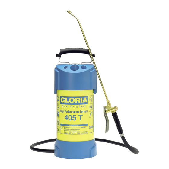
- Page 1 Geräte für Haus und Garten I n structi o ns for USE 405 T, 405 TKS, 505 T 410 T, 410 TI, 410 TRK, 410 TKS, 510 T, 510 TRK DIN EN ISO 9001 QS 9000 · VDA 6. 1...
- Page 2 5 L. Profiline 405 T / 405 TKS / 505 T...
- Page 3 5 L. Profiline 405 T / 405 TKS / 505 T...
- Page 4 10 L. Profiline 410 T / 410 TI / 410 TRK / 410 TKS / 510 T / 510 TRK 17 a...
- Page 5 10 L. Profiline 410 T / 410 TI / 410 TRK / 410 TKS / 510 T / 510 TRK...
- Page 6 410 TRK / 510 TRK -90° +90°...
-
Page 8: Table Of Contents
12 months, to ensure that continued safe Precautions operation is possible. The instructions Repairs to GLORIA house and gar- of the manufacturer are to be fol- den equipment should only be car- lowed. The inspection can be delayed... - Page 9 G Store the unit in a place out of the extinguishing agents (powder, foam, or lightwater), but not water. reach of children. G Check the functioning of the unit each G Do not leave a ready-filled unit unat- time before startup, and make a special tended at the place where it is being check of the hose connection and the used.
-
Page 10: Getting Started
Fig. 21 22 9 10 33 34 G Screw spray tube and spraying GLORIA replacement parts were not used to replace defective or worn- 23 24 35 36 lance to the quick closure valve. Im- out parts and the repair was not car-... - Page 11 Fitting the spraying lance - Compressor boost pressure or compressed air supply secu- Fig. G Screw spray tube and spraying red onto max. 6 bar. - Ensure the pump is in the locked lance to the quick closure valve. Im- position before pressurizing.
-
Page 12: Spraying
15 a 11 a reached. earthing connection (Fig. 11) is provided 16 a 17 a (see GLORIA special accessory Art. No. Spraying 726035.0000) and the unit is to be G To start the spraying process push earthed: use a standard commercially- available earthing cable. -
Page 13: Emptying And Servicing
2. Once the axle noses are in- Fig. serted, the axle must be rotated G 1. Position the handle on the pin of through 90°. the case part. 3. Now push the axle through to the Attention! The handle must stop on the opposite side. - Page 14 (welding, brazing, etc.). G To obtain optimum cleaning of the spray unit and to ensure that spray compound residues are neutralised, we recommend the use of GLORIA Special Activated Charcoal, Art. No. 263.0000. We reserve the right to make...
-
Page 15: Tips
Tips Carrying or park position 21 22 9 10 33 3 5 litre units – Fig. 21 22 33 34 9 10 Tube fastening when in park position 23 24 35 3 23 24 35 36 10 litre units – Fig. 11 a 15 a 5 litre units –... -
Page 16: Declaration Of Conformity
CE-statement of conformity for a module within the meaning of Art. 3, section 2 of the directive on pressurized equipment 97/23/EG GLORIA Haus- und Gartengeräte GmbH Därmannsbusch 7 · D-58456 Witten confirms that high performance spray units Item No. certificate- No. (Module A1) 405.…, 406…, 407…...
Need help?
Do you have a question about the Profiline 405 T and is the answer not in the manual?
Questions and answers