Table of Contents
Advertisement
Quick Links
Advertisement
Table of Contents

Related Manuals for Hammond A-162


Summary of Contents for Hammond A-162
-
Page 2: Important Safety Instructions
IMPORTANT SAFETY INSTRUCTIONS Read these instructions. Only use attachments/accessories specifi ed by the manufacturer. Keep these instructions. Use only with the cart, stand, tripod, bracket, or table specifi ed by the manufacturer, or sold Heed all warnings. with the apparatus. When cart is used: use cau- tion when moving the cart/apparatus combi- Follow all instructions. - Page 3 If the fuse cover is lost, the plug must not be used until a replacement cover is obtained. A replacement fuse cover can be obtained from your local Hammond Dealer. IF THE FITTED MOULDED PLUG IS UNSUITABLE FOR THE SOCKET OUTLET IN YOUR HOME, THEN THE FUSE SHOULD BE REMOVED AND THE PLUG CUT OFF AND DISPOSED OF SAFELY.
-
Page 4: Important - Please Read
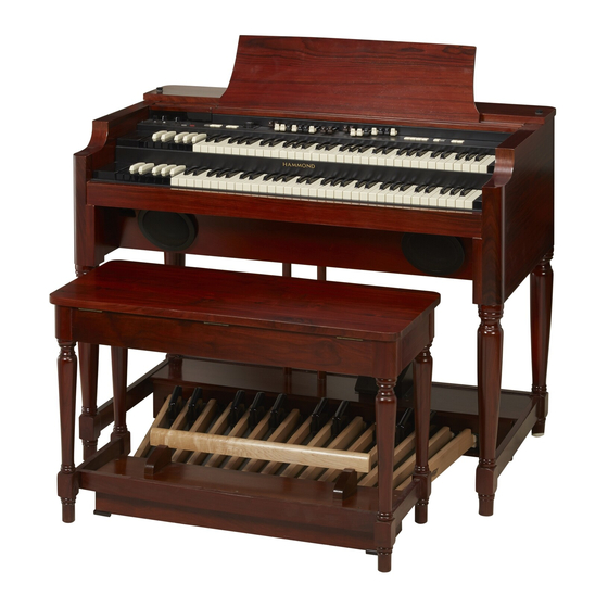
IMPORTANT - PLEASE READ Your Hammond Organ A-162 is designed to give you the true and authentic sound of Hammond Harmonic Drawbars, as well as provide you a large variety of features to allow great fl exibility in how you want to use the organ. Th is Owner’s Manual is designed to explain the operating features of your Hammond A-162 as simply and graphically as possible. -
Page 5: Battery Back Up
PRESET TRANSPOSE After the above message is displayed, the A-162 will re-initialize itself, and the factory de- fault settings will be restored (except Presets, Leslie Cabinets and Custom Tone Wheels). Th erefore, it is a good idea to periodically save your data to a CompactFlash™ card. -
Page 6: Table Of Contents
PEDAL Drawbars ..................35 Table Of Contents Drawbar Registration Patterns ..............36 Flute family (2 step pattern) ...............36 IMPORTANT SAFETY INSTRUCTIONS ..........2 Reed family (triangle pattern) ..............36 Diapason family (check mark pattern) ...........36 IMPORTANT - PLEASE READ ..............4 ... - Page 7 KEYBOARD CHANNELS .................88 Bank A “MIDI Presets” ................. 119 EXTERNAL ZONE CHANNELS..............88 Bank A “Hammond Theatre Presets” ..........119 USING AN EXTERNAL SEQUENCER ..........89 Bank B “Hammond Liturgical Presets” ..........119 Recording to the Sequencer or the Computer ........89 DEMONSTRATION SONGS ...............
- Page 8 Tune 69 Index Leakage Noise 71 Leslie 27, 42, 74 Velocity 63, 73, 92 Leslie Parameter 74 Vibrato & Chorus 27, 41, 78 Volume 92 Back-Up 22 Bank 24 Menu Mode 54 MIDI 86 Zones 92 Cabinet Number 74 CF Card 98 Name 47 Click 62 Number 24...
-
Page 9: Main Features
50W 3CH AUDIO AMPLIFIER Th e A-162 has a built-in 50 watt 3-channel (Left, Right and Center/Bass) amplifi er, en- abling you to get a full range of sound from the self-contained speaker system. -
Page 10: How To Assemble
HOW TO ASSEMBLE Components Organ Music Rack (Attached under the lid of the bench) A. C. Power Cable Pedalboard Bench Owner’s Manual... -
Page 11: Connect The Pedalboard
Connect the Pedalboard 1. Place the Pedalboard on the fl oor in front of the organ. 2. Take the Pedal Cable out of the organ and insert the plug into the connector on the Pedalboard. 3. Hold the plug with the “Retention Hook” and lock it on by turning the screw knob. -
Page 12: Names And Functions
NAMES AND FUNCTIONS Top Panel JUMP / STORE UPPER RIGHT OVERDRIVE ON Button Switches the Overdrive eff ect “ON” and “OFF.” (P. 43) POWER Switch TRANSPOSE Buttons Th is switch turns the power “ON” and “OFF.” (P. 22) Transposes the entire organ up or down by semitones. (P. 49) CAUTION Even when the POWER is turned “OFF, ”... - Page 13 VIBRATO AND CHORUS COUPLER SWELL ON Button PEDAL TO GREAT Button Switches the Vibrato and Chorus eff ects “ON” and “OFF” on Th is is for playing the PEDAL part using the GREAT manual. the SWELL Drawbar part. (P. 41) (P.
-
Page 14: Upper Left
Upper Left JUMP / STORE CONTROL PANEL Display Various information is displayed here. (P. 52) PAGE Buttons Th is is used to scroll through the various pages of controls and parameters. (P. 52) PARAM Buttons Th is is used for selecting the parameter item to edit, also to select items #1 and #2 on the basic edit pages. -
Page 15: Underside Of Manual
Underside Of Manual FOOT SWITCH 2 Jack Th is jack is for a Foot Switch (= FS-9H - optional) and the Leslie Switch (= CU-1 - optional). You can switch the speed of the Leslie eff ect, change Presets, etc. while playing. (P. 20) HEADPHONES Jack Th is is for connecting the stereo headphones. -
Page 16: Pedals
Pedals EXPRESSION Pedal Th is is for changing the total dynamics of the organ. Th e Foot Switch is attached on the top left. (P. 25) Pedalboard 25 notes. Radial fl at type, non-velocity. Owner’s Manual... -
Page 17: Hook-Up
HOOK-UP... -
Page 18: Basic Hook-Up
BASIC HOOK-UP Th is organ has a built-in speaker system, so you can start playing immediately after connecting to the power source by inserting the AC plug to the AC outlet. to AC outlet CAUTION Do not expose this organ to any ex- cessive heat sources such as direct sunlight or fl ames. -
Page 19: Using A Midi Sound Module
USING A MIDI SOUND MODULE Each Manual and the Pedalboard on this organ has an External Zone for controlling external MIDI sound modules. When Connected to the LINE IN jacks, the external MIDI sound module output is sent to the built-in speakers, stationary channel of the Leslie terminal (on a multi-channel Leslie), the LINE OUT jack and the headphone jack. -
Page 20: Using An External Foot Switch
In that case, connect an unlatch-type foot switch to the “FOOT SWITCH” jack on the underside of the key bed. Th e Hammond FS-9H (optional) is recommended. Th e “FOOT SWITCH” jack is tip-ring-sleeve. So you may connect a twin- pedal-type foot switch with a stereo plug to this jack. -
Page 21: Power On And Play
POWER ON AND PLAY... -
Page 22: Power On
Also, if an external Leslie Speaker is connected to the organ, it will automatically switch “ON” when the organ is turned “ON.” The circuit protection device creates a delay of a few seconds before the A-162 is ready to play. -
Page 23: Listen To The Demonstration Performance
LISTEN TO THE DEMONSTRATION PERFORMANCE Touch and hold the [PEDAL TO GREAT] and [GREAT TO PEDAL] buttons for 2 seconds. Th e Display will be as shown in step 2. NOTE: You can locate this mode another way. From either of the PLAY screens, touch the [MENU] button to display the MENU, touch the [PAGE ] button fi ve times to select Menu F, then touch [1] DEMO. -
Page 24: Using The Combination Presets
NOTE: On the B-3/C-3/A-100, only Drawbar settings could be changed with the Preset Keys, which also is the default set- ting for this organ. However, the A-162 can memorize other parameters in addition to the Drawbar settings. See the “PRE- SET”... -
Page 25: Using The Controllers
USING THE CONTROLLERS Using the performance controllers will add expression to your playing. On this page you will learn how to use these controllers. Th e controllers exclusive to the Hammond are covered on the next page. Expression Pedal ... -
Page 26: Try Making Your Own Sound
TRY MAKING YOUR OWN SOUND You will be able to produce your own sound by using the exclusive features of your Ham- mond Organ, such as Drawbars, Percussion, Vibrato & Chorus, Leslie eff ects, and Reverb. Let’s go through the fi rst steps: Select the SWELL “B”... -
Page 27: Add Effects
Add effects Vibrato and Chorus “Vibrato and Chorus” slightly changes the Drawbar pitch at a certain ratio and adds warmth to the sound. [SWELL] Button [GREAT] Button Switches the Vibrato eff ect “ON” and “OFF.” When the button is “ON”, the LED will light. -
Page 28: Pedal Sustain
Pedal Sustain Th e PEDAL Drawbar sound can be set to smoothly decay after the pedal is released. Th is is called “PEDAL SUSTAIN”. To use this “Pedal Sustain” function, switch the [PEDAL SUSTAIN] button “ON.” Th e LED will light. If you release your foot off the Pedal (or your fi nger from the GREAT manual, if you are using the Pedal to Great, as explained later in this manual), the PEDAL Drawbar sound smoothly decays. -
Page 29: Storing Registrations To Presets
Storing registrations to Presets Ex. Memorize to “F - D” for GREAT part Press and Hold While touching and holding the [BANK] button, press the “F” Preset Key on the SWELL manual. Light Th e LED on the Preset Key indicates BANK while the [BANK] button is touched. - Page 30 Owner’s Manual...
-
Page 31: Setting Up
SETTING UP... -
Page 32: Sound Engine Structure
SOUND ENGINE STRUCTURE Pedal Great&Swell Virtual Virtual Tonewheel Tonewheel Swell(Upper) Great(Lower) Pedalboard Manual Manual Percussion Pedal Great Swell Drawbars Drawbars Drawbars Vibrato & Chorus switchable Overdrive Digital Reverb TC & Equalizer Leslie Expression switchable Speakers Line Out Leslie 11Pin Owner’s Manual... - Page 33 Chorus function of the B-3/C-3/A-100. NOTE: On the classic B-3/C-3/A-100 the chorus/vibrato eff ect was obtained by an electro-me- chanical “scanner”. The A-162 uses a digital model of that scanner that gives an accurate reproduction of the original. OVERDRIVE Overdrive adds the fuzzy, raspy, “dirty”...
-
Page 34: Harmonic Drawbars
HARMONIC DRAWBARS™ Th e 9 Drawbars for each keyboard (plus 2 for the PEDAL) of the A-162 organ are used to make the basic sounds. If you pull out a Drawbar, you will see a series of numbers appear from 1 through 8. Th is indicates the volume or loudness of the tone called on by that Drawbar. -
Page 35: Manual Drawbars
Manual Drawbars White Drawbars In each Drawbar set, the fi rst white Drawbar (8´) plays in the basic octave of the organ. Th e other Drawbar pitches are fi g- ured in reference to this pitch, up or down. Th e other white Drawbars get higher by the octave to the right. -
Page 36: Drawbar Registration Patterns
Drawbar Registration Patterns Th e Drawbar Registration is matched by numbers. It is easy to remember the typical combinations of the 9 Drawbars by their shapes or patterns. Th e Drawbar Registrations are grouped into the following 4 patterns: Flute family (2 step pattern) ... -
Page 37: Modern Drawbar Registrations
Modern Drawbar Registrations Th e Drawbar registrations shown on the previous page are intended to simulate pipe organ registrations since the original intent of the Hammond Organ was to provide a lower-cost alternative to a church pipe organ. As the Hammond Organ gradually achieved acceptance in other musical fi elds, such as Pop, Jazz, Rock and Gospel, unique registrations became commonplace. -
Page 38: Match The Registration To Drawbars
Match the Registration to Drawbars When you recall a Preset, the Drawbar Registration is not changed physically but is replaced with the one stored in the Preset. If you move any Drawbar at this stage, only that Drawbar will change. To match the Registration to the Drawbars while a Preset is active, touch and hold the Preset Key for approximately 1 second. -
Page 39: Controlling The Registration While Playing A Preset
Controlling the Registration while playing a Preset Th e A-162 allows you to select whether you want to have active Drawbars on all the Presets or on the “B” Preset only as on a B-3/C-3/A-100. You can make this selection in the Control Mode portion of the Drawbars - Control Mode. -
Page 40: Percussion
PERCUSSION Th e Touch-Response Percussion adds a clear-cut “attack” to the organ sound. It is a Hammond exclusive. Percussion is usually combined with the Drawbar sound. [SECOND] button Th e second harmonic, or 4´ Drawbar decay, is added to the SWELL manual. -
Page 41: Vibrato And Chorus
VIBRATO AND CHORUS Th e VIBRATO gives warmth and variance to the organ’s tone by slightly but rapidly raising and lowering the pitch. CHORUS creates the eff ect of vibrato and non-vibra- to tones played simultaneously, giving a “shimmering” sound. [SWELL] button Th is switches the Vibrato and Chorus eff ects for the SWELL Drawbars “ON”... -
Page 42: Leslie
These are called “Stationary channels” because they do not use rotors to animate the sound. The built-in digital Leslie eff ect on the A-162 will replicate the eff ect of a single-channel Leslie Speaker or the Rotary channel of a multi-channel Leslie Speaker. -
Page 43: Overdrive
OVERDRIVE Th e Overdrive gives distortion to the sound by increasing the pre-amplifi er input gain. [OVERDRIVE ON] button To hear the Overdrive eff ect, touch this button and the LED will light. [OVERDRIVE] knob Adjusts the amount of the Overdrive eff ect. Rotating the knob clockwise increases the depth of the eff ect. -
Page 44: Tone
TONE You can adjust the Tone control instantly. Th e Tone knob controls the built-in 3-band Equalizer and traditional Tone control. JUMP / STORE To adjust the Tone, open the lid of the control panel. Tone Control [TONE TYPE] button Gain Select the parameter which will be controlled by the [TONE] knob. -
Page 45: Reverb, Pedal Sustain, Coupler
REVERB, PEDAL SUSTAIN, COUPLER Many Organists prefer their PEDAL (Bass) voices to smoothly decay in the style of a String Bass. Depressing the [PEDAL SUSTAIN] tab turns this function “ON.” When this function is active, the LED will light. Some Organists prefer to play the Bass parts on the GREAT manual instead of the Pedals. -
Page 46: Presets
PRESETS Th e settings you have made can be recorded into the Presets. Bank and Key Bank B Th e Preset chart to the left shows the [BANK] and the [KEY], Bank ~ Swell Preset Key information. Bank D Swell Preset Key Bank C Th e SWELL and GREAT Presets are independent;... -
Page 47: Name The Current Setting
Name the current setting Go to the MENU. Go to the PRESET function mode. JUMP / STORE JUMP / STORE Touch the [MENU] button. Touch the [2] PRESET button and go to the PRESET func- tion mode. Th e MENU mode will be displayed. Th e fi rst page is for the SWELL name. -
Page 48: Recording Your Own Presets
NOTE: The Preset Data is remembered when the power to the organ is switched “OFF.” NOTE: On the A-162, all the Preset Keys from “C” through “A ” can memorize registrations. However, it is not recommended that you record a Preset into the “C” key, since that key is normally used to Cancel Drawbar settings as on the vintage B-3/C-3/A-100 organs. -
Page 49: Transpose
For example, if you set Transpose at [+5], the note “F” sounds when you play the “C” key. (By playing in the key of C the A-162 sounds in the key of F.) [TRANSPOSE] buttons ... - Page 50 Owner’s Manual...
-
Page 51: Using The Control Panel
USING THE CONTROL PANEL... -
Page 52: Using The Control Panel
USING THE CONTROL PANEL Th e CONTROL PANEL allows the deep editing of the adjustable parameters of the A-162, and shows the status of the organ at any given time. It is the “Nerve Center” of the Organ. If you raise the lid on the left side just above the 3 Rotary Knobs, you will see the LCD display. -
Page 53: Play Mode
PLAY MODE Th e PLAY mode is the basic display for normal playing. Th e necessary information for nor- mal play will be displayed. Th ere are two types of PLAY mode screens to display the Drawbar Registration. One is by showing the length of the bars in graphic display and the other by numbers. To Locate this mode: 1. -
Page 54: Menu Mode
MENU MODE Th e MENU mode displays the path for each function. To locate this mode: Touch the [MENU/EXIT] button. Th ere are several pages which contains various FUNCTION displays. Move from page to page to fi nd the item you wish to edit and touch the numbered button to view the desired display. -
Page 55: Menus And Their Contents
You can adjust the settings for the Reverb eff ect. (P. 81) EQUALIZ You can adjust the settings for the Equalizer. (P. 80) TUNE You can adjust the overall tuning of the A-162. (P. 69) Page D ZONES You can adjust the internal and external zones. (P. 92) MIDI You can adjust the basic MIDI settings. -
Page 56: Function Mode
FUNCTION MODE Th e FUNCTION mode is for making each setting and adjustment. Th ere are many displays, but the basic operation is the same. How to read the display This shows there are PAGEs above (or below). PARAMETER This shows there are PAGEs on the right (or on the left). -
Page 57: Short Cut To The Function Mode
SHORT CUT TO THE FUNCTION MODE Each button on the panel has a “SHORT-CUT” capability, so that you can easily move to each FUNCTION mode. By holding down the button, you move directly to the desired mode display. You can save time to search the page for the parameters you want to change. -
Page 58: Example Of Operation
Example of operation: Adjusting the DECAY TIME of the Percussion [FAST] Go to the MENU mode. Touch the [MENU] button. Th e MENU mode is displayed. JUMP / STORE Select the PAGE. Search for the PERCUSS page, using the [PAGE] button. “PERCUSS”... - Page 59 Move the CURSOR to the Parameter you want to change. DECAY TIME is on the “DECAY” page. Move to that page using the [PAGE] button. “FAST” is on the right side of the display. Move the CUR- SOR (fl ashing value) to “FAST” using the [PARAM] button. JUMP / STORE Change the value.
-
Page 60: Lock The Display In Play Mode
LOCK THE DISPLAY IN PLAY MODE Th is advanced feature allows you to put the organ into a special playing mode whereby the Control Panel is rendered inoperative. Touching any of the MENU Touch Buttons will have no eff ect. Th is is useful when you want to place the organ in public halls, churches or audi- toriums. -
Page 61: Setting The Parameters
SETTING THE PARAMETERS... -
Page 62: Drawbar
This sound includes more leakage noise and fl utter. Mellow: Transparent sine wave. KEY-CLICK Brite: The analog-oscillating sound of the vintage Hammond X-5. The “Key Click” is the noise heard every time the Saw: Sawtooth waveform (Non-Hammond “Combo Organ” Style). key is touched or released on the B-3/C-3/A-100,... -
Page 63: Pedal Drawbars
Th is allows you to select the tone wheel set (waveform) of the PEDAL Drawbars. Normal: The traditional B-3/C-3/A-100 tone wheel sound. Muted: Analog-oscillating sound represented by the vintage Hammond X-5. Synth1: Sawtooth waveform with sweep fi lter. Synth2: Dull square waveform. -
Page 64: Preset
PRESET In this mode, you can name your Presets and determine how to recall them. To locate this mode: 1. From either of the PLAY screens, touch the [MENU/EXIT] button. Menu A will display. 2. Touch the [2] PRESET button. ... -
Page 65: Preset Bank
PRESET LOAD - ANIMATION (B) Th is allows you to determine whether or not to recall the Parameters relating to the Vi- brato and Chorus, and Leslie eff ects by a SWELL Preset Key, and Vibrato and Chorus for GREAT manual by a GREAT Preset Key. PRESET LOAD - EQUALIZER / REVERB (B) Th is allows you to determine whether or not to recall the Parameters relating to the Equalizer and Reverb by a SWELL Preset Key. -
Page 66: Control
CONTROL In this mode, you can adjust the settings of each controller. To locate this mode: 1. From either of the PLAY screens, touch the [MENU/EXIT] but- You may change the functions of several of the playing controls of ton. Menu A will display. the organ. -
Page 67: Expression
FOOT SWITCH 2 - RING MODE (G) EXPRESSION LIMIT Th is is for setting the function on the RING contact, if you use the Foot Switch with a One of the human ear’s characteristics is that stereo adapter. when the volume falls, the sound of high or low frequencies becomes diffi cult to hear. -
Page 68: Display
(omitted) DISPLAY DISPLAY - SHORT CUT (G) Sets the time limit to the short cut function. Th e range 0 to 2 seconds and NO short cut. Th e short cut function does not work when the value is “NO”. DISPLAY - TIME OUT (G) Sets the time limit to return to the previous screen from the one displayed by using the short cut operation. -
Page 69: Tune
TUNE Th is mode allows you to adjust the overall tuning of the A-162. To locate this mode: 1. From either of the PLAY screens, touch the [MENU/EXIT] button. Menu A will display. 2. Touch the [PAGE ] button three times. Menu D will display. -
Page 70: Cust. Tw (Custom Tone Wheels)
As a sample for customization, the typical settings are programmed had 96. Th us the CUST.TW feature can be used to replicate any at the factory. console Hammond Organ which used tone wheels to produce the sounds. To locate this mode: 1. - Page 71 This “hash” noise, another Hammond anomaly originally considered to be a defect, Th e setting range is 0 - 127. grew to be an integral part of the Hammond NOTE: If you increase the value too high above the original tone sound.
-
Page 72: Store The Custom Virtual Tone Wheels
Store the CUSTOM virtual tone wheels Th e tone wheel Parameters (= 3 - 8 of the previous paragraph) can be stored as a Custom Tone Wheel. In this way you can recall your parameter settings during performance. Enter the Custom Name if desired. (P. 70 #3) JUMP / STORE Select the Custom Number to be recorded by the [PAGE] but- ton. -
Page 73: Percuss (Percussion)
OFF: This replicates the “legato non-retriggering” Percussion function On the B-3/C-3/A-100, the Drawbar Volume on the X-66, Concorde and later model Hammond Organs. Each was slightly reduced when the Percussion was key will sound when played regardless of whether other keys are engaged. -
Page 74: Leslie
Th is sets the type of the virtual speaker. RotSmall: A small (33˝ tall) cabinet such the model 142. RotLarge: A standard-size (41˝ tall) cabinet such as the model 122. Station: A stationary speaker such as the Hammond PR-40. Owner’s Manual... - Page 75 SLOW SPEED - HORN (L) Mode: SLOW FAST SLOW FAST BRAKE SLOW SPEED - BASS (L) Th is sets the speed of the Rotor in Slow mode. Th e setting range is 0, 24 - 318 rpm. It does not rotate at 0. FAST SPEED - HORN (L) FAST SPEED - BASS (L) Rotor...
-
Page 76: External Leslie Speaker
EXTERNAL LESLIE SPEAKER LESLIE CHANNEL (S) Th e Channel is set for the Leslie Speaker connected to the 11-pin terminal. 1ch: Use this setting when connecting to a 122XB, 971/981/3300(not expanded), 147, 771, or other single-channel Leslie cabinet. The Drawbar and Percussion sounds will be heard through the single Rotary channel. -
Page 77: Store The Cabinets
Store the Cabinets Th e Leslie parameters (#2 - 19 of the previous paragraph) can be stored with the Cabinet numbers, and you can choose and use them in each Preset. Enter the name for the Cabinet. (P. 74 #2) JUMP / STORE Select the Cabinet Number to record by the [PAGE] button. -
Page 78: Od/Vib (Overdrive / Vibrato)
OD/ VIB (OverDrive / VIBrato) In this mode, you can change the settings for Overdrive, Vibrato and Chorus. To locate this mode: 1. From either of the PLAY screens, touch the [MENU/EXIT] button. Menu A will display. 2. Touch the [PAGE ] button once. Menu B will display. 3. -
Page 79: Vibrato And Chorus Of Hammond Organs
On this model, the chorus and vibrato eff ects are replicated in the original fashion digi- tally by our proprietary DSP, without using moving parts. Hammond Classic “Scanner Vibrato” (Physically Modelled on the A-162) -
Page 80: Equaliz (Equalizer)
-3dB Th e setting range is -9 to +9, and it becomes neutral when set at “0”. NOTE: On the A-162, this can also be used to boost the treble as well as cut it. -9dB “-1” corresponds to the maximum of the B-3/C-3/A-100 tone control, “-5”, the -15dB middle, “-9”... -
Page 81: Reverb
REVERB In this mode, you can adjust the setting for the Reverb eff ect. To locate this mode: 1. From either of the PLAY screens, touch [MENU/EXIT] button. Menu A will display. 2. Touch the [PAGE ] button twice. Menu C will display. 3. -
Page 82: Default
DEFAULT In this mode, you can restore the organ to its factory default settings. You can choose to reset the entire system or only selected portions of it. To locate this mode: 1. From either of the PLAY screens, touch the [MENU/EXIT] button. Menu A will display. 2. -
Page 83: System
SYSTEM In this mode, you can set the System Parameters of this organ and the display information. To locate this mode: 1. From either of the PLAY screens, touch the [MENU/EXIT] button. Menu A will display. 2. Touch the [PAGE ] button four times. Menu E will display. 3. - Page 84 Owner’s Manual...
-
Page 85: Midi
MIDI... -
Page 86: About Midi
ABOUT MIDI What is “MIDI” ? MIDI is an abbreviation of Musical Instrument Digital Interface. MIDI is the musical instrument industry standard for exchanging performance infor- mation between electronic musical instruments and a sequencer, eff ects, lighting and sound reinforcement gear, etc. Th e MIDI standard allows instruments made by diff erent manufacturers to eff ectively communicate with each other. - Page 87 MIDI CHANNEL A “MIDI Channel” is the avenue along which MIDI information is sent and received. It is similar in principle to television channels. Up to 16 MIDI Channels can be sent or received. In order for MIDI communication to take place, the transmitting and receiving instru- ments must be set to the same channel - for instance, if one instrument is sending out MIDI data on MIDI Channel 1, the receiving instrument must also be set to MIDI Channel 1.
-
Page 88: Midi Structure
MIDI STRUCTURE Th is organ has a “Keyboard Channel” for transmitting (sending/receiving) the play- ing information of each manual as well as an “External Zone Channel” for controlling an external MIDI equipment. Keymap Overview Virtual Tonewheel Sound Engine Octave Switch Swell ExZone Swell Drawbar On / Off Switch... -
Page 89: Using An External Sequencer
USING AN EXTERNAL SEQUENCER Th is is the method to record and play back your performance by connecting a Se- quencer or Computer to your organ. Computer MIDI Interface MIDI IN MIDI OUT MIDI Cables Recording to the Sequencer or the Computer 1. -
Page 90: Using A Midi Compatible Leslie Speaker
USING A MIDI COMPATIBLE LESLIE SPEAKER If you connect this organ and the Leslie speaker through MIDI, you can send the Leslie parameters such as the rotor speed and the rise time to the Leslie speaker and can make fi ner adjustment than connecting only with the Leslie cable. MIDI compatible Leslie Speaker MIDI cable... -
Page 91: Using A Midi Sound Module
USING A MIDI SOUND MODULE You can control external MIDI equipment with a zone for each of the SWELL and GREAT manuals and Pedalboard. LESLIE 11PIN MIDI MICROPHONE LINE IN LINE OUT MIN. MAX. VOLUME L / MONO (KEYBOARD) (MULTI) LINE OUT MIDI IN MIDI Sound Module... -
Page 92: Zones
ZONES Th e EXTERNAL ZONES allow you to use the SWELL and To locate this mode: GREAT manuals and the Pedals to control external MIDI equip- 1. From either of the PLAY screens, touch the [MENU/EXIT] but- ment independently of the Drawbars. ton. -
Page 93: Panic Function And Parameter Reload
NOTE: The velocity of the PEDAL External Zone (PXZ) is fi xed at OFF since the Pedalboard of this organ has no velocity sensing function. EXPRESSION - MINIMUM EXPRESSION - MAXIMUM Th ese allow you to widen or narrow the volume range of the Expression Pedal for the External Zones. -
Page 94: Midi
MIDI Th is adjusts the basic settings of the MIDI. To locate this mode: 1. From either of the PLAY screens, touch the [MENU/EXIT] button. Menu A will display. 2. Touch the [PAGE p] button four times. Menu E will display. 3. -
Page 95: Channels
RECEIVE DUMP Th is is for determining whether or not to receive the Memory Dump. You can use the MEMORY DUMP feature to transmit and receive the current settings via System Exclusive data, but you must set this switch to “OFF” if you do not want the settings of this organ to be changed. - Page 96 Owner’s Manual...
-
Page 97: Save The Setup
SAVE THE SETUP... -
Page 98: Save The Setup
You can then save the Setup to a CompactFlash™ Card (hereinafter “CF card”). Eject Button About CF Card RECOMMENDED CF CARDS Th e manufacturer recommends you use genuine Hammond CF Cards (#65971- 02128). Please consult http://www.hammondorganco.com before you try to use other cards in this organ. -
Page 99: Initialize The Cf Card
INITIALIZE THE CF CARD Th e CF Card must be “INITIALIZED” before you use it. Perform the following, step by step, to do the initialize operation. This operation erases all data in the CF Card. Insert the CF Card into the slot. JUMP / STORE Touch the [3] CF FORM. -
Page 100: Setup Mode
SETUP MODE Th e SETUP mode allows you to Save or Load SETUPs to/from a CF card. In this mode, you can do all the operations except the initialization of the CF card. To locate this mode: 1. From either of the PLAY screens, touch the [MENU/EXIT] button. Menu A will display. 2. -
Page 101: Change The Setup Name
Change the SETUP Name JUMP / STORE JUMP / STORE Select the Setup fi le you want to rename. Use the [PARAM] button to scroll to the end of the name. [ENT] will be displayed. JUMP / STORE JUMP / STORE Touch the [3] NAM button. -
Page 102: Load The Setup
Load the Setup How To Delete the Setup When you load a Setup from a CF card, the current settings are overwritten with the settings from the new Setup. Therefore, if the current Setup contains Make sure the CF Card is correctly inserted. information you don’t want to lose, it is highly recom- mended that you back up the existing Setup to a CF card so that you have a permanent record of it. -
Page 103: Frequently Asked Questions
FREQUENTLY ASKED QUESTIONS... -
Page 104: Troubleshooting
TROUBLESHOOTING Malfunction of the buttons, the keys, etc. Turn the POWER Switch “OFF” once, then turn it back “ON.” If this procedure is not success- ful, turn the POWER Switch “OFF.” While touching the [RECORD] button, turn the POWER Switch “ON”... -
Page 105: Instrument Care
INSTRUMENT CARE AC Power Be sure to turn the instrument “OFF” after use, and do not turn the unit “ON” and “OFF” in quick succession, as this places an undue load on the electronic components. Cabinet And Bench As with any piece of furniture, direct sunlight can damage the fi nish of your instrument. - Page 106 Owner’s Manual...
-
Page 107: Appendix
APPENDIX... -
Page 108: Custom Tone Wheel Presets
CUSTOM TONE WHEEL PRESETS BType1, BType2 Real B-3 Th is preset faithfully simulates the classic model, B-3. It contains low motor hum and some leakage noise. 80’s Clean Th is preset simulates the B-3 sounds in the 80’s. It contains reduced leakage noise. Noisy Th is preset is for passing all sounds picked up by the magnets on each tone wheel. -
Page 109: Midi Templates
MIDI TEMPLATES Template Seq. Local Seq. No Local Leslie Messages Local Control NRPN Drawbar Registration Program Change Leslie Control Code Organ Organ Leslie 21 Transmit Channel SWELL manual GREAT manual Pedalboard Leslie Comments Use this template for connect- Use this template for connect- Use this template for connect- ing the organ to an external ing the organ to an external... -
Page 110: Midi Information
MIDI INFORMATION MIDI Implementation Program Change Channel Voice Message Status 2nd Byte Note Off n=MIDI Channel Number: 0H - FH (Ch. 1 - 16) Status 2nd Byte 3rd Byte pp=Program Number: 00H - 7FH (prog. 1 - prog. 128) vvH, or Pitch Bend Change n=MIDI Channel Number:... -
Page 111: Drawbar Data List
Drawbar Data List Control Number Part 16´ 5 1⁄3´ 8´ 4´ 2 2⁄3´ 2´ 1 3⁄5´ 1 1⁄3´ 1´ 0CH(12) 0DH(13) 0EH(14) 0FH(15) 10H(16) 11H(17) 12H(18) 13H(19) 14H(20) SWELL 15H(21) 16H(22) 17H(23) 18H(24) 19H(25) 1AH(26) 1BH(27) 1CH(28) 1DH(29) GREAT 21H(33) 23H(35) PEDAL Level... -
Page 112: System Exclusive Message
System Exclusive Message NRPN Switch Memory Dump 1. Each Packet System Exclusive System Exclusive SUZUKI ID SUZUKI ID Device ID Device ID (refer to P. 94 #7) Model ID MSB Model ID MSB Model ID LSB Model ID LSB Command: NRPN Sw. -
Page 113: Global Parameters
Global Parameters Category Parameter NRPN SysEx Address SysEx Data Default Description MSB to LSB Length (62) (63) Transpose 3A - 40 - 46 Tune (-6 - 0 - 6) Master Tune 032E - 0338 - 0342 0338 (430 - 440 - 450) Expression Source 00 - 02... -
Page 114: Preset Parameters
Preset Parameters Category Parameter NRPN SysEx Address SysEx Data Preset Load MSB to LSB Length (62) (63) 10 Characters 7 bit ASCII always SWELL Name GREAT Name 10 Characters 7 bit ASCII always Internal Zone Pedal To Swell 00, 01 (Off /On) IN-S SWELL P to S Range Hi... - Page 115 Category Parameter NRPN SysEx Address SysEx Data Preset Load MSB to LSB Length (62) (63) SWELL Draw- 16´ 00 - 08 (0 - 8) bars 5 1/3´ 00 - 08 (0 - 8) 8´ 00 - 08 (0 - 8) 4´...
-
Page 116: Leslie Parameters
Category Parameter NRPN SysEx Address SysEx Data Preset Load MSB to LSB Length (62) (63) Equalizer, EQ Bass Gain 00 - 09 - 12 (-9 - 0 - +9) EQRV Reverb EQ Mid Gain 00 - 09 - 12 (-9 - 0 - +9) EQ Treble Gain 00 - 09 - 12 (-9 - 0 - +9) EQ Mid Frequency... -
Page 117: Midi Implementation Chart
MIDI IMPLEMENTATION CHART Date: 16-Apr-2013 Chapel Console Organ MIDI Implementation Chart Version: 1.0 Model: A-162 Function Transmitted Recognized Remarks *1: SWELL = 1, GREAT Basic Default Changed 1 - 16 1 - 16 = 2, PEDAL = 3 Channel Default... -
Page 118: Factory Presets
FACTORY PRESETS Bank C “Jazz 1” C D F G A Cancel Jimmy Lo & Hi 1 Warmth Groove Funky Purple Funky 2 Full Tibias Full Organ Full Church SWELL GREAT Cancel Jimmy Lo & Hi 1 Warmth Groove Funky... -
Page 119: Bank G "User Presets
Pizzicato Str Chimes Brite Piano Dist Guitar New Age Pad Choir&Orgn GREAT Th is bank desired use with GM Level 1 sound module. Bank A “Hammond Theatre Presets” C D F G A Cancel... -
Page 120: Specifications
SPECIFICATIONS Sound Generator Controllers Drawbars Volumes 2 - VASE III as Digital tone wheels, 61 - note polyphony Master Volume, External Leslie Volume Pedal Keyboards Expression Pedal w/1 - Foot Switch SWELL: 73 (C1 to C6 61-key + 12 Preset Keys) Storage GREAT: 73 (C1 to C6 61-key + 12 Preset Keys) PEDAL: 25-note radiating, detachable... -
Page 121: Service
Although every attempt has been made to insure the accuracy of the descriptive contents of this Manual, total accuracy cannot be guaranteed. Should the owner require further assistance, inquiries should fi rst be made to your Authorized Hammond Dealer. If you still need further assistance, contact Hammond at the following addresses:... - Page 122 Printed in Japan 00457-40191 V1.01-140609 HAMMOND SUZUKI, LTD., Hamamatsu, Japan...
Need help?
Do you have a question about the A-162 and is the answer not in the manual?
Questions and answers