
Related Manuals for Hammond A


Summary of Contents for Hammond A
- Page 1 Organ Manual for the SERVICE ENGINEER Models: A-100, AB, BC, BCV, BV, B2, B3, C, CV, C2, C2-G, C3, D, DV, D-100, E, G, GV, RT, RT2, RT3 This manual is intended for FREE distribution...
- Page 2 Parts List itself due to their obsolescence. The diagrams have been scanned at a 600dpi resolution from the oldest sources that could be found. These older sources were typically fold out diagrams 17"x11" in size.
- Page 3 THE HAMMOND ORGAN MANUAL FOR THE SERVICE ENGINEER HAMMOND ORGAN COMPANY North Western Avenue - Chicago Diversey Ave - Chicago North 25 Avenue - Melrose Park Copenhagen Court - Franklin Park Illinois...
- Page 4 FOREWORD The Hammond Organ is a product of a company which enjoys a world-wide reputation as a manufacturer of precision electrical devices. The manufacturing facilities devoted to the production of the organ are the finest in existence for this type of work.
-
Page 5: Safety Notice
Connect the network (as shown below) In series with all exposed metal parts and a known earth ground such as a water pipe or conduit. Use an AC VOM of 5,000 ohms per volt or higher sensitivity to measure the voltage drop across the network. -
Page 6: The Hammond Organ
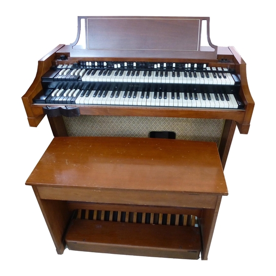
THE HAMMOND ORGAN – 1 – INTRODUCTORY SECTION HAMMOND ORGAN COMPANY North Western Avenue - Chicago Diversey Ave - Chicago North 25 Avenue - Melrose Park Copenhagen Court - Franklin Park Illinois... - Page 7 SPECIFICATIONS MODEL A - AB IN PRODUCTION: June 1935 to October 1938. SELLING PRICE: $1,193.00. With Model A-20 Tone Cabinet $1,250.00. D I M E N S I O N S : C l o s e d : 48-1/2" wide, 37-5/8" high, 24" deep.
- Page 8 38-3/8" high. Open, with pedal keyboard and bench: 48-3/8" wide, 49-1/2" deep, 46" high. MODEL AB: Same as Model A but enclosed in larger woodwork. One tone generator, one adjustable tremulant affecting both manuals and pedals equally. Also see Model A for price and pro- duction dates.
- Page 9 SPECIFICATIONS HOME MODELS BC, BV, BCV, B-2, AND B-3 (Continued) MODEL B-3:Same as Model B-2 but with Hammond Percussion feature. IN PRODUCTION: January 1955 to SELLING PRICE: $2,745.00 - Walnut. $2,835.00 - Cherry. M A N U A L S : Swell and Great, 61 playing keys each.
- Page 10 "normal" or "soft" overall volume. IN PRODUCTION: December 1949 to December 1954. SELLING PRICE: $2,178.00 - Walnut. MODEL C-3:Same as Model C-2 but with Hammond Percussion feature. IN PRODUCTION: January 1955 to SELLING PRICE: $2,545.00 - Walnut. $2,630.00 - Oak.
- Page 11 M A N U A L S : Swell and Great, 61 playing keys "ch. P E D A L K E Y B O A R D : 25-note, radiating, detachable. T O N A L 9 preset keys and 2 sets of 9 adjustable harmonic drawbars C O N T R O L S : for each manual;...
- Page 12 32-note, concave, radiating, detachable, built to AGO K E Y B O A R D : s p e c i f i c a t i o n s . T O N A L 9 preset buttons and 2 sets of 9 adjustable harmonic draw- C O N T R O L S : bars for each manual;...
- Page 13 Produced from June 1941 to November 1944. MODEL C-2G, C-3G CONSOLES AND HR-40G These consoles are identical in appearance to the C-2 and C-3 except that a monitor speaker is located on the lower left hand side. The preamplifier in the C-2G is designed to operate the monitor speaker. In the C-3G the preamplifier is the same as in the C-3.
- Page 14 IN PRODUCTION: November 1949 to January 1955. SELLING PRICE: $2,970.00 - Walnut. C O N C E R T MODEL RT-3: Same as Model RT-2 but with Hammond Percussion feature. IN PRODUCTION: January 1955 to SELLING PRICE: $3,450.00 - Walnut.$3,555.00 - Oak.
- Page 15 32-note, concave, radiating, detachable, built to AGO K E Y B O A R D : s p e c i f i c a t i o n s . PEDAL SOLOHas pedal solo system with separate volume control, S Y S T E M : providing following solo effects;...
- Page 16 MODEL A-20 TONE CABINET S P E C I F I C A T I O N S IN PRODUCTION: October 1935 to July 1939. SELLING PRICE: $ 1 6 5 . 0 0 . D I M E N S I O N S : 27"...
- Page 17 MODEL A-40 TONE CABINET S P E C I F I C A T I O N S IN PRODUCTION: October 1935 to October 1947. SELLING PRICE: $225.00. D I M E N S I O N S : 26-1/2" wide, 28" high, 19" deep.
- Page 18 MODEL B-40 TONE CABINET S P E C I F I C A T I O N S IN PRODUCTION: November 1936 to December 1947. SELLING PRICE: $ 2 4 7 . 0 0 . D I M E N S I O N S : 36"...
- Page 19 MODEL C-20, CX-20, AND CXR-20 TONE CABINET S P E C I F I C A T I O N S MODEL C-20: IN PRODUCTION: October, 1937 to March, 1942. SELLING PRICE: $ 2 7 0 . 0 0 MODEL CR-20: Equipped with Reverberation Unit.
- Page 20 D I M E N S I O N S : 29" wide, 53" high, 18-1j4" deep. F I N I S H : Matched American butt walnut and antique brass hardware. W E I G H T : 153 lbs. O U T P U T : 20 watts, 1 amplifier, 2 - 12"...
- Page 21 MODEL C-40 TONE CABINET S P E C I F I C A T I O N S IN PRODUCTION: June 1936 to December 1937. SELLING PRICE: $330.00. D I M E N S I O N S : 38" wide, 71" high, 27-1/2" deep.
- Page 22 . IN PRODUCTION: October 1937 to March 1952. SELLING PRICE: $181.00.
- Page 23 MODEL ER-20 TONE CABINET S P E C I F I C A T I O N S IN PRODUCTION: March 1947 to December 1950. SELLING PRICE: $462.00. D I M E N S I O N S : 31" wide, 38-3/4" high, 18" deep.
- Page 24 Approximately 300 watts. The F-40 replaces the B-40 tone cabinet. Dimensions of the woodwork have been altered so that a reverberation unit may be accommodated. With the addition of the reverberation unit it is designated as FR-40. T C - 9...
- Page 25 MODEL H-40, HR-40, K-40, AND KR-40 TONE CABINET MODEL H-40 AND HR-40: IN PRODUCTION: October 1948 to February 1960. SELLING PRICE: H-40 - $517.00 - Walnut. HR-40 - $585.00 - Walnut. HR-40 - $605.00 - Oak. D I M E N S I O N S : 33-1/8"...
- Page 26 MODEL H-40, HR-40, K-40, AND KR-40 TONE CABINET (Continued) The K series tone cabinets are electrically and tonally similar to the H series but are constructed in a utilitarian cabinet. Usually used in con- cealed installations. The two treble speakers usually mounted on top can be placed on the front baffle for use in chambers where vertical radiation would be restricted.
- Page 27 MODEL JR-20 TONE CABINET S P E C I F I C A T I O N S IN PRODUCTION: March 1951 to February 1959, SELLING PRICE: $452.00 - Walnut. $472.00 - Oak. D I M E N S I O N S : 29-3/4"...
- Page 28 MODEL PR-20 FRONT MODEL PR-20 REAR S P E C I F I C A T I O N S IN PRODUCTION: February 1959 to July 1963. SELLING PRICE: W a l n u t $ 4 8 5 . 0 0 O a k $ 5 0 5 .
- Page 29 O U T P U T : 55 watts E.I.A. Equipped with a two channel amplifier, two 15" speakers and two 12" speak- ers serving the bass and treble channels respectively. This tone cabinet in conjunction with a Hammond tone cabinet with reverberation can add the additional power required for larger installation at a minimum cost.
- Page 30 MODEL PR-40 MODEL QR-40 S P E C I F I C A T I O N S MODEL PR-40: IN PRODUCTION: February 1959 SELLING PRICE: $615.00 - Walnut $645.00 - Oak $645.00 - Cherry D I M E N S I O N S : 31-1/2"...
- Page 31 MODEL PR-40 AND QR-40 SPECIFICATIONS (Continued) The QR-40 is electrically similar to the PR-40 but with its utility type cabinet is only used where appearance is not a consideration, such as in tone and reverberation chambers. The treble direct speaker is normally mounted in the top. In an unusual...
- Page 32 J a n . ' 6 1 to Nov.'642 , 6 9 5 . 0 0 A - 1 0 2 F r . P r o v i n c i a l Lt. CherryJ a n . '61 to Oct.'65 2 , 7 7 0 .
- Page 33 I N P R O D U C T I O N S E L L I N G P R I C E D - 1 5 2 T u d o r W a l n u t July '63 to Sept. '69 $ 3 , 7 2 5 .
-
Page 34: The Hammond Organ
THE HAMMOND ORGAN –2– GENERAL DESCRIPTION & OPERATING INSTRUCTIONS HAMMOND ORGAN COMPANY North Western Avenue - Chicago Diversey Ave - Chicago North 25 Avenue - Melrose Park Copenhagen Court - Franklin Park Illinois... - Page 35 Each phonic wheel is similar to a gear, with high and low spots, or teeth, on its edge. As the wheel rotates these teeth pass near a permanent magnet, and the resulting variations in the magnetic field induce a voltage in a coil wound on the magnet.
- Page 36 The Concert Model Hammond Organ The Home Model Hammond Organ The Self Contained Model Hammond Organ...
- Page 37 These tone colors are set up at the factory in accordance with a standard design which has been found to best meet the average organist's requirements. They may be changed, if desired, by removing the back of the console and changing the preset panel connections in accordance with instructions on a card located near the preset panel.
- Page 38 A tone color is logged by noting the numerical position of the various drawbars. For instance ,the tone set up on Figure 4 is known as tone 34 630 5210. After a tone is so logged it may be made available again by setting the harmonic drawbars to that number.
- Page 39 PEDAL SOLO UNIT - MODELS RT, RT-2, RT-3, and D-100 A pedal solo unit is incorporated in the Concert Models with prefix RT and D to provides a series of bright pedal solo tones in addition to the usual pedal accompaniment tones available on other models.
- Page 40 The white dot marker on the knob indicates at a glance the degree of tremolo present. Two tremulant controls are used on the Model E console, one for each manual.
- Page 41 1,2, or 3. When the lever is pushed to the right a chorus or ensemble effect, combining foundation organ tone with vibrato tone, is obtained. The center position of this switch is not intended to be used.
- Page 42 Tone cabinets having the letter X in their model designation contain a drum rotor mounted above the speakers and driven by a small motor. Rotating in the path of sound from the loud speakers, it produces the effect of a periodic volume and pitch variation in all tones of the organ.
- Page 43 B+ voltage from the tone cabinet is required to make the monitor speaker operative. The HR-40G is identical to the HR-40 except that it is equipped with a standard 6 conductor cable which must be used in conjunction with the C-2G console.
- Page 44 This energy is transmitted through springs to a pickup unit where a part of it is converted back to electrical energy. The remaining portion is reflected back to the driver and again back to the pickup at a time interval determined by the spring lengths.
-
Page 55: The Hammond Organ
THE HAMMOND ORGAN – 3 – ACOUSTICS HAMMOND ORGAN COMPANY North Western Avenue - Chicago Diversey Ave - Chicago North 25 Avenue - Melrose Park Copenhagen Court - Franklin Park Illinois... - Page 56 These rules will be discussed in detail in the following pages. POWER There are so many factors which have a bearing on the amount of power or sound energy necessary for best musical results in a given enclosure that an accurate formula for determining the required power in all cases would be too cumbersome for everyday use.
- Page 57 In order that this may be accomplished, it is important that the sound be distributed in the auditorium above the listeners and that a large percentage of the sound reaching the listener is by numerous reflections from the walls and ceiling.
- Page 58 A reverberation time of one second when a two-thirds capacity audience is present is usually sufficient reasonable care is taken in locating the organ equipment for proper distribution and balance although a slightly longer reverberation time is often desirable.
- Page 59 800 cubic feet in volume. The dimensions of the chamber are in most cases ideal if they are in the ratio of approximately 2 : 3 : 4 ½. A chamber of equal volume but more cubical in form would have a longer reverberation time, while a chamber of less cubical form would have a shorter reverberation time;...
- Page 60 For a chamber of given dimensions, the reverberation time is increased as the area of the tone opening is reduced. A large chamber, therefore, may have a large tone opening and still furnish sufficient reverberation, whereas a small chamber might require a very small opening.
-
Page 61: Cable Connection Diagrams
THE HAMMOND ORGAN – 4 – CABLES & PLUG ASSEMBLIES & CABLE CONNECTION DIAGRAMS HAMMOND ORGAN COMPANY North Western Avenue - Chicago Diversey Ave - Chicago North 25 Avenue - Melrose Park Copenhagen Court - Franklin Park Illinois... - Page 62 5 Conductor console-to-cabinet or cabinet-to-cabinet cable. This is identical to the 6 conductor cable except that it has no shield and one end has a 5 pole plug instead of a 6 pole plug. It has no B + conductor, the fifth wire being used for ground.
- Page 63 3 conductor signal cable. It has a standard attachment plug at one end and a 6 pole receptacle at the other. For permanent installations, when the cables are to be installed in conduit, special Jones fittings manufactured by the Cinch Manufacturing Company are obtainable through your electrical supplier.
- Page 64 In this case, see the instruction card attached to the cabinet for correct cable connections. While there are several different styles of wiring, it will be found that every cabinet has a 6 pole input plug and a 5 pole output receptacle for connecting additional amplifiers. Some reverberation preamplifiers employ a special detachable coupling cable, wired as shown at the bottom of Figure 10.
- Page 69 EXTENDING SPEAKERS. When using one or more 2O-watt kits in an installation it is sometimes necessary, because of lack of space or for convenience in future servicing, to place the amplifiers some distance from the speakers. Should this become necessary, the leads to the speakers can be consolidated in four conductors. Figure 11 shows how this is accomplished, using the two male plugs on the speakers.
- Page 70 THE HAMMOND ORGAN – 5 – MAIN GENERATOR HAMMOND ORGAN COMPANY North Western Avenue - Chicago Diversey Ave - Chicago North 25 Avenue - Melrose Park Copenhagen Court - Franklin Park Illinois...
- Page 71 The main generator assembly consists of the generator proper, a shaded pole induction motor for starting, a non self-starting synchronous motor for driving the unit after it is started, and either a tremulant switch mechanism or a Vibrato Scanner mounted on the synchronous motor. The entire assembly is mounted on two long steel angles which also provide the means of mounting the tone generator in the console.
- Page 72 4 inches in length, with a coil of wire wound near one end (See figure 3). The tip of the magnet at the coil end is ground to a sharp edge and mounted near the edge of the tone wheel. Each time a tooth passes this rod it causes a change in the magnetic field which induces a small voltage in the coil.
- Page 73 The tip of each magnet, as well as the edge of each tone wheel, is coated with lacquer to prevent corrosion.
- Page 74 Frequencies 44 to 48 have transformers only, while both transformers and condensers are used for frequencies 49 to 91 except in the case of Model A consoles numbered below 2179, which do not have condensers for frequencies 49 to 54 inclusive.
- Page 75 Note: Consoles have been made equipped with 115 volt 25 or 50 or 60 cycle and 230 volt 50 or 60 cycle generators. If the owner is contemplating moving to a location having a different frequency of current, the complete generator must be changed.
- Page 76 Figure 1...
-
Page 79: Chorus Generator
THE HAMMOND ORGAN – 6 – CHORUS GENERATOR HAMMOND ORGAN COMPANY North Western Avenue - Chicago Diversey Ave - Chicago North 25 Avenue - Melrose Park Copenhagen Court - Franklin Park Illinois... - Page 80 CHORUS GENERATOR (Used in Models BC, D, E, and G) The purpose of the chorus generator is to add a series of slightly sharp and slightly flat tones to the true tones produced by the main generator. The resulting electrical wave contains a complex series of undulations which enhance the pleasing effect of many tone qualities, notably string and full organ combinations.
- Page 82 Figure 5 (there is no figure 4 - JL) below shows the signal flow between both Main and Chorus Generator:...
- Page 83 THE HAMMOND ORGAN – 7 – CONSOLE POWER WIRING HAMMOND ORGAN COMPANY North Western Avenue - Chicago Diversey Ave - Chicago North 25 Avenue - Melrose Park Copenhagen Court - Franklin Park Illinois...
- Page 84 The rotor of this motor will slide endwise when current is supplied and engage a pinion on its shaft with a gear on the generator driving shaft, bringing the tone generator up to slightly greater than synchronous speed.
- Page 89 THE HAMMOND ORGAN – 8 – MANUALS, PEDALS, MATCHING TRANSFORMERS PRESET PANEL HAMMOND ORGAN COMPANY North Western Avenue - Chicago Diversey Ave - Chicago North 25 Avenue - Melrose Park Copenhagen Court - Franklin Park Illinois...
- Page 90 Figure 1: Typical Console Manual (B2) For a description of controls - see Section 2 Manual Chassis Assembly - Models A, AB, AV, BC, BCV, BV, C, CV, D, DV, G, GV, RT. The manual chassis assembly, figure 1, which includes the upper and lower...
- Page 91 The key at the extreme left end of the manual is a cancel key, with no contacts, which releases any preset or adjust key that happens to be depressed.
- Page 92 The internal wiring of the manuals is to a large extent the same as in other models, but the use of two tremulants requires that the preset panel and drawbar assembly be divided, and that two matching transformers be used, each manual being connected to its own matching transformer.
- Page 93 Manual Wiring - Models A, AB, AV, BC, BCV, BV, C, CV, D, DV, G, GV, RT. Figure 4, a wiring chart for the playing manuals, will be helpful in tracing difficulties associated with the generator or manuals.
- Page 95 Four colored wires carry the pedal tones from the busbars to the pedal drawbars. In some models the wires are connected first to a resistor panel on the back of the manual assembly. A small choke coil and resistor mounted on the manual assembly are...
- Page 100 Four colored wires carry the pedal tones from the busbars to the pedal drawbars. The wires are connected first to a resistor panel on the back of the manual assembly. A small choke coil and resistor mounted on the manual assembly are wired to the lower drawbar (see figure 23) and serve to filter out any higher harmonics or transients which might be present in the lower pedal frequencies.
- Page 101 Frequencies impressed on the busbars, when a pedal is played, are picked up by the contacts of the pedal piston which is in use, and go from there to the preset panel through pistons 1 or 2 or to the drawbars through piston 4. From the coupler (Piston 3) the upper seven harmonics connect to busbars in the great manual, while the lower two connect to the lower pedal drawbar and permit it to be used with the coupler.
- Page 103 The pedal switch is equipped with busbar shifters similar to those on the manuals. The pedal busbar shifter is a slotted stud on the rear surface of the pedal switch, near the right end as you look in at the back. It should be adjusted as described under Manual Busbar Shifters on page 3 of this section.
- Page 105 995) are equipped with busbar shifters similar to those on the manuals. The pedal busbar shifter is a slotted stud on the rear surface of the pedal switch, near the left end as you look in at the back. It should be adjusted as described under Manual Busbar Shifters on page 3 of this section.
- Page 106 Preset Panel - Models A, AB, BC, BCV, BV, C, CV, D, DV, G. GV, RT The tone signals from the preset keys on both manuals are carried by color-coded wires to the preset panel in the back of the console.
- Page 107 OPERATION OF MECHANISM ON PRESET KEYS In their basic construction the preset keys are identical to the playing keys. Each has a plastic key mounted on a metal channel, pivoted in the rear and with a guide toward the front to minimize side motion.
- Page 108 When a preset key is depressed, the longer soft spring is forced downward and snaps under a tubular rod which is part of the cradle. The cradle is constructed of two tubes approximately 6- long and assembled 3/4 - apart. One tube is used as a fulcrum, the entire assembly being mounted perpendicular to the preset keys.
-
Page 110: The Hammond Organ
THE HAMMOND ORGAN – 9 – TREMULANT & RHEOSTAT BOX HAMMOND ORGAN COMPANY North Western Avenue - Chicago Diversey Ave - Chicago North 25 Avenue - Melrose Park Copenhagen Court - Franklin Park Illinois... - Page 111 The tremulant control, a 130,000 ohm variable resistor mounted on the manual chassis assembly, is in parallel with the tremulant switch. When this control is turned to a position of no resistance, the tremulant switch is shorted out. Conversely, when the control is turned to its maximum resistance, the movement of the eccentric varies the resistance of the circuit periodically from 0 to 130,000 ohms.
- Page 112 32 contacts. tipped with precious metal. The contacts are connected to fixed carbon resistors. Resistor R2 in figures 2 and 4 forms a constant load on the matching transformer, while R4 and C4 serve to attenuate the higher frequencies. R4 and C4 were not used in Model A consoles below serial number 1231.
- Page 121 THE HAMMOND ORGAN – 10 – VIBRATO & PERCUSSION HAMMOND ORGAN COMPANY North Western Avenue - Chicago Diversey Ave - Chicago North 25 Avenue - Melrose Park Copenhagen Court - Franklin Park Illinois...
- Page 122 The vibrato effect is created by a periodic raising and lowering of pitch, and thus is fundamentally different from a tremolo, or loudness variation. It is comparable to the effect produced when a violinist moves his finger back and forth on a string while playing. Varying the frequency while maintaining constant volume.
- Page 123 Signals coming from the line through the vibrato switch appear on the stationary plates and are picked up, one at a time, by the rotor. Connection to the rotor is made by carbon brushes as shown in figure 5A. Two brushes touch the sides of the contact pin and a third presses on the end, in order to eliminate the possibility of contact failure.
- Page 124 Figures 6,7,8 Figure 3 Vibrato Line Box Used with circuit shown in Figure 9 Figure 3a Vibrato Line Box Used in B3, C3, RT-3 after c.1957 and all A-100 and D-100 organs These pictures are to represent style design only...
- Page 125 The vibrato off contact in the vibrato switch carries non-vibrato signal directly to the second section of the preamplifier. The complete schematic circuit of a console of this type is shown in figure 7 of Section 2, and the preamplifier in figure 6 of Section 16, Part 2.
- Page 126 Selective Vibrato Figure 7, used in early selective vibrato consoles, also has a 25 section line. To obtain correct phasing of the vibrato and no vibrato channels, the first part of the line is used for #1 vibrato. The vibrato switch has no off position, and three vibrato chorus positions (Cl, C2 and C3) are included in it as well as the three vibrato positions (VI, V2 and V3).
- Page 127 Coupled Line Figure 9 shows the coupled-coil type of vibrato line box. It is smaller in size and requires only 18 sections to give the same amount of vibrato effect as the 25 sections previously used. The switch has one less contact in each position, and so neither the vibrato line nor the vibrato switch is interchangeable with earlier types.
- Page 129 (of the upper manual B adjust key drawbar group), amplifying it, returning part of it to same drawbar, and conducting the balance through push-pull control tubes, which when keyed cause the signal to fade away at a pre-determined rate.
- Page 130 (c) It connects the signal from terminal J to 2nd harmonic drawbar. In Third Position: (a) It connects the 3rd harmonic signal wire to the percussion amplifier input. (b) It connects the 2nd harmonic signal to the 2nd harmonic drawbar.
- Page 131 THE HAMMOND ORGAN – 11 – AMPLIFICATION HAMMOND ORGAN COMPANY North Western Avenue - Chicago Diversey Ave - Chicago North 25 Avenue - Melrose Park Copenhagen Court - Franklin Park Illinois...
- Page 132 On tremulant equipped consoles this control will be found under a screw cap located toward the right end of the chassis, while on consoles equipped with the Hammond Vibrato this tone control will be found under the cap marked HI IMP INPUT.
- Page 133 100 milliamperes. With this flexibility the instrument may also be used as a tube tester and a line voltmeter. A resistance scale on the analyzer meter or a separate meter with self-contained battery is useful for testing resistors in the amplifiers.
- Page 134 If no dot or center band can be seen, then it is the same as the body color. For instance, the resistance for a red body, green end and orange dot or center band would be all follows: first digit 2,second digit 5, followed by three ciphers: thus, 25,000 ohms.
- Page 135 THE HAMMOND ORGAN – 12 – REVERBERATION HAMMOND ORGAN COMPANY North Western Avenue - Chicago Diversey Ave - Chicago North 25 Avenue - Melrose Park Copenhagen Court - Franklin Park Illinois...
- Page 136 Reverberation is the prolongation of sound by repeated reflections or echoes, and is measured by the time required for a sound to become inaudible after the source of sound has been stopped. It is present in some degrees in all enclosures, and music is more pleasing to the ear when accompanied by some amount of reverberation.
- Page 137 Figure 1...
- Page 138 A sound wave from the stirrup travels down the open spring at the far right to the crystal pickup, where an electrical signal is produced and conducted to the power amplifier. This is the first reflected signal, delayed about 1/15 second from the part of the original signal which went directly to the power amplifier.
- Page 139 Lower fluid level will give longer reverberation time and higher fluid level will give shorter time. There is a temperature effect due to change in viscosity of the fluid (lower temperatures will shorten the reverberation time and higher temperatures will lengthen it) but no adjustment for this effect is necessary unless the temperature is consistently below 50 degrees F or above 95 degrees F.
- Page 140 Thus if a musical instrument such as an organ is played in an enclosure of almost any size, some frequencies will sound louder in one portion of the listener area than in another, and conversely some frequencies will sound weak.
- Page 141 MOVING THE FLUID TYPE The reverberation unit appears to be a delicate device but when once set up it is very dependable and requires no further attention. When a tone cabinet is moved even a few feet, however, the reverberation unit must be locked to avoid excessive vibration of the springs.
- Page 142 This period is about two seconds in duration. The other two springs operate in a similar fashion. but their reflections occur at longer time intervals, 1/17 and 1/15 second respectively.
- Page 144 SERVICE SUGGESTIONS Should no reverberation be evident in playing a tone cabinet equipped with this device, but a loud noise results from touching the springs, it is quite likely that the locking device not been completely opened. Make sure that springs unit are free of the clamps, which are located near the driver and pickup.
- Page 145 THE HAMMOND ORGAN – 13 – PEDAL SOLO UNIT HAMMOND ORGAN COMPANY North Western Avenue - Chicago Diversey Ave - Chicago North 25 Avenue - Melrose Park Copenhagen Court - Franklin Park Illinois...
- Page 146 Only one pedal solo note will play at a time (if two pedals are depressed at a time, only the higher one plays) but this does not affect the foundation or accompaniment tone controlled by the two pedal drawbars.
- Page 147 HOW THE PEDAL SOLO UNIT WORKS All notes of the pedal solo unit are controlled by a two-triode vacuum tube master oscillator circuit operating at audio frequencies from 523 to 3136 cycles per second, corresponding to 1 foot pitch. Thus the master oscillator operates over the full pedal keyboard range of 32 notes.
- Page 148 This produces a positive pulse at the plate of the first triode, which is applied to the grid of the second triode through its feedback connection. The second triode then suddenly conducts current, producing a negative pulse at its plate.
- Page 149 As the player descends into the first octave of pedals, he will find that the B, A#, A, and G# pedals have a definite pitch like the higher pedals. However, below the G# pedal, it becomes difficult to ascribe a definite pitch to these 32-foot tones.
- Page 150 To tune the pedal solo unit to the organ, proceed as follows: (a) Press only the 4, MUTE, and PEDAL SOLO ON tablets and hold down the middle D# pedal. The pedal drawbars must be pushed in, and the vibrato should be off.
- Page 152 Several possible causes of trouble are listed below in order of probability. (a) Tubes. The tubes are of standard radio types and can be tested in the usual way. Figure 3 shows their locations in the pedal solo generator (b) Loose cable connector.
- Page 153 This may be due to a loose cable plug, a broken wire, or a dirty contact on the tablet. In the latter case, refer to the following section, Procedure for Removing Parts.
- Page 154 C78 ss open or very low in capacity, all the dividers may fail to operate. Key thumps or clicks: If capacitor C81 is open, there will be a loud thump each time a pedal is played. Hum: An excessive 120 cycle hum in the output will result from failure of one of the filter capacitors C75, C71,and C78.
- Page 155 Note: From the prior instructions you can see that tuning the individual notes is a long and tedious process and must be done with extreme care. It should not be undertaken unless you are absolutely certain that the tuning error is great enough to interfere seriously with playing the organ.
- Page 157 THE HAMMOND ORGAN – 14 – ECHO ORGAN EQUIPMENT HAMMOND ORGAN COMPANY North Western Avenue - Chicago Diversey Ave - Chicago North 25 Avenue - Melrose Park Copenhagen Court - Franklin Park Illinois...
- Page 158 Organ console. The echo cabinet is usually placed at some distance from the console and from the main cabinet; for instance, at the opposite end of a church. An echo switch mounted on the console enables the organist to play through the main cabinet alone, the echo cabinet alone, or both together.
- Page 159 4. Remove 4 screws from pedal switch cover panel, remove key at top of wiring tube nearest to swell pedal, raise tube a few inches, and lift pedal switch cover panel. Note: Step 5 applies only to console models having C, D, G, or R in the type designation.
- Page 160 7. Replace any other parts previously removed. Fasten echo wiring panel on top of line panel cover and connect all wires as shown in figure 5. 8. Check for proper operation. If it should happen that the echo cabinet sounds with the switch in main position and the main cabinet sounds with the switch in echo position.
- Page 161 When installing an echo kit in one of these consoles, it is preferable that an outlet box be installed at the same time. (a) Obtain one outlet box with 6-conductor receptacle, 2 conductor plug and mounting screws; one 6-conductor plug, and one plug cap, stating the model and serial number of the console.
- Page 163 5. Solder a wire to the GN speaker terminal on the AO-39 long enough to reach the earphone jack.
- Page 164 Splice on an additional length of wire long enough to reach the earphone jack. 10. Solder a wire to the empty lug on the speaker long enough to reach the earphone jack. 11. Solder a wire to the right speaker terminal long enough to reach the earphone jack.
-
Page 165: Extra Equipment
THE HAMMOND ORGAN – 15 – EXTRA EQUIPMENT (for organs prior to the -3 series) HAMMOND ORGAN COMPANY North Western Avenue - Chicago Diversey Ave - Chicago North 25 Avenue - Melrose Park Copenhagen Court - Franklin Park Illinois... - Page 166 The voice coil output of a radio or television receiver can be connected in the same way, except that no additional volume control is required. In case the volume is too low, it may be necessary to use a suitable step-up transformer.
- Page 168 OUTPUT EQUIPMENT The output of any model Hammond Organ can be connected to earphones, disc and tape recorder, or broadcast equipment. If necessary, it may be connected to play through a public address system, although this is generally not desirable. Since so many types of external equipment are in use, the following general suggestions may have to be modified somewhat to fit individual cases.
- Page 169 Many low-priced recorders do not reproduce low frequencies well. and this may cause a lack of bass response in the reproduced organ music. Often the deficiency is chiefly in the playback system of the recorder, and in this case results will be much better if the organ speaker or tone cabinet is used for playback.
- Page 170 For Connecting Electrically To The Power Amplifier (Home. Church. and Concert Models A, AV, B, BC, BCV, BV, B-2, C, CV, C-2, D, DV, E, G, GV, RT, RT-2). see figure 7, if tone cabinet is type HR-40 or JR-2O, or figure 8 for any other type of tone cabinet.
- Page 171 A coupling transformer may be used if it is necessary to isolate the circuits. The G to G Connection shown in figure 9 is a 2OO ohm circuit with grounded center tap, and the signal voltage at normal playing levels is of the order of 2 volts.
- Page 173 In very humid climates and in other locations where the Hammond Organ is exposed to extreme dampness, it is often advisable to install a heater in the console to keep the interior of the instrument dry and to reduce the possibility of excess moisture causing damage to electrical parts.
- Page 174 3/16" from top edge of plate and left hole should be 1/4" from end. 2. Drill holes for mounting heater socket, using a #24 or a 5/32" drill. 3. Using two screws, lock washers and nuts provided with kit, mount heater socket and one of the cable clips.
- Page 176 For example, a frequency variation in 60 cycle current of ½ cycle is noticeable in the output of the organ, and a variation of as much as 12 cycles is definitely objectionable.
- Page 177 430 to 460 for middle A (normally 440). This pitch may be checked by means of a 60 cycle synchronous clock, which is connected to the regulator receptacle and compared with any other accurate timepiece.
- Page 178 444 for middle A. INSTALLATION In order to use the Model G regulator with an organ, a change in the wiring on the power panel inside the. console is necessary. This change in power wiring is shown in figure 2.
- Page 179 Figure 3...
- Page 181 2. Such a relay box may be located in any location most convenient for plugging in the organ equipment. A box 18 inches by 8 inches outside dimensions is a convenient size as the Model G regulator may then be placed on top of the relay box and the connections made in an orderly manner.
- Page 184 5. Remove wires from pins 1 and 5 of the 5 pole plug. Remove these wires from cable. 6. Install a 250 ohm 20 watt resistor across pins 1 and 5 of the 5 pole plug. Use sleeving over lead connected to pin 5.
-
Page 185: The Hammond Organ
THE HAMMOND ORGAN – 16 – WIRING & SCHEMATIC DIAGRAMS PART 1 - CONSOLE DIAGRAMS HAMMOND ORGAN COMPANY North Western Avenue - Chicago Diversey Ave - Chicago North 25 Avenue - Melrose Park Copenhagen Court - Franklin Park Illinois... -
Page 207: The Hammond Organ
THE HAMMOND ORGAN – 16 – WIRING & SCHEMATIC DIAGRAMS PART 2 - CONSOLE PRE-AMPLIFIERS HAMMOND ORGAN COMPANY North Western Avenue - Chicago Diversey Ave - Chicago North 25 Avenue - Melrose Park Copenhagen Court - Franklin Park Illinois... -
Page 223: The Hammond Organ
THE HAMMOND ORGAN – 16 – WIRING & SCHEMATIC DIAGRAMS PART 3 - POWER & REVERBERATION AMPLIFIERS IN CONSOLES HAMMOND ORGAN COMPANY North Western Avenue - Chicago Diversey Ave - Chicago North 25 Avenue - Melrose Park Copenhagen Court - Franklin Park... - Page 230 THE HAMMOND ORGAN – 16 – WIRING & SCHEMATIC DIAGRAMS PART 4 - PEDAL SOLO UNITS HAMMOND ORGAN COMPANY North Western Avenue - Chicago Diversey Ave - Chicago North 25 Avenue - Melrose Park Copenhagen Court - Franklin Park Illinois...
- Page 239 THE HAMMOND ORGAN – 16 – WIRING & SCHEMATIC DIAGRAMS PART 5 - TONE CABINET PRE, POWER & REVERBERATION AMPLIFIERS HAMMOND ORGAN COMPANY North Western Avenue - Chicago Diversey Ave - Chicago North 25 Avenue - Melrose Park Copenhagen Court - Franklin Park...
- Page 240 Block Diagram - P based Amplifier Block Diagram - PR based Amplifier...
-
Page 267: Troubleshooting
THE HAMMOND ORGAN – 17 – TROUBLESHOOTING HAMMOND ORGAN COMPANY North Western Avenue - Chicago Diversey Ave - Chicago North 25 Avenue - Melrose Park Copenhagen Court - Franklin Park Illinois... - Page 268 MODELS B-3 AND C-3. HOWEVER DUE TO THE SIMILARITY OF THE CONSOLES, MUCH OF THE INFORMATION CAN BE APPLIED TO ALL OTHER MODELS. SECTION 1 of the original manual was a General Description overview already covered in the 2016 edition and has been intentionally omitted.
- Page 269 Be sure that all suspension springs for the generators are connected in position at both ends and are properly positioned. 2-14. Be sure that the console is located on a rigid level surface, so that the generator mounting mechanism, anchored to the generator frame, is free to move in any direction without coming in contact with the wooden shelf of the console bottom.
- Page 270 Scrape off tar or other adhering foreign matter; touch up with paint or lacquer if necessary. 2-25. Clean the vacuum tube sockets and pin receptacles with solvent and a camel's hair brush. If necessary, clean pins with crocus cloth.
- Page 271 (see Wiring and Schematic Diagrams), illustrations of components (throughout manual), and the trouble shooting chart (reference paragraph 3-28). Before starting an elaborate test procedure, make a thorough visual inspection to locate the fault. Check for defective wiring, drops of solder, faulty connections, open resistors...
- Page 272 3-3. TUBE TESTING. When the trouble is traced to a specific stage, test tubes in that stage. If tubes are satisfactory, make a point-to-point voltage check in accordance with paragraph 3-4. 3-4. VOLTAGE AND RESISTANCE MEASUREMENTS. Make voltage and resistance measurements on the individual components of the stage (as shown in specific console schematic).
- Page 273 3-14. LOCATING DEFECTIVE TONES. 3-15. Depress preset key A# on the upper manual. (See figure 1 in Manuals, Pedals, etc.) 3-16. Pull out the first (No.1) brown drawbar only in the first set of drawbars in the left-hand group.
- Page 274 3-21. 3-21. CORRECTION. 3-22. A single dead or weak note which occurs on one manual but not on the other, may be caused by a fault in the key contacts. To correct this fault, adjust the bus bar shifters associated with the pedal switch and both manuals as directed in paragraphs 4-9 to 4-13 inclusive.
- Page 275 5-63 to 5-71 inclusive. 3-27. TROUBLESHOOTING CHART. 3-28. The following troubleshooting chart contains general information to aid in the location of trouble. When the trouble stage is sectionalized, refer to Section V for detailed aid in identifying the trouble with a particular part.
- Page 277 0 (drawbar fully pushed in) to 8 inclusive. Any tone color may be identified by a number containing 9 digits, each digit representative of the intensity of the fundamental tone or 1 harmonic as selected on the drawbars or preset panel.
- Page 278 4-5. ALIGNMENT OF COIL ASSEMBLIES. 4-6. Each magnet and coil for each tone wheel is mounted in the tone generator as a single assembly. (See figures 2 & 3 in Main Generator section.) To locate and determine which coil assemblies require alignment, proceed as follows: a.
- Page 279 4-7. If it is ascertained that the coil assemblies require alignment, proceed as follows: a. Disconnect the generator assembly only when absolutely necessary. Make adjustments from the rear whenever possible. Do not remove the cover as this necessitates unsoldering and resoldering 91 leads, in addition to realigning all coil assemblies.
- Page 280 4-10. Scratchy, noisy, or silent keys may result from accumulations of dust which lodge in the contacts. To correct this condition, strike the key 15 to 20 times in a rapid staccato manner to dislodge the dust particles and to clear the contacts.
- Page 281 All four tone wheels in anyone compartment run at the same speed. 5-5. Each tone wheel is a steel disk about 2 inches in diameter and contains a predetermined number of high and low points on its outer edge. (See figures 2 & 3 in Main Generator section.) Each high point is called a tooth.
- Page 283 (See figures 5-1 and 5-2.) A small coil of wire is wound near one end of the magnet. The tip of the magnet at the coil end is ground to a sharp edge and mounted near the edge of the associated tone wheel. Each time that a tooth of the wheel passes the rod, the magnetic circuit changes and a cycle of voltage is induced in the coil.
- Page 284 1,200 rpm (revolutions per minute). For 5O cycles, a 4-pole armature is used which has a speed of 1,500 rpm. When the organ is placed into operation, the start switch is first operated to apply power to the start motor. The rotor of the start motor slides endwise and engages a pinion on its shaft which a gear on the generator drive shaft.
- Page 285 5-22. The degree of vibrato (or amount of frequency shift) may be varied by a switch which causes the whole line to be scanned for No.3 (wide) vibrato, about half of it...
- Page 286 Connection to the rotor is made by carbon brushes, as shown in figure 5, Index A of the Vibrato and Percussion section. Two brushes touch the sides of the contact pin and a third presses on the end, in order to eliminate the possibility of contact failure.
- Page 287 The bus bars correspond to different intensities of sound. 5-34. The 9 preset keys ( C# to A ) are connected by flexible leads to the preset panel in the back of the console. (See Rear Views of consoles at end of General Descriptions section).
- Page 288 The input tube V4 receives the signals from VIBRATO and NO VIBRATO circuits and further amplifies them. The signal then is impressed on the LOUD stator of the volume control, and on the SOFT stator through a compensating network.
- Page 289 H on the preamplifier chassis and is amplified by T4 and T5. The percussion input transformer T5 not only provides push-pull signal for the control tube V7 but also has a third winding which feeds signal back to the 2nd or 3rd harmonic drawbar through equivalent key circuit resistor R50 and terminal J.
-
Page 290: Power Amplifier
The remaining portion is reflected back to the driver and again back to the pickup after a time interval determined by the spring length. This reflection process continues until the signal level is reduced to about one millionth of its signal value so that it is no longer audible. - Page 291 5-60. A portion of the output of transistor TR-1 goes to double triode tube V4, which is connected as a phase splitter to drive the push-pull bass channel. The output of V4 goes to the bass reverberation switch, which is also connected to the input terminals G1 and G2.
- Page 292 5-75. Replacement of playing key on lower manual will be accomplished as follows: a. Remove the four screws from the left and right hand side panels of the music rack. Tilt the bottom of the rack by lifting the side panels and then remove the rack by pulling outward.
- Page 293 Use small wooden blocks to raise and support the entire console a few inches off the floor to provide the necessary clearance for the removal of the pedal switch assembly. f. Loosen and remove the screws which hold the wiring tube (through which the...
- Page 294 5-81. The switches for the start and run motors are both mounted on the same metal plate; the following replacement instructions are equally applicable to each: a. Remove the black bakelite switch handle by unscrewing it in a counter clockwise direction.
- Page 295 After removing the threads from the oil felt take a pick or a paper clip and remove the three threads from the one side of the oil cup by pulling them through the hole in the cup. The thread from the other side of the cup need not be removed.
- Page 296 Should it be necessary to remove the carbon brush audio pick-up assembly (J), desolder the audio wire from the brush assembly and remove the two (2) screws (K). To remove the end brush (I) remove screw (L) and separate from the brush assembly. 7.
- Page 297 An absorbent cloth or swab can be used in conjunction with the cleaner. 11. Spray metal coated parts with a clear lacquer. Caution: Do not allow spray to get on oil threads or rotor pick-up pin.
- Page 298 5-87. Filters used for frequencies numbered 49 to 91 inclusive, as referenced in paragraphs 5-9 to 5-11 inclusive, are resonant reactor capacitor units, and will be replaced as follows: a. Unsolder all leads. b. Remove the two screws holding the filter. c. Remove the component.
Need help?
Do you have a question about the A and is the answer not in the manual?
Questions and answers