Table of Contents
Advertisement
Quick Links
"Providing Access to the World"
International Corporate Hdqrs: P.O. Box 310
®
1-800-THE LIFT
(574) 946-6153
38433
July
2013
Service Manual for:
NL502
Public Use Wheelchair Lifts
Series
DOT — Public Use Lift
DOT — Public Use Lift
"DOT — Public Use Lift" verifies that this platform lift meets the
"public use lift" requirements of FMVSS No. 403. This lift may be
installed on all vehicles appropriate for the size and weight of the
lift, but must be installed on buses, school buses, and multi-
purpose passenger vehicles other than motor homes with a gross
vehicle weight rating (GVWR) that exceeds 4,536 kg (10,000 lb).
®
®
Winamac, IN 46996 USA
FAX: (574) 946-4670
A2
A2
W ARNING
Read manual
before installing
or servicing lift.
Failure to do so
may result in
serious bodily
injury and/or
property damage.
Advertisement
Table of Contents

Related Manuals for Braun NL502 Series


Summary of Contents for Braun NL502 Series
- Page 1 Service Manual for: NL502 Public Use Wheelchair Lifts Series DOT — Public Use Lift DOT — Public Use Lift “DOT — Public Use Lift” verifies that this platform lift meets the “public use lift” requirements of FMVSS No. 403. This lift may be installed on all vehicles appropriate for the size and weight of the lift, but must be installed on buses, school buses, and multi- purpose passenger vehicles other than motor homes with a gross...
- Page 2 DOT Public Use Lift MODEL# XXXXXXXXXX Max. Lifting Capacity - 600Lbs. SERIAL NUMBER Serial No. XX-XXXXX MFG DATE Date of Manufacture XX/XX/XXXX at the time of publication. The Braun Corporation reserves the right to make changes at any time without notice.
-
Page 3: Table Of Contents
Intermediate Vertical Channel (I-Beam) - Rear ..27 Outer Vertical Channel - Front ......28 Outer Vertical Channel - Rear ....... 29 Handrail Assembly ..........30 ..........31 ......32 ..32 ......34 Warranty Braun ® Limited Warranty ........35-37 Page 1... -
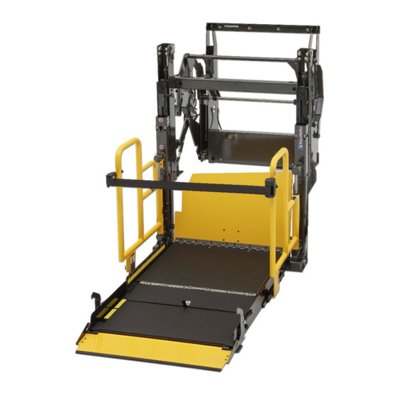
Page 4: Lift Terminology
Lift Terminology Mounting Pump Base Stow / Deploy Module Inner Hydraulic H Brace Vertical Cylinder Channel Intermediate Raise / Lower Vertical Channel Hydraulic (S-Beam) Cylinder (not visible) Outer Vertical Channel Outer Upper Control Arm Inner Inner Upper Roll Stop Control Arm Right Inner Handrail... -
Page 5: Switch And Sensor Locations
Switch and Sensor Locations Inner Roll Stop Up Activation Block Inner Roll Stop Occupied Switch Harn. 34700A Inner Roll Stop Deployed Floor Level Cam (Outer) 500-2015 Inner Roll Stop Deployed Floor Level Cam (Inner) 500-2014 Platform Unfold Microswitch 30205 Full In Microswitch Full Out 30205... - Page 6 403/404 compliant. If an operation does not func- the referenced procedures to correct the problem 571.404). or contact a Braun Corporation Product Support representative. 1. Verify lift door closed signal (vehicle interlock). 2. Refer to the interlock installation instructions.
-
Page 7: Switch Adjustments
Switch Adjustments Full In: point when the Inner Roll Stop is locked in the upright position. This deactivation stops the downward travel is stopped. Power is removed from the pump motor and triggers an alarm. and In Solenoid. The lift is fully stowed when the rubber bumpers are is also deactivated (depressed). - Page 8 Illustration at right. If any other value ap- harness is properly connected to both the control board and the associated lift harness. Repeat the harness diagnostic procedure. If an incorrect value is still present after check- The Braun Corporation Product Support Lift_Out Floor_SW Department. L CD MODULE...
- Page 9 NOTES This page intentionally left blank. Page 7...
- Page 10 Maintenance and Lubrication Lubrication Diagram Intermediate H-Brace Vertical Channel Pivot Points (2) (I-Beam) Edges (8) Inner / Outer Vertical Channel Roller Pins (56) Inner Roll Stop Slide Bracket Slot Area (2) (front & back) Upper Control Arms Pivot Points (12) Inner Roll Stop Lever Rollers (2) and Bearings (2)
-
Page 11: Maintenance And Lubrication Schedule
LPS2 General Purpose Penetrating Oil is recommended where Light Oil is Contact your sales representative or call The Braun Cor- called out. Use of improper lubricants can attract poration. One of our national Product Support represen-... - Page 12 Inspect all threaded fasteners for damage and posi- Resecure or replace damaged fasteners. See Ex- tive securement. ploded View section for fasteners that require #242 General Purpose Blue Loctite (Braun #18822). Remove pump module cover and inspect: nections for securement or damage Page 10...
- Page 13 Maintenance and Lubrication Schedule Resecure or replace if needed. Inspect cotter pins: Use Braun 32840-QT (Exxon ® Univis HVI 26) should be changed if there is visible contamination. lowered fully and roll stop unfolded fully. Measure Replace if needed. for visible wear or damage Inspect inner / outer vertical channel roller mount- Tighten or replace if needed.
- Page 14 NOTES This page intentionally left blank. Page 12...
-
Page 15: Lift Electrical Schematic
Lift Electrical Schematic DESCRIPTION SYMBOL BATTERY CHASSIS GROUND RD(20) CIRCUIT BREAKER / FUSE JUNCTION RD(20) MOTOR SOLENOID SOLENOID FULL OUT STOW LEVEL MICROSWITCH LIFT INPUTS MICROSWITCH SWITCH RD(18) BK(22) BK(18) RD(20) MICROSWITCH GN(22) DIODE RD(22) BU(22) RD(20) VT(22) BK(22) RD(22) GN(22) FULL IN WH(22) - Page 16 BK/OR(16) BK/OR(16) BK(16) ORANGE(26) RD(20) WHITE(26) ALARM OR(16) YL/RD(20) OR(16) RD(16) WHITE(20) 37258A BLACK(26) (Braun Replacement) 37107A YELLOW/RED (20) BLACK(20) NOT USED BK(16) BLUE(26) Switch Box Ultrasonic WH(16) Strobe / Alarm (As Viewed From Terminal Sensor Side of Switch) RD(16)
- Page 17 NOTES This page intentionally left blank. Page 15...
- Page 18 Hose Assembly, 46” x 1/4” Dia. - Swivel Ends 32785A-046 Hose Assembly, 48” x 1/8” Dia. - Swivel Ends 16004A-048 Hose Assembly, 9” x 1/4” Dia. - Swivel Ends 35987A-009 Knob, Knurled - Manual Valve 35088 Hydraulic Fluid use Braun 32840-QT (Exxon ® Univis HVI Page 16...
- Page 19 Hydraulic Diagram Arrow must face valve block Page 17...
- Page 20 Valve Block Housing Exploded View and Parts List DWG. NOTES 1) PLACE EYELET OF HARNESS ONTO BOLT B.C. #10006, THEN PLACE ONTO BLOCK B.C. #34571A-1 PRIOR TO PLACING INTO HOUSING. 2) AFTER VALVE BLOCK HAS BEEN INSTALLED, INSTALL KNOBS B.C. #35088 ONTO MANUAL VALVE STEMS AS SHOWN. NOTE: 2 NOTE: 1 *ITEMS NOT SHOWN...
- Page 21 Hand Pump Assembly Exploded View and Parts List DWG. NOTES 1) REMOVE BOLT AND NUT AND DISCARD. 2) INSTALL FITTINGS INTO PUMP B.C.#34572 PRIOR TO BOLTING TO BRACKET. NOTE: 1 ITEM PART NUMBER DESCRIPTION 87592 FITTING-90 DEG 4JICFX#4JICM 24504 FITTING-7/16-20/7/16-20/37° 14614 NUT-1/4-20 NYLOCK/AUTO-BK 10003...
-
Page 22: Hydraulic Schematic
Hydraulic Schematic .5 GPM Relief Valve 1500 Relief Valve 1500 Rear Front In/Out In/Out Cylinder Cylinder “B” Valve “C” “A” “D” Valve Valve Valve Valve Block Main Relief Valve 2000 PUMP 1900 Rear Front Up/Down Up/Down Cylinder Cylinder BACKUP Reservoir PUMP Description Symbol... -
Page 23: Mounting Base
Exploded Views and Parts Lists Mounting Base DWG. NOTES 1) APPLY " GREASE-MOBIL TEMP SHC 32 " B.C. #28598 TO ALL BEARINGS NOTED. 12x 2) APPLY ALCOHOL TO BRACKET B.C. #500-0018 PRIOR TO APPLYING BUMPERS B.C. #82064. 3) PLACE BOLT B.C. #10013 THRU EYELET OF CABLE B.C. #22166A PRIOR TO INSERTING THROUGH HOLE. -
Page 24: Upper / Lower Control Arms - Front
Exploded Views and Parts Lists Upper / Lower Control Arms - Front DWG. NOTES 1) APPLY " GREASE-MOBIL TEMP SCH 32 B.C. #28598 TO ALL BEARINGS. 2) APPLY LOCTITE ® THREADLOCKER BLUE 242 ® B.C.# 18822 TO B.C. #25171 10X AND 25527 1X. 3) TORQUE COLLAR TO: 144 in/lbs. -
Page 25: Upper / Lower Control Arms - Rear
Exploded Views and Parts Lists Upper / Lower Control Arms - Rear DWG. NOTES 1) APPLY " GREASE-MOBIL TEMP SCH 32 B.C. #28598 NOTE: 2 TO ALL BEARINGS. NOTE: 1 2) APPLY LOCTITE ® THREADLOCKER BLUE 242 ® B.C.# 18822 TO B.C. -
Page 26: Inner Vertical Channel - Front
Exploded Views and Parts Lists Inner Vertical Channel - Front DWG. NOTES 1) PARTS 500-0128 AND 500-0175A TO BE LOCATED TOWARD INSIDE OF CHANNEL 8X. 2) PARTS 500-0110 (6X) AND 500-3101A (6X) TO BE LOCATED TOWARD OUTSIDE OF CHANNEL. 3) APPLY " GREASE-MOBIL TEMP SCH 32 " B.C. #28598 TO INSIDE ROLLERS PRIOR TO ASSEMBLY 14X. -
Page 27: Inner Vertical Channel - Rear
Exploded Views and Parts Lists Inner Vertical Channel - Rear DWG. NOTES 1) PARTS 500-0128 AND 500-0175A TO BE LOCATED TOWARD INSIDE OF CHANNEL 8X. 2) PARTS 500-0110 (4X) AND 500-0301A (6X) TO BE LOCATED TOWARD OUTSIDE OF CHANNEL. 3) APPLY " GREASE-MOBIL TEMP SCH 32 " B.C. #28598 NOTE: 7 TO INSIDE ROLLERS PRIOR TO ASSEMBLY 14X. -
Page 28: Intermediate Vertical Channel (I-Beam) - Front
Exploded Views and Parts Lists Intermediate Vertical Channel (S-Beam) - Front DWG. NOTES 1) APPLY " GREASE-MOBIL TEMP SHC 32 " B.C. #28598 TO INSIDE ROLLER PRIOR TO ASSEMBLY. 2) APPLY LOCTITE ® THREADLOCKER BLUE 242 ® B.C. #18822 ON ALL THREADS DURING ASSEMBLY. NOTE: 1 3) HAND REAM CHAIN BLOCK HOLES WITH #21 (0.159”... -
Page 29: Intermediate Vertical Channel (I-Beam) - Rear
Exploded Views and Parts Lists Intermediate Vertical Channel (S-Beam) - Rear DWG. NOTES 1) APPLY " GREASE-MOBIL TEMP SHC 32 " B.C. #28598 TO INSIDE ROLLER PRIOR TO ASSEMBLY. 2) APPLY LOCTITE ® THREADLOCKER BLUE 242 ® B.C. #18822 ON ALL THREADS DURING ASSEMBLY. NOTE: 1 3) HAND REAM CHAIN BLOCK HOLES WITH #21 (0.159”... -
Page 30: Outer Vertical Channel - Front
Exploded Views and Parts Lists Outer Vertical Channel - Front DWG. NOTES 1) PARTS 500-0128 AND 500-0175A TO BE LOCATED 5) WIRE TO EXIT THROUGH TOP HOLE. TOWARD INSIDE OF CHANNEL 6X. 6) PLACE BEARING SURFACE OF ITEM 29378 NOTES: 2&3 2) PARTS 500-0110 AND 500-3101A TO BE LOCATED TOWARD SURFACE OF ITEM 500-0023. -
Page 31: Outer Vertical Channel - Rear
Exploded Views and Parts Lists Outer Vertical Channel - Rear DWG. NOTES 1) PARTS 500-0128 AND 500-0175A TO BE LOCATED TOWARD INSIDE OF CHANNEL 6X. NOTES: 2&3 2) PARTS 500-0110 AND 500-3101A TO BE LOCATED NOTE: 8 TOWARD OUTSIDE OF CHANNEL 8X. 3) APPLY "... -
Page 32: Handrail Assembly
Exploded Views and Parts Lists Handrail Assembly - Front DWG. NOTES 1) INSERT BOLT THROUGH CAM AND THREAD INTO SHAFT AFTER SHAFT HAS BEEN INSTALLED INTO HANDRAIL. 2) APPLY LOCTITE ® THREADLOCKER BLUE 242 ® B.C. #18822 ON ALL THREADS DURING ASSEMBLY. NOTE: 1 NOTE: 1 ITEM... - Page 33 Exploded Views and Parts Lists Platform Assembly DWG. NOTES 1) INSTALL PARTS B.C. #34357 AND B.C. 325371 AFTER OUTER PLATFORM IS INSTALLED INTO PLACE. 2) LOCATE SPRING HOOK INTO SPRING ATTACHMENT BRACKET ON THE BOTTOM SIDE OF THE PLATFORM INNER DECK. 3) USE (2) SCREWS FROM INNER ASSEMBLY AND RIVETS TO INSTALL GUARD INTO PLACE.
- Page 34 Exploded Views and Parts Lists Platform Sub-Assembly - Inner DWG. NOTES 1) APPLY LOCTITE ® THREADLOCKER BLUE 242 ® B.C. #18822 ON ALL THREADS DURING ASSEMBLY. 2) APPLY "GREASE-MOBILTEMP SHC 32" B.C.#28598 TO PULLEY INNER HOLE AND INSERT INTO SLOT BEFORE BOLTING INTO PLACE. 3) PLACE HINGE B.C.
- Page 35 Exploded Views and Parts Lists Platform Sub-Assembly - Inner Side Plate (Front) DWG. NOTES 1) USE LOCTITE ® THREADLOCKER BLUE 242 ® B.C.# 18822 ON ALL THREADS DURING ASSEMBLY. ITEM QTY. PART NO. DESCRIPTION 500-0156 HANDRAIL SUPPORT BRACKET 81027-000 SCREW-1/4-20 X 1-1/4 FHSC 25527 SCREW-5/16-18 X 3/4 "...
- Page 36 Exploded Views and Parts Lists Platform Sub-Assembly - Outer DWG. NOTES 1) USE LOCTITE ® THREADLOCKER BLUE 242 ® B.C.# 18822 ON ALL THREADS DURING RE ASSEMBLY. 2) ROUTE HARNESS THRU STRAIN RELIEF (ITEM #40). 3) ROUTE HARNESS THRU CLAMP (ITEM #30). NOTE: 3 NOTE: 2 ITEM...
-
Page 37: Braun Limited Warranty
The warranty period begins of Braun, or, if the dealer places the product into any type of service prior to retail sale, on the date the may not be transferred. - Page 38 WHAT IS NOT COVERED the product not attributable to Braun, any material, component or part of the product that is warranted by another entity (Note: the written warranty provided by the manufacturer of the material, component or part components or parts.
- Page 39 LEGAL REMEDIES only sets forth what Braun will do and does not guarantee anything about the product for any time period. in the statute of limitations, so this reduction may not apply to you. WARRANTY REGISTRATION and MISCELLANEOUS Your warranty registration records should be completed and delivered to the appropriate companies, includ- ing the Braun Delivery Checklist &...
- Page 40 NOTES This page intentionally left blank. Page 38...
- Page 41 "Providing Access to the World" ® Over 300 Braun Dealers Worldwide ® "Providing Access to the World" International Corporate Hdqrs: P .O. Box 310 Winamac, IN 46996 USA 1-800-THE LIFT ® (574) 946-6153 FAX: (574) 946-4670...
- Page 42 All illustrations, descriptions and specifications in this manual are based on the latest product information available at the time of publication. The Braun Corporation reserves the right to make changes at any time without notice. at the time of publication. The Braun Corporation reserves the right to make changes at any time without notice.
Need help?
Do you have a question about the NL502 Series and is the answer not in the manual?
Questions and answers