
Related Manuals for Blue Wave HYDRO NE635


Summary of Contents for Blue Wave HYDRO NE635
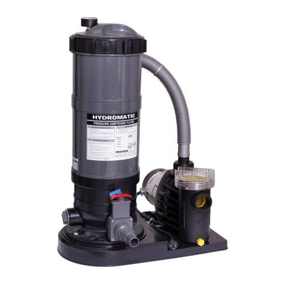
- Page 1 PRESSURE CARTRIDGE FILTER INSTRUCTIONS TOOLS REQUIRED 1. Flat Head Screwdriver 2. Pliers NE635, NE636 6329...
-
Page 2: Parts Identification
PARTS IDENTIFICATION 1. OPEN CARTON #1 AND UNPACK THE FILTER TANK A. Remove all packing material from filter carton. B. Open tank, remove any packing materials and inspect cartridge. 2. OPEN CARTON #2 AND UNPACK ALL COMPONENTS A. Filter base B. -
Page 3: Pre-Assembly
3. PRE-ASSEMBLY Hooking up the filter and motor to the base will vary based on the style of pump you have. Please note that steps 4A, 4B, or 4C will help you determine the style of pump and proper hook-up to the base. Prior to attaching the filter or pump to the base, locate one of the slide valves (I). - Page 4 4A. CRADLE STYLE MOUNT Pumps with cradles located directly under the motor (see Figure 2) should be aligned with the holes inside the raised area of the base (see Figure 3a). This type of mount will require the use of FOUR mounting bolts from the hardware bag (H).
- Page 5 4B. PLASTIC PUMP HOUSING MOUNT Pumps with plastic pump housing mounts (see Figure 7) should be attached by aligning the openings with the two holes outside the raised area (see Figure 8a). This type of mount will require the use of TWO mounting bolts from the hardware bag (H).
- Page 6 4C. SIDE-MOUNT PUMPS Side-mount pumps (see Figure 12) allow you to attach the pump DIRECTLY to the filter body. Prior to attaching the pump, you must attach the tank to the base in order to determine which set of holes to use for the pump. Figure 12 —...
- Page 7 5. ATTACHING FITTINGS & HOSES TO YOUR PUMP & FILTER There are several ways to hook up hoses to your filter and pump and the best way will depend on your set-up. Some pumps have female threads only (inside), some have male threads only (outside) and others may have both or none.
- Page 8 If your pump has threads on the outside of the outlet (top of the pump) then you will thread one of the connection fittings directly onto it. Thread opposite side directly onto the “FROM PUMP” port of the filter and hand tighten connection (see Figures 21 & 22). Figure 21 —...
- Page 9 6. USING SLIDE VALVES The slide valves are used to stop the flow of water to the filter for routine maintenance. While the filter is in operation, the slide valves MUST remain in the open position To open the valve, turn the red handle to the left and pull straight up (see Figure 23a for open valve).
- Page 10 R E E E A A A D D D A A A N N N D D D F F F O O O L L L L L L O O S A A A F F F E E E T T T Y Y Y I I...
-
Page 11: General Information
GENERAL INFORMATION Hazardous pressure. If filter is improperly disassembled or assembled, it will explode under pressure. D A A A N N N G G G E E E R R To avoid danger of severe injury or major property damage, always follow service instructions in this manual (Pages 11 to 13) when working on filter. -
Page 12: Installation - General
INSTALLATION — GENERAL FILTER LOCATION SHOULD: • Provide space and lighting for easy access for routine maintenance. • Provide adequate ventilation and drainage for pump. • Be reasonably level. • Be as close to pool as possible to reduce line loss from pipe friction. PIPING •... - Page 13 ASSEMBLING FILTER Filter Cartridge may shift position during shipping. To make sure cartridge is in place, follow procedure below before using filter. When disassembling filter, place all parts in a clean area. 1. Place filter in a clean area near its permanent location. 2.
- Page 14 START UP HAZARDOUS PRESSURE. Risk of severe injury or major property damage if tank explodes. READ the WARNING entire procedure before starting system or disassembling filter. 1. Turn pump OFF before starting procedure. 2. Properly seat filter clamps and securely tighten clamp knobs before proceeding. 1.
-
Page 15: Filter Disassembly
FILTER DISASSEMBLY Releasing either ring with pressure on system will cause tank or tank head to blow off base, causing severe D A A A N N N G G G E E E R R injury or major property damage. NEVER adjust, tighten or loosen ring when tank is under pressure. If filter Hazardous Pressure leaks at the ring, do not adjust the ring. -
Page 16: Filter Cleaning Procedure
FILTER REASSEMBLY LIFT FILTER ELEMENT STRAIGHT UPWARD TO REMOVE 1. Replace plugs or close valves in Tank Drain and Auxiliary Drain ports. 2. Set filter element on base. 3. Make sure filter element is flush with base of filter to avoid damaging element when you replace the filter head (Figure 3). -
Page 17: Special Cleaning Instructions
SPECIAL CLEANING INSTRUCTIONS Risk of fire or explosion. Isolate filter from system before chemical cleaning; rinse filter and elements D A A A N N N G G G E E E R R completely before returning to service. If filter cannot be isolated, remove media and clean at another location. Follow chemical manufacturer’s instructions for use. Do not mix chemicals except as directed by manufacturer. -
Page 18: Troubleshooting Guide
WINTERIZING Hazardous pressure. To avoid severe injury or major property damage, follow instructions below exactly. D A A A N N N G G G E E E R R Explosion hazard. Purging the system with compressed air can cause components to explode, with risk WARNING of severe injury or death to anyone nearby. - Page 19 LOW FLOW: 1. Element is plugged — see “Special Cleaning Instructions”. 2. Pipe blocked downstream from filter — remove obstruction. 3. Piping too small — replace with larger pipe (consult dealer for recommendation). 4. Pump hair and lint trap is plugged — empty and clean. 5.
- Page 20 FILTER PARTS LIST PART # DESCRIPTION PRC30 PRC60 PRC90 PRC120 PRC150 PRC180 PRC30BD PRC60BD PRC90BD PRC120BD PRC150BD PRC180BD NE635 NE636 BS 40061BLK Hose Adapter BS PRCBASE Filter Base AC 26875 Complete LID AC 26859 Slide Valve BS 10022 6’ 1/2 Hose BS 17396GRY Threaded Plug BS 35815 Clamps...
- Page 21 No warranty claim will be honored without a receipt. Please notify Blue Wave Products in advance of any Hydro™ warranty claim prior to shipping the item back. Contact our warranty claim department at warranty@splashnetxpress.com.
Need help?
Do you have a question about the HYDRO NE635 and is the answer not in the manual?
Questions and answers
Is there a chart or a way to figure out pipe size if you want to have the filter a distance from the pool