Table of Contents
Advertisement
Quick Links
Installation and
Operating Instructions
for use by engineers and heating contractors
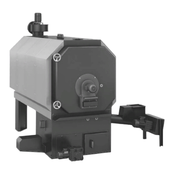
Vitoflex 300-RF 150, 220, 300, 400 and 540
Wood-fired Boiler
Output range: RF 150 154 to 512 MBH (45 to 150 kW)
RF 220 205 to 751 MBH (60 to 220 kW)
RF 300 273 to 1024 MBH (80 to 300 kW)
RF 400 341 to 1365 MBH (100 to 400 kW)
RF 540 478 to 1843 MBH (140 to 540W kW)
Vitoflex 300-RF
5797 340 - 01 08/2017
IMPORTANT
Please ensure that these instructions are
read and understood before commencing
installation and start-up. Failure to comply
with these Installation Instructions will
render all warranties null and void.
Working on the equipment
The installation, adjustment, service and
maintenance of this product must be
performed by a licensed professional heating
contractor, who is qualified and
experienced in the installation, service
and maintenance of hot water heating
boilers. There are no user serviceable
parts on the boiler or control.
Ensure main power supply to equipment,
the heating system and all external
controls has been deactivated.
Take precautions in all instances to avoid
accidental activation of power during
service work.
Improper installation, service or
maintenance can cause product/property
damage, severe personal injury, and/or
loss of life.
Product may not be exactly as shown
IMPORTANT
Read and save these instructions
.
for future reference
Please file in Service Binder
Advertisement
Table of Contents

Related Manuals for Viessmann Vitoflex 300-RF Series


Summary of Contents for Viessmann Vitoflex 300-RF Series
- Page 1 Installation and Operating Instructions for use by engineers and heating contractors Vitoflex 300-RF 150, 220, 300, 400 and 540 Wood-fired Boiler Output range: RF 150 154 to 512 MBH (45 to 150 kW) RF 220 205 to 751 MBH (60 to 220 kW) RF 300 273 to 1024 MBH (80 to 300 kW) RF 400 341 to 1365 MBH (100 to 400 kW) RF 540 478 to 1843 MBH (140 to 540W kW)
-
Page 2: Safety, Installation And Warranty Requirements
“Safety” section. All inhabitants and destructive to Viessmann equipment. products of combustion must be safely vented to the outdoors. For a listing of chemicals which... -
Page 3: About These Instructions
This symbol indicates to note additional information This symbol indicates that other instructions must be referenced. Note: Viessmann Manufacturing Company Inc. reserves the right to make product changes or updates without notice and will not be held liable for typographical errors or omissions in the product literature. -
Page 4: Table Of Contents
Table of Contents Vitoflex 300-RF Installation & Operating Page Introduction Safety, Installation and Warranty Requirements....2 About These Instructions..........3 General Information Important Regulatory and Installation Requirements ..6 Codes..............6 Mechanical room...........6 Working on the equipment........6 Technical literature..........6 Product Information.............7 Boiler Description............8 Transport and Installation..........9 Delivery Condition.............10 Standard delivery condition........10 Special delivery condition........11... - Page 5 Table of Contents Vitoflex 300-RF Installation & Operating Page Mechanical (continued) Fire Extinguishing Systems........36 Assembly of the Fire Extinguishing Systems....37 Control Panel............38 Mounting of the control panel........38 Electrical connection..........38 General safety instructions........38 Operation Appliance Description..........39 Operating States............41 Programming Unit........,,,,,,..42 Default Display............43 Manual Mode and Calling up Further Information..46 Parameters...............46 Menu..............46...
-
Page 6: General Information
Leave all literature at the installation site and advise Literature applicable to all aspects of the Vitoflex 300-RF the system operator/ultimate owner where the wood-fired boiler: literature can be found. Contact Viessmann for - Installation and Operating Instructions additional copies. - Service and Maintenance Instructions ... -
Page 7: Product Information
General Information Vitoflex 300-RF Installation & Operating Product Information Maximum allowable working pressure (water)...30 or 60 psi Viessmann solid-fuel boiler may only be installed and serviced by trained personnel. Maximum water temperature…..250°F (120°C) (closed loop) Steel wood-fired hot water heating boiler. -
Page 8: Boiler Description
General Information Vitoflex 300-RF Installation & Operating Boiler Description Boiler Description Description Supplied with: The Vitoflex 300-RF Rotating Combustion System (pat- - Boiler with rotary heat exchanger including supply and ent no: EP 0 905 442 B1) was developed for automatic return temperature sensors combustion wood, pellets and wood chips to max. -
Page 9: Transport And Installation
General Information Vitoflex 300-RF Installation & Operating Transport and Installation IMPORTANT Precautions must be taken to avoid accidents and injury during the transportation of the boiler. Only hoist the boiler when it is entirely empty of water, fuel and ash. Lifting A number of lifting lugs will be provided on each boiler and heat exchanger where lifting gear may be attached. -
Page 10: Delivery Condition
General Information Vitoflex 300-RF Installation & Operating Delivery Condition Standard delivery condition The standard delivery condition of the Vitoflex 300-RF boiler includes pre-assembled components as well as components that need to be assembled by the contractor in the field. Components that are attached to the boiler at time of delivery: - The heat exchanger is mounted to the combustion chamber - Boiler is fully bricked - Boiler door is mounted to the heat exchanger including secondary air rotating blower... -
Page 11: Special Delivery Condition
General Information Vitoflex 300-RF Installation & Operating Delivery Condition (continued) Special delivery condition (partially disbanded) For special circumstances like restricted space to bring the boiler into the heating room, the size of the boiler can be reduced by detaching additional components to the ones as described in section “Standard delivery condition”. The assembly of these components require additional assembly time of approximately 6 hours. -
Page 12: Wood Fuel Requirements
The Vitoflex 300-RF is only suitable for burning fuels IMPORTANT listed in this section. A prerequisite for approval is of a fuel by Viessmann is the If different fuels are used, Viessmann will not assume approval for the fuel by the responsible public authorities. -
Page 13: Maximum Water Content
General Information Vitoflex 300-RF Installation & Operating Wood Fuel Requirements (continued) Maximum water content The maximum allowable water content of the fuel for Vitoflex 300-RF systems is limited to 35%. The water content impacts the maximum boiler output. Non-wood fuels Non-wood fuels, even if consisting of biomass, such as needles, foliage, grain, straw, fruit pits, etc., are unsuited as fuel for boiler operation and may not be used. -
Page 14: Content Limits For Non-Combustable Substances
General Information Vitoflex 300-RF Installation & Operating Wood Fuel Requirements (continued) Content limits for non-combustible substances - No wood fuels may contain any foreign bodies, such as pieces of metal, stones, masonry remnants or plastics. The following limits (per lb/kg of dry fuel) of contained non-combustible substances apply [ash analyzed at a temperature of 1500°F (815°C)]: Substance Limit... -
Page 15: Safety
Failure Note: Viessmann does not test any detectors and makes to heed this warning can cause property damage, no representation regarding any brand or type of severe personal injury, or loss of life. -
Page 16: Hazardous Materials
Safety Vitoflex 300-RF Installation & Operating Hazardous Material Fiberglass wool and ceramic fiber materials First aid measures - If eye contact occurs, flush eyes with water to remove dust. If symptoms persist, seek medical attention. WARNING - If skin contact occurs, wash affected areas gently with Inhaling of fiberglass wool and/or ceramic fiber materials soap and warm water after handling. -
Page 17: Power Failure Provision
Safety Vitoflex 300-RF Installation & Operating Power Failure Provision Customers must ensure that there is a supply of water independent of the electrical supply. This design ensures that in case of a power failure, the boiler will be reliably cooled by the thermal safety flush valve. Backup power supply or backup generator is highly recommended to ensure continuous operation in the event of power failure. -
Page 18: Mechanical Room
The load-bearing capacity of the floor in Viessmann recommends the installation of an additional the area of the boiler bearing surface must be 512 lb/ft² electrical disconnect switch and a fuel shut-off valve (if (2500 kg/m²). -
Page 19: Mechanical Room Conditions
Safety Vitoflex 300-RF Installation & Operating Mechanical Room (continued) IMPORTANT WARNING Components which are not tested with the heating system Incorrect ambient conditions can lead to damage to the may damage the heating system or affect its functions. heating system and put safe operation at risk. Installation or replacement may only be carried out be a qualified heating contractor. -
Page 20: Combustion Air Supply
Safety Vitoflex 300-RF Installation & Operating Combustion Air Supply Confined spaces Codes When a furnace or boiler is enclosed in a space that has Provision for combustion and ventilation air must be made a volume less than 20% of that to be heated by the in accordance with applicable local codes. -
Page 21: Mechanical
Mechanical Vitoflex 300-RF Installation & Operating Technical Data Boiler model RF 150 RF 220 RF 300 RF 400 RF 540 Maximum output MBH (kW) 512 (150) 751 (220) 1024 (300) 1365 (400) 1843 (540) Minimum output MBH (kW) 154 (45) 205 (60) 273 (80) 341 (100) -
Page 22: Boiler Dimensions
Mechanical Vitoflex 300-RF Installation & Operating Boiler Dimensions BR Boiler Return BS Boiler Supply Dimensions Boiler Model RF- in. (mm) (392) 16 (406) 16 (406) 18e (466) 18e (466) 7 / 16 in. (mm) 60f (1541) 60 (1525) (1875) (1800) (2030) 13 / 16 7 / 8... - Page 23 Mechanical Vitoflex 300-RF Installation & Operating Boiler Dimensions (continued) Legend A Boiler Return B Boiler Supply C Automatic de-ashing system (optional) Dimensions Boiler Model RF- in. (mm) (3415) (3685) 119b (3035) 120b (3059) 136d (3457) 7 / 16 1 / 16 in.
-
Page 24: Boiler Components
Mechanical Vitoflex 300-RF Installation & Operating Boiler Components Legend A Pneumatic cleaning system (optional) B Cleaning cover, flue gas collector, alternate port for the flue gas exhaust blower C Cover with sight glass D Recirculation gas line, line routing variable E Igniter F Rotary blower G Flue gas temperature sensor... -
Page 25: Recirculation System
Mechanical Vitoflex 300-RF Installation & Operating Recirculation System Legend A Vent piece with recirculation adaptor B Recirculation system damper C Threaded rod M12 39e in. (1000 mm) D Base plate M12 (x4) E Pipe clamp M12 (x4) F Pipe clamp fitting (x16) G Elbow 15º... -
Page 26: Chimney Connection
Mechanical Vitoflex 300-RF Installation & Operating Chimney Connection It is recommended to install a draft damper in the chimney The draft damper is field supplied. The optional draft damper can be installed in the flue gas pipe of the biomass boiler The draft damper should be installed in the flue gas pipe as close as possible to the chimney not closer than 39e in. -
Page 27: Flue Gas Cyclone
Mechanical Vitoflex 300-RF Installation & Operating Flue Gas Cyclone The flue gas cyclone minimizes dust emissions and is Supplied with: designed as a multi cyclone with axial function. 1 flue gas cyclone ■ The de-duster is fully insulated and has three covers for 1 ash container 24 USG (90 L) ■... -
Page 28: Metal Mesh Filter
Mechanical Vitoflex 300-RF Installation & Operating Metal Mesh Filter The metal mesh filter removes dust and fine dust from the Supplied with: flue gas. It is characterized by a particularly high degree - Two-part, insulated filter casing with: of separation. This ensures a fine dust content of less - Hinged doors, lockable by means of a quick-action than 20 mg/Nm in the clean gas. - Page 29 Mechanical Vitoflex 300-RF Installation & Operating Metal Mesh Filter (continued) Legend A Clean gas collector B Crude gas distributor (connection possible on both sides) C Recirculation gas connection D Clean gas to chimney E Crude gas from boiler (connection possible on both sides) F Flue gas exhaust blower (with variable rotation) (alternate mounting of flue gas blower shown in dark grey) G Control panel Ecocontrol...
-
Page 30: Safety Devices
Mechanical Vitoflex 300-RF Installation & Operating Safety Devices Boiler system with return 3-way mixing valve 1. Install the pressure relief valve, discharge pipe, air vent and pressure gage as illustrated in section piping To reliably prevent boiler corrosion through condensation and installation of safety devices. - Page 31 Mechanical Vitoflex 300-RF Installation & Operating Safety Devices (continued) The safety equipment for the heating installation must be installed by the heating contractor authorized to do so. Legend L Safety heat exchanger connections, NPTM b in. A Nipple, c in. x 1b in. M Sensor well - fixed high limit B Reducing coupling, c in.
-
Page 32: Piping And Installation Of Safety Devices
Mechanical Vitoflex 300-RF Installation & Operating Piping and Installation of Safety Devices System fill Drain inspection port System fill Safety heat exchanger top view 3-Way mixing valve System return line Blocked 2 heat exchanger port loops for Bypass line Vitoflex 300-RF 400/540 Valve adjustment must be facing forward... - Page 33 - PDP pressure relief valve drain pipe be below 150°F (65°C). - DCW Cold water inlet, min. 36 psi (2.5 bar), max. A Viessmann sized boiler pump with a boiler 51 psi (3.5 bar) 3-way mixing valve are provided according to the - AV Air separator / vent tables below.
-
Page 34: Fire Protection
RF 300 3 in. 3-way mixing valve RF 400 3 in. 3-way mixing valve RF 540 4 in. 3-way mixing valve Viessmann ASME recommended tank sizes (U-stamped) Boiler model Tank size RF 150 1514 RF 220 2006 RF 300 2650... -
Page 35: Back-Burn Safeguard For The Fuel Supply System
Fire protection for fuel storage space unit and the boiler. The rotary valve is suited to reduce Viessmann does not provide fire protection for the fuel pressure and at the same time is considered a suitable storage space. -
Page 36: Fire Extinguishing Systems
Mechanical Vitoflex 300-RF Installation & Operating Fire Extinguishing Systems The fire extinguishing system functions independent from Fire extinguishing system for the conveyor auger the electrical power and is flooding the material which is Note: The fire extinguishing system for the conveyor still remaining in the in-feed auger in case of a back-burn. -
Page 37: Assembly Of The Fire Extinguishing Systems
Mechanical Vitoflex 300-RF Installation & Operating Assembly of the Fire Extinguishing System deburr drill hole Connection to the extinguishing water container or cold water supply piping (field supplied). Item No. Quantity Description Item No. Quantity Description Connector b in. Floater switch (N1) Danfoss AVTA Washer Reducer c in. -
Page 38: Control Panel
(10°C). In case of doubt, preference should be given to placing the control panel outside the mechanical room The Viessmann supplied field wiring diagram is not a near the heating room door. complete system drawing. It is the installer’s responsibility... -
Page 39: Appliance Description
Operation Vitoflex 300-RF Installation & Operating Appliance Description The Vitoflex 300-RF is an automatic solid fuel boiler with rotation combustion. The boiler is made of steel. The lower section contains the infeed grate. The rotation combustion takes place in the combustion chamber above. The Vitoflex 300-RF is designed for automatic fuel combustion. - Page 40 Operation Vitoflex 300-RF Installation & Operating Appliance Description (continued) Controller The system controller regulates and controls the combustion system and all associated components. Fuel supply The fuel is transported via the feed on to the infeed grate. A feed screw conveyor is installed at the side for this purpose.
-
Page 41: Operating States
Operation Vitoflex 300-RF Installation & Operating Operating States In automatic mode, the boiler assumes various operating states as listed in the following table. The relevant current operating state is displayed on the programming unit. The order of the operating states normally follows the sequence detailed in the table, from “OFF”... -
Page 42: Programming Unit
Operation Vitoflex 300-RF Installation & Operating Programming Unit The programming unit is equipped with a touchscreen. To input settings and call up information, tap the on- screen buttons. Legend A Touchscreen B Green LED This LED is lit when the controller is in operation. C Red LED This LED flashes while the controller is ramping up. -
Page 43: Default Display
Operation Vitoflex 300-RF Installation & Operating Programming Unit (continued) Number pad Legend A ESC key The number pad is closed and no data is saved. B Entry field Contents can be changed by tapping in the box by means of the number pad. C Enter key Saves the entered data and closes the number pad. - Page 44 Operation Vitoflex 300-RF Installation & Operating Default Display (continued) Legend A “Fuel” Displays fuel supply in % B “Secondary air” Displays flue gas oxygen content in % C “Flow” Displays flow temperature in °C D “Flue gas fan” Displays flue gas fan utilisation level in % E “Flue gas temperature”...
- Page 45 Operation Vitoflex 300-RF Installation & Operating Default Display (continued) Header and footer on the programming unit Header “Menu” This takes you to the menu screen, see page 46. System is currently switched on. You can switch the system off. System is currently switched off. You can switch the system on. No faults in the system System fault “Load”...
-
Page 46: Manual Mode And Calling Up Further Information
Operation Vitoflex 300-RF Installation & Operating Manual Mode and Calling up Further Information The “Boiler”, “Auxiliary systems” and “Heat distribution” sub-area screens show the set values and actual values, as well as status information for the selected sub-area. The Manual mode and Automatic mode buttons enable you to operate components manually or automatically. -
Page 47: Information On Starting Up/Shutting Down
Operation Vitoflex 300-RF Installation & Operating Information on Starting Up/Shutting Down WARNING CAUTION Risk of burns due to hot system components. Risk of injury due to untrained personnel. Only touch handles and identified parts. Only allow trained and experienced personnel to operate Never touch sight glasses or their retainers. -
Page 48: Parameter Level
Parameters Vitoflex 300-RF Installation & Operating Parameter Level On each sub-area screen, the button gives you access to the sub-area’s parameter level. The parameters may be assigned to several tabs. The number of parameters varies depending on the system configuration. Parameters are set using the entry fields. Charging “Feed”... - Page 49 Parameters Vitoflex 300-RF Installation & Operating Charging (continued) Parameters Description Setting in Setting Default range value “Delay, O2, heatup” Length of time for which ignition is monitored in the seconds 50 to 300 “Ignition” operating state If the O value falls below 15 % for the set time, the boiler switches to the “Load”...
- Page 50 Parameters Vitoflex 300-RF Installation & Operating Charging (continued) “Charging” tab Parameters /column Description Setting in “Delay ON” Start delay for the component seconds “Delay OFF” Shutdown delay seconds “Pulse” On/off times for the component’s operation: seconds - Pulse = Component is on “Pause”...
- Page 51 Parameters Vitoflex 300-RF Installation & Operating Charging (continued) Parameters Description Setting in Setting Default range value “Emergency mode” “Pulse” If the runtime monitoring function for the transverse seconds 0 to 100 screw conveyor is triggered, it is assumed that bridging “Pause”...
- Page 52 Parameters Vitoflex 300-RF Installation & Operating Charging (continued) “Fill levels” tab Display Description “Interrupted” If the light barrier is triggered, the message “Interrupted” or “Full” is displayed for all parameters and the status indicator is not illuminated. “full” Parameters Description “Firebed 1”...
- Page 53 Parameters Vitoflex 300-RF Installation & Operating Charging (continued) “Ash removal” tab Parameters Description Setting in Setting Default range value “Infeed grate, pause” Pause time of the infeed grate under full load seconds 0 to 500 “Infeed grate pause, Pause time of the infeed grate under partial load seconds 0 to 500 partial load”...
-
Page 54: Secondary Air
Parameters Vitoflex 300-RF Installation & Operating Secondary Air The secondary air parameters are used to determine the heating output. The amount of secondary air regulates the oxygen content in the flue gas. Secondary air is blown in via the door. If the set value for the amount of secondary air is exceeded, the amount of fuel supplied is reduced. -
Page 55: Flow
Parameters Vitoflex 300-RF Installation & Operating Flow “Settings” tab Parameters Description Setting in Setting Default range value “Flow temperature” Supply temperature (°F) (167 to 203) (185) °C 75 to 95 “Return temperature, Minimum return temperature (°F) °C Min. setting minimum” 65°C (149°F) Note: max. - Page 56 Parameters Vitoflex 300-RF Installation & Operating Flow (continued) “Controller” tab “Flow controller” Parameters Setting range Default value “P factor” 1 to 100 “D factor” 1 to 100 “Cycle time” 1000 to 15000 5000 “Return controller” Parameters Setting range Default value “P factor”...
-
Page 57: Flue Gas Fan
Parameters Vitoflex 300-RF Installation & Operating Flue Gas Fan “Settings” tab Parameters Description Setting in Setting Default range value “Start speed, flue Speed of the flue gas fan when the system is switched on “Minimum gas fan” speed, flue gas fan” to “Maximum speed, flue gas fan”... -
Page 58: Buffer Tank
Parameters Vitoflex 300-RF Installation & Operating Buffer Tank “Temperatures” tab Parameters Description Setting in Setting Default range value “Operating mode” Set operating mode of buffer tank “ Köb” “ Köb” “Boiler start at Setting specifies which sensor the boiler should start at “... -
Page 59: Boiler 2
Parameters Vitoflex 300-RF Installation & Operating Boiler 2 “Temperatures” tab Parameters Description Setting in Setting Default range value “Operating status” Displays the current operating state of additional boiler “Start at Start temperature of Boiler 2 (°F) (122 to 203) (158) temperature °C 50 to 95... -
Page 60: Dhw Circulation 1
Parameters Vitoflex 300-RF Installation & Operating DHW Circulation 1 “Temperatures” tab Parameters Description “Operating mode” Displays the set operating mode for DHW circulation “Operating status” Displays the current operating state for DHW circulation Set heating times 1. In the “Heating period 1” line, tap on the “Start” column. -
Page 61: Dhw Tank 2
Parameters Vitoflex 300-RF Installation & Operating DHW Tank 2 “Temperatures” tab Parameters Description Setting in Setting Default range value “Operating mode” Displays the set operating mode of the DHW tank “Set DHW Set temperature for DHW (°F) (104 to 176) (140) temperature”... -
Page 62: Heating Circuit 3
Parameters Vitoflex 300-RF Installation & Operating Heating Circuit 3 “Temperatures” tab Parameters Description Setting in Setting Default range value “Operating mode” Displays the set operating mode for heating “Operating status” Displays the current operating state for heating “Set flow at +10°C” Set supply temperature at plus 10°C (18°F) outside (°F) (68 to 194) -
Page 63: Cleaning The Touchscreen
Further Settings Vitoflex 300-RF Installation & Operating Cleaning the Touchscreen Tap the following on-screen buttons: 1. “Menu” 2. “Panel” 3. “Cleaning screen” The touchscreen is inactive for 15 seconds and can be touched without effect. 4. Clean touchscreen. Setting the Language Tap the following on-screen buttons: 1. -
Page 64: Parameter Set Management
Further Settings Vitoflex 300-RF Installation & Operating Parameter Set Management Managing the parameter sets Parameter sets allow you to save parameters specific to a particular fuel and load them again at a later date. Tap the following on-screen buttons: 1. “Menu” 2. -
Page 65: Ip Settings
Further Settings Vitoflex 300-RF Installation & Operating IP Settings By entering the correct IP settings, you can link the controller into a network. Tap the following on-screen buttons: 1. “Menu” 2. “Special functions” 3. “IP settings” The following screen opens: Displaying your own network settings Most networks have an integral DHCP server. -
Page 66: User Administration
Further Settings Vitoflex 300-RF Installation & Operating User Administration Tap the following on-screen buttons: 1. “Menu” 2. “User administration” The following screen opens. Column Description Name Name User name entry fields Password Password entry fields You can manage users from this screen. You can create up to 5 users in each user group. -
Page 67: Diagrams
Further Settings Vitoflex 300-RF Installation & Operating Diagrams You can have up to 4 parameters (actual and set values) displayed in a diagram. The values are stored in a 30 min ring buffer. For this, values are recorded every 10 sec. Opening diagrams Tap the following on-screen buttons: 1. - Page 68 Further Settings Vitoflex 300-RF Installation & Operating Diagrams (continued) Diagram settings Legend A List of parameters Overview of all parameters which can be shown in the diagrams. Tap on “Overview” or to open or close the list of parameters. Tap on a parameter. The parameter is highlighted with a blue background and is selected.
-
Page 69: Period
Further Settings Vitoflex 300-RF Installation & Operating Shutting Down the Heating System for an Extended Period 1. Switch off the system via the button. The controller switches the system off automatically. 2. Allow the existing firebed to burn out completely. WARNING There is a risk of deflagration when the combustion chamber door is opened. -
Page 70: Sub-Area Screens For The Boiler
Further Settings Vitoflex 300-RF Installation & Operating Sub-area Screens for the Boiler The sub-area screens are accessed from the default display, via buttons “Fuel”, “Secondary air”, “Flow” and “Flue gas fan”. Fuel Legend A Displays boiler output in % B “Fuel supply” Green arrow is animated: Fuel supply active ___/”empty”: Light barrier for firebed is clear ___/”full”: Light barrier for firebed is interrupted... -
Page 71: Sub-Area Screens For The Auxiliary Systems
Further Settings Vitoflex 300-RF Installation & Operating Sub-area Screens for the Boiler (continued) Flue gas fan Legend A Displays flue gas fan utilisation level in % B “Flue gas fan” Fan is animated: Flue gas fan active Sub-area Screens for the Auxiliary Systems The screen for the auxiliary system can be accessed from the default display via the button. - Page 72 Further Settings Vitoflex 300-RF Installation & Operating Sub-area Screens for the Auxiliary Systems (continued) Buffer tank Legend A Displays actual and set return temperature in °C B Displays actual and set fill level temperature in °C C “Return mixer” Displays return mixer setting button: Activate manual mode for return mixer button: Activate automatic mode for return mixer Default set value...
- Page 73 Further Settings Vitoflex 300-RF Installation & Operating Sub-area Screens for the Heat Distribution The screen for heat distribution can be accessed from the default display via the button. Legend A “DHW circulation 1” B “DHW cylinder 2” Displays actual temperature in °C C “Heating circuit 3”...
-
Page 74: Sub-Area Screens For The Heat Distribution
Further Settings Vitoflex 300-RF Installation & Operating Sub-area Screens for Heat Distribution DHW cylinder 2 Legend A Displays valve setting in % B Displays actual and set temperature in °C C Displays operating mode setting button: Activate manual mode button: Activate automatic mode Heating circuit 3 Legend A Displays valve setting in %... -
Page 75: Boiler Wiring
Boiler Wiring CAUTION CAUTION The Viessmann supplied field wiring diagram is not a The information about wire type, wire number and wire complete system drawing. It is the installer’s responsibility gauge made in the wiring diagrams is not obligatory. The... -
Page 76: Commissioning
Commissioning Initial start up Water quality Only a Viessmann or another trained specialist may put Treatment for boiler feed water should be considered a newly installed system into operation for the first time. in areas with known problems, such as where a high Before the system is commissioned, the system must be mineral content and hardness exist. -
Page 77: Filling The Fuel Storage Unit
As soon as the articulated arms or spring-mounted plates have retracted through Note: Viessmann recommends the installation of carbon a request for material, the refilling can be continued. monoxide detector(s) inside the fuel storage area. -
Page 78: Excess Conditions
Operation Vitoflex 300-RF Installation & Operating Excess Conditions Low water/excess water pressure IMPORTANT Possible causes: - Low water: Leakage in the heating system. Excess temperature/power failure - Excess water pressure: The expansion tank is not functioning. CAUTION In either case, the boiler should be examined by a qualified DANGER OF THIS EQUIPMENT SUDDENLY GOING UP heating contractor. - Page 79 Vitoflex 300-RF Installation & Operating...
- Page 80 Vitoflex 300-RF Installation & Operating...
Need help?
Do you have a question about the Vitoflex 300-RF Series and is the answer not in the manual?
Questions and answers