Table of Contents

Related Manuals for Air Creation BioniX 15


Summary of Contents for Air Creation BioniX 15
- Page 1 Pilot’s Operating Handbook Wing Type : 615 Route de l’Aérodrome, 07200 Lanas, France Telephone: +33 (0)4 75 93 66 66 • Fax: +33 (0)4 75 35 04 03 • info@aircreation.fr http://www.aircreation.fr GDMUBI15-1G Version 0030...
-
Page 2: Table Of Contents
Table of Contents Table of Contents ..............2 Amendment Record Sheet ............. 4 Table of Amendments ................4 Amendments ..................4 General ................... 5 About this Document ................5 3-Perspective Diagram ................. 6 Figure 3-1: BioniX in 3 Perspectives ..................6 Technical Specifications –... - Page 3 Appendix ................21 Wing – Quality Form ................21 GDMUBI15-1G Version 0030...
-
Page 4: Amendment Record Sheet
Amendment Record Sheet Table of Amendments Amendment date Affected sections Affected pages Date inserted Signature Amendments The information in this manual is based on the data that was available at the time of its publication. The latest amendments to this manual will be issued on the Air Création website (http://www.aircreation.fr) in PDF format. -
Page 5: General
General About this Document This manual is a legal document which is approved for use with Air Creation BioniX wing. It must be used in conjunction with the particular trike’s operating handbook. It must remain with the aircraft, and not be amended or altered without authority from Air Creation. -
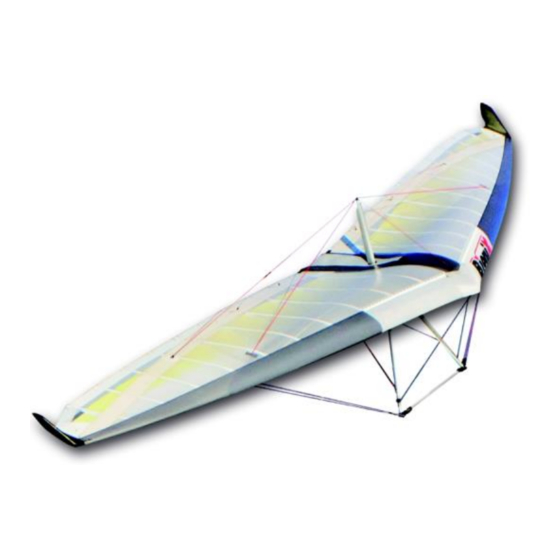
Page 6: 3-Perspective Diagram
3-Perspective Diagram Figure 3-1: BioniX in 3 Perspectives GDMUBI15-1G Version 0030... -
Page 7: Technical Specifications - Performance
Maximum Added Load / Trikes Adjustment The maximum load that may be added under the wing is 416.5 kg (918 lbs). The following chart defines the useful load of our various trike models with the BioniX 15 wing. Trike Lst Skypper... - Page 8 Caution: fitting of any equipment or any other change should never lead to exceeding the maximum empty weight value mentioned above, according to security standards and aircraft conformity. It is possible to adapt other trikes than the ones mentioned above. Their maximum weight should be less than 416.5 kg (918 lbs) fully loaded.
-
Page 9: Performance At Maximum Take-Off Weight
Performance at Maximum Take-Off Weight Trike Lst Skypper TANARG TANARG TANARG TANARG Skypper 912 (S) 912 S 912 ES 582 / S Stall speed 62 km/h 62 km/h 62 km/h 62 km/h 62 km/h 62 km/h 39 mph 39 mph 39 mph 39 mph 39 mph... -
Page 10: Instructions For Use
Instructions for Use Rigging 5.1.1 Assembly Open the wing bag, make sure that the A-frame is on top, and remove fastenings and paddings. Assemble the A-frame with the push-pin. Cables must not pass through the inside. Lift the wing from the front and rotate it so that the wing is laying with the assembled control frame flat on the ground. - Page 11 12. Carefully slide the lower sail battens in their pockets and secure them within the triangular openings. 13. Place the two straight carbon battens of the wing tips on the plastic lug attached to the tube of the leading edge, and tighten the upper surface with the clasps. 14.
-
Page 12: Disassembly
5.1.2 Disassembly Dismantling is carried out in reverse order of the assembling operations. The CORSET must imperatively be loose (set in the “slow” position) before dismantling. Before setting the wing flat on the ground, insert the protective padding on the keel over the hang point bracket and on the right A-frame strut over the guides of the fine cord of the CORSET in order to avoid damaging the sail with these jutting parts. - Page 13 Position the wing horizontally once coupled with the trike. Visually check the symmetry of the two leading edges. Check noses plates assembly, bolts, nuts, thimbles and Nicopress of the front lower longitudinal cables, swan catch correctly positioned, pushpin and wires attached. Slide your hand along the leading edges to check for possible damage.
-
Page 14: Flight Specifications
Flight Specifications 5.3.1 Operational Limitations Warning: This wing is not designed for aerobatics. It is imperative to respect the flight envelope ! Maximum Pitch attitudes 30° nose up, 30° nose down Maximum Bank angle 60° Aerobatics and deliberate spinning prohibited ... - Page 15 CORSET: The CORSET allows the pilot to adjust both the trim speed and the configuration of the wing (twist and reflex) according to speed. At low speeds, the twist increases, the reflex of the central profile decreases, thus affording better handling and the lowest stall speed. At high speeds, cruising stability is given preference, as is aerodynamic efficiency.
-
Page 16: Flight Techniques
5.3.3 Flight Techniques Taxiing: Avoid turning sharply as this generates large amounts of torque and hence wear, transmitted to the pylon, hang point and keel. Always try to keep the wing aligned with the trike when turning by bracing the control bar. Turning circle is very small, but beware –... - Page 17 and low cruise speed adjustment, it may be necessary to increase the speed before the wing is put into banking to avoid stalling the lower wing. An increase in engine power is also advised to maintain the flight level during the turn. talling: The stalling point is reached more easily with a backward hang point position.
- Page 18 Crosswind Take-off Start the take-off run with the windward wing very slightly lowered. Hold the aircraft on the ground by holding the bar slightly back from the neutral position. Keep to the axis of the runway with the front wheel control without considering efforts on the sail. Allow airspeed to build to a higher-than-normal value then rotate positively into a shallow climb attitude.
- Page 19 At height the best way to minimize pilot workload and physical fatigue is to fly the aircraft while trying to let the control bar float through turbulence. Use your arms as dampers and try not to rigidly fight the movement. Close to the ground, where accurate control is required, the displacement of the aircraft in turbulence can be reduced by bracing the control bar relative to the structure of the trike unit.
- Page 21 Appendix Wing – Quality Form Anxious to ensure the perfection of our products, we have set up a sequence of controls covering all steps of production. We are continuously working on their improvement and we are in need of your help. Please return this reply form accurately filled in if you find any issues or problems concerning your trike that could affect its quality or finish, even if it is a minor matter.
- Page 22 615 Route de l’Aérodrome, 07200 Lanas, France Telephone: +33 (0)4 75 93 66 66 • Fax: +33 (0)4 75 35 04 03 • info@aircreation.fr http://www.aircreation.fr GDMUBI15-1G Version 0030...
Need help?
Do you have a question about the BioniX 15 and is the answer not in the manual?
Questions and answers