
Related Manuals for 3DLabPrint Hawker Sea-Fury FB 11


Summary of Contents for 3DLabPrint Hawker Sea-Fury FB 11
- Page 1 Hawker Sea Fury Assembly userguide ADDIMP 3D Original Release 2 May 2020 3D Printed project by ADDIMP 3D...
- Page 2 This 3D printed project permit to reproduce the Hawker Sea-Fury FB 11. It is your responsibility to manufacture all of the parts necessary for the construction of this model. All files are provided in stl format, compatible with the majority of slicers softwares in the 3D printing market.
- Page 3 2- Parameters scale ~ 1:12 Length: 856 mm / 33 - 2/3 inch Wingspan: 974 mm / 38 - 1/3 inch Wing area : 18,1 dm² Weight of the 3D printed parts : ~750 g, Equiped weight between 1100 and 1350 g as per equipment Wing loading : 67 / 70 g/dm²...
-
Page 4: Content Of The Pack
Release 1.1 Accessories Added DYS 4215 motor mount 3- Content of the pack All the STL files, factory files (Simplify 3D) and G-codes. this version can be made in 2 or 3 axis and the wing can be fixed either by screw or by rubber band. The engine mount is installed using M3 screws + self-locking nut instead of self-tapping screws. - Page 5 Recess for balance 5- Requirements All parts are printable on a 200 x 200 x 200 mm 3D printer with 0.4 mm nozzle. Slicing software is Simplify 3D, all factory and G-codes files are provided for Ø1.75mm PLA materials. All the printed parts need less than 1kg of PLA. A profile for Simplify 3D is proposed as example in the directory ../factory (MK3PLA-3DP.fff) Setup : 3S –...
-
Page 6: Print Settings
2x Rubber band 120 x 10 mm or 1x M6 nylon screw and nut (wing fixation) Wire pushrod Ø1mm hinge sheet, thickness 0.3mm Ø2mm rod hard wood or carbon for the rudder hinges CA medium 1x Velcro strap 200 mm 2x servo extension cable for aileron, length 150 mm minimum. - Page 7 Extra restart distance (distance to begin extrusion before printing the part) = 0.05 to 0.1 mm Vertical lift (avoid collision between nozzle & part during travel moves) = 0.4mm Possible wipe option activated, may replace a part of retraction. The 3 or 4 fist layers should be at 2 outline / perimeter shells. The same for the 3 or 4 last (select outside shell first) Temperatures - Bed = 55 to 60°...
- Page 8 Elongated F1 long nose Sea-Fury-1_12-F1-long-nose Sea-Fury-1_12-F1-long-nose version Sea-Fury-1_12-F2 Sea-Fury-1_12-F2 Sea-Fury-1_12-F3 Sea-Fury-1_12-F3-W_fix Sea-Fury-1_12-F4- Sea-Fury-1_12-F4 rubber_band Sea-Fury-1_12-F5-2x Sea-Fury-1_12-F5-2x F5 (2 or 3 axis) Sea-Fury-1_12-F5-3x Sea-Fury-1_12-F5-3x F6 – 2 axis only Sea-Fury-1_12-F6 Sea-Fury-1_12-F6 Included in : Wing fixture support Sea-Fury-1_12-wing-fix Sea-Fury-1_12-F3-W_fix Battery hatch Sea-Fury-1_12-Bat- Front cover cover_Front...
- Page 9 Sea-Fury-1_12-LE-smooth-R Sea-Fury-1_12-W3L Symetrical Sea-Fury-1_12-W3-LR Sea-Fury-1_12-Aileron-L- inter Left aileron / Right Sea-Fury-1_12-Aileron-L- symetrical Sea-Fury-1_12-Aileron-LR aileron Sea-Fury-1_12-Aileron-L- exter Sea-Fury-1_12-Wing- belly_front Wing bellies (front & Updated V1.2 Sea-Fury-1_12-Wing-bellies rear) Sea-Fury-1_12-Wing- belly_rear 1_12-servo_mount_L / R Servo mount & (1+1)x2 symetrical 1_12-servos-mounts_LR cover 1_12-servo-cover_L / R Tail Horizontal stabilizer Symetrical...
- Page 10 Support pour Sea-Fury-1_12-MM-lng_35 Sea-Fury-1_12-MM-lng_35 moteur long. 35mm Support pour Sea-Fury-1_12-MM-lng_40 Sea-Fury-1_12-MM-lng_40 moteur long. 40mm Support pour Sea-Fury-1_12-MM-lng_43 Sea-Fury-1_12-MM-lng_43 moteur long. 43mm Sea-Fury-1_12-spinner- base-2_blades Spinner Ø60 mm 2 blades Sea-Fury-1_12-spinner-60 Sea-Fury-1_12-spinner- cone-2_blades Sea-Fury-1_12-spinner-big- base-2_blades Spinner Ø68 mm 2 blades Sea-Fury-1_12-spinner-68 Sea-Fury-1_12-spinner-big- cone-2_blades Landing gear (option)
- Page 11 There is a specific support to remove on W3, it is used to maintain the trailing edge during printing process. Assemble all the parts without any glue, to check the well adjustment and alignement. If you use the carbon tube option, check that it slides freely in its housing. Then glue each section together, beginning by root section, L1 with L2, then L3.
- Page 12 8.1- Leading edge (LE) with cannons or smooth As option, local leading edge on W2 are proposed as separate parts to facilitate the printing. It could be cannons or smooth. Both parts are identified Left (L) and Right (R) Parts should be glued on respectively W2R and W2L 8.2- Servo mount To facilitate the mount and setup of the servo, it is used a special mount with cover.
- Page 13 First, glue the mount to the wing. Each one have a letter to indicate the side (L for the left wing, R for right wing). You can use a servo to keep it straight. Then fit the servo on the bay, adjust the linkage to the aileron easily, once finish, screw the cover to the mount with 2 screws 2 x 10.
- Page 14 8.3- Wing bellies They are glued together, then glued on the wing. Working with the wing under the fuselage is better to help center. 3D Printed project by ADDIMP 3D...
- Page 15 9- Fuselage Assembly diagram, for details, see following pages The version with or without rudder flap is realized with sections F5 and F6. The other sections are common to both versions. • cut opening(s) for servo(s) • install elevator servo and the one for the rudder if needed •...
- Page 16 F1 – normal or long nose F5 - 2 axis F6 – (2 axis only) 3D Printed project by ADDIMP 3D...
- Page 17 F5 – 3 axis H Stabilizer Fixed rudder V stab with rudder 3D Printed project by ADDIMP 3D...
-
Page 18: Motor Mount
9.1- Motor mount The motor is installed with a specific support. It is installed from the front. The support is fixed by 3 M3 x 18 screws + self-locking nuts in the aircraft structure. There are several versions of motor supports corresponding to the main dimensions of the trade. If you wish to use another engine, do not hesitate to ask us for a special support specifying the dimensions of your engine. - Page 19 9.2- F3 preparation Glue the wing mounting bracket. The opening for the nut passage forward. The support is glued to the level of the F4 centering ribs. 9.3- Fuselage assembly (F1 to F6) First, check all the parts, remove all the residual skirt, to sand if needed the parts. Check that all sections of the tube for the elevator and rudder pushrods are well cleared and fully open along the entire length.
- Page 20 F1 with F2 are assembled together using a Ø2 mm x 6/8 mm rod ; toothpick or filament. Check the diameter of the different holes receiving these rods. If necessary, re-drill until Ø2. All other sections are centered with ribs. Place the toothpick or the pin in a hole, then cut at 2 mm height At this time, you can install the battery strap before assembly F1 with F2 F1 / F2 pins locations...
- Page 21 Assembly of other sections A peripheral rib helps with centering, check the absence of plots or wires linked to the print !!! do not bond F6 part to the fuselage until horizontal stabilizer is mount !!! You can glue each part from F1 to F5 together. Use CA with activator if needed.
- Page 22 9.4- Section F2 – F3 (rubber band or screw option) Once the whole fuselage glued (F1 to F4 at least), it is necessary to open the underside of F2 & F3 to give access for electronics. You can use cutter, electrical driller or hot cutter. Paie a special attention to the internal wing support which is very close to the cutout.
- Page 23 First, glue front & rear part, you can use Ø2 mm rod tohelp centering. Put the lock in the rear part, see below. This lock use a clip instead a spring. Then glue the lock housing under the rear cover. Take care to not glue the lock. Large access to the battery and the motor 3D Printed project by ADDIMP 3D...
- Page 24 Tails, elevator pushrods and servos Use CA glue and activator (if needed) for assembly. First, glue the horizontal stabilizer to the fuselage. Check the correct angularity between these 2 elements. Once done, glue the hinges, if using film, cut as per the cut out below and adjust on parts. ⊥...
- Page 25 Put the pushrod wire on the fuselage, Z bended extremity at the elevator side. Cut the plastic on the area below. Install the elevator on the pushrod, then glue the elevators to the hinges. 3D Printed project by ADDIMP 3D...
- Page 26 Finish with gluing F7 and the vertical stabilizer. 3D Printed project by ADDIMP 3D...
- Page 27 Option With rudder flap Remove all the supports on the fin and the rudder flap. Check the passage of the Ø2 mm hinge rod in all the parts, drill again if necessary. The length of the axle must be 128 mm +/- 1 Once the whole H-stab assembly is glued on the fuselage, glue the fin.
- Page 28 Wing fixture 11.1- With rubber band Use 120mm rubber band, attach around the printed rod With wing 3D Printed project by ADDIMP 3D...
- Page 29 11.2- With screw and nut Use M6 nylon screw and nut. If use ¼ ‘’ screw and nut, you may have to adapt le nut’s housing. First, adjust the housing for the nut, then, glue it with CA bond. Nut in the housing Receiver ans ESC Both can be installed on a specific housing in F2 3D Printed project by ADDIMP 3D...
- Page 30 Setup For aileron and elevator, use +/- 8 mm displacement, 25 to 30 % exponential. For the first flights, you can start with more exponential and / or reduced displacement. Do not forget that the manual launch involves a low speed for the first meters of flight, 3D Printed project by ADDIMP 3D...
- Page 31 Landing gear (optional) Left landing gear Assembled Exploded view Support Ø3 mm piano wire Splints + screws Ø3x10 Main gear leg Main wheel hub Main wheel tyre Main gear door Installation (Left wing shown, Right wing symetrical) 3 mm 9 mm 3D Printed project by ADDIMP 3D...
- Page 32 Tailwheel installation The use of the tool to bend the piano wire 1- Install Ø6 mm hard wood or metal pin in the holes and a Ø4 mm screw in the lower hole 3D Printed project by ADDIMP 3D...
- Page 33 2- Put the wire along the screw, tight it. 3- Bend the wire along the path on the tool 4- cut the wire at the correct length with the tool 3D Printed project by ADDIMP 3D...
- Page 34 Cut here 3D Printed project by ADDIMP 3D...
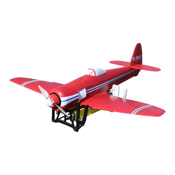
- Page 35 Stand A stand is provided as is. It help you to work around the plane and is helpful at field to support the plane fully assembled. Part Quantity File Front Sea-Fury-1_12_Stand-Front.stl Rear Sea-Fury-1_12_Stand-Rear.stl Side short Sea-Fury-1_12_Stand-Side-front.stl Side long Sea-Fury-1_12_Stand-Side-rear.stl Splint Sea-Fury-1_12_Stand-Splint.stl Front Side short...
- Page 36 Paint & markings You can find some stickers from https://callie-graphics.com/collections/hawker-sea-fury, select 1/12 scale. Many informations could be find on wikipedia. In the doc directory, you will find some stickers to print yourself on the file deco.pdf There are many web site which propose photos of the Sea Fury. Below some ideas. F-AZXJ, https://www.airliners.net/search?keywords=F-AZXJ G-CBEL,...
- Page 37 Pilots Please Attention !! - For the first flights we recommend to reduce the displacement for elevator and aileron to +/- 8mm. - Make sure the battery is well fixed in proper position. If it moves during flight it will cause the CoG move aft and can lead to uncontrollable flight behavior.
Need help?
Do you have a question about the Hawker Sea-Fury FB 11 and is the answer not in the manual?
Questions and answers