Advertisement
Quick Links
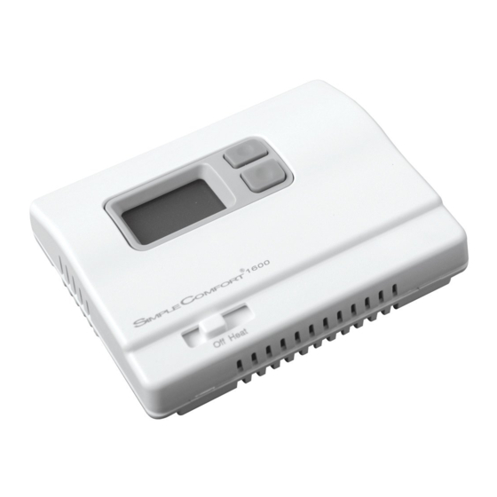
SC1600L/VL
Non-Programmable Electronic Thermostat
• Controls Single Stage Heating Systems
• Millivolt and Hydronic (water or steam) System Compatible
• Compatible with Gas and Oil Systems
• Backlit Display
• Mercury-Free,
Environmentally Safe
Installation, Operation & Application Guide
For more information on our complete range of American-made
products – plus wiring diagrams, troubleshooting tips and more,
visit us at www.icmcontrols.com
Parts Diagrams
Battery
Compartment
Specifications
Electrical rating: • Millivolt to 30 VAC/VDC
• DC Power: 3.0 VDC (2 "AA" alkaline batteries included)
• 1 amp maximum per terminal
• 2 amp maximum total load
Temperature control range: 45°F to 90°F Accuracy: ± 1°F
Back Light: Not available on N and VN models
Differential Rage: 1°F to 3°F
System configurations: 1-stage heat, gas, and oil
Terminations: R, W, S1, S2
Important Safety Information
WARNING!: Always turn off power at the main power supply before installing, cleaning,
or removing thermostat.
• This thermostat is for 24 VAC applications only; do not use on voltages over 30 VAC
• Do not short across terminals of gas valve or system control to test operation; this will damage your
thermostat and void your warranty
• All wiring must conform to local and national electrical and building codes
• Use this thermostat only as described in this manual
Package Contents/Tools Required
Package includes: SC1600 thermostat on base, thermostat cover, wiring labels, screws and wall
anchors, Installation, Operation and Application Guide.
Tools required for installation: Drill with 3/16" bit, hammer, screwdriver.
Manual Changeover
Non-Programmable
Mode
High Temp.
Freeze
Switch
Switch
Switch
The SC1600 thermostat is a digital, mercury-free, non-programmable, electronic thermostat.
Battery
• Compatible with single-stage heating systems
• Compatible as a master thermostat in zoned system applications
• Freeze Protection Feature: Protects pipes from freezing! If the room temperature drops to 40°F,
• System Customization: Choose three available temperature differential settings
ELECTRICAL SHOCK HAZARD – Turn off power at the main service panel by removing
the fuse or switching the appropriate circuit breaker to the OFF position before
removing the existing thermostat.
1. Turn off power to the heating system by removing the fuse or switching the appropriate circuit
breaker off.
2. Remove cover of old thermostat. This should expose the wires.
3. Label the existing wires with the enclosed wire labels before removing wires.
4. After labeling wires, remove wires from wire terminals.
5. Remove existing thermostat base from wall.
6. Refer to the following section for instructions on how to install this thermostat.
Replace the old labels with the enclosed
new labels.
ELECTRICAL SHOCK HAZARD – Turn off power at the main service panel by removing
the fuse or switching the appropriate circuit breaker to the OFF position before
removing the existing thermostat.
IMPORTANT: Thermostat installation must conform to local and national building and electrical
Note: Mount the thermostat about five feet above the floor. Do not mount the thermostat on
an outside wall, in direct sunlight, behind a door, or in an area affected by a vent or
duct.
1. Turn off power to the heating system by removing the fuse or switching off the appropriate circuit
breaker.
2. Move the Off/Heat switch into the Off position.
3. To remove cover, insert and twist a coin or screwdriver in the slots on the sides of the thermostat.
4. Put thermostat base against the wall where you plan to mount it (Be sure wires will feed through
the wire opening in the base of the thermostat).
5. Mark the placement of the mounting holes.
6. Set thermostat base and cover away from working area.
7. Using a 3/16" drill bit, drill holes in the places you have marked for mounting.
8. Use a hammer to tap supplied anchors in mounting holes.
9. Align thermostat base with mounting holes and feed the control wires through wire opening.
10. Use supplied screws to mount thermostat base to wall.
11. Insert stripped, labeled wires in matching wire terminals. See "Wiring Diagrams" section of this
manual.
CAUTION!: Be sure exposed portion of wires does not touch other wires.
12. Tighten screws on terminal block. Gently tug wire to be sure of proper connection. Double check
that each wire is connected to the proper terminal.
13. Insert two fresh "AA" alkaline batteries into thermostat, oriented in the direction shown on the
battery compartment.
14. Replace cover on thermostat by snapping it in place.
15. Turn on power to the system at the main service panel.
General Description
the thermostat automatically turns on the heat; the thermostat must be
in the Heat position; works even if the batteries are dead
To Remove Existing Thermostat
Replacing Wiring Labels
Old
H, W, 4
M, 4, RH, RS, R
N/A
To Install Thermostat
codes and ordinances.
New
Type
W
Heating control
R
Transformer, hot side
S1, S2
Optional remote sensor
Advertisement

Related Manuals for ICM Controls SC1600 Series


Summary of Contents for ICM Controls SC1600 Series
- Page 1 SC1600L/VL Manual Changeover General Description Non-Programmable The SC1600 thermostat is a digital, mercury-free, non-programmable, electronic thermostat. Battery Non-Programmable Electronic Thermostat • Compatible with single-stage heating systems • Compatible as a master thermostat in zoned system applications • Freeze Protection Feature: Protects pipes from freezing! If the room temperature drops to 40°F, • Controls Single Stage Heating Systems the thermostat automatically turns on the heat; the thermostat must be • Millivolt and Hydronic (water or steam) System Compatible in the Heat position; works even if the batteries are dead • Compatible with Gas and Oil Systems • System Customization: Choose three available temperature differential settings •...
- Page 2 Installing and Changing Batteries Setting the Setpoint Temperature If your LCD is blank or displaying LO BAT, the batteries are not installed or need to be changed. We 1. Place Off/Heat switch in the Heat position. suggest you change the batteries at least once a year, or whenever the LO BAT warning displays. 2. Press the down or up button a single time to see the current temperature setting. Note: After installing new batteries, you have to reset the room temperature setting and the 3. Press the down or up button until the desired temperature setpoint displays. differential setting. 4. The new temperature setpoint is automatically saved in memory. After 5 seconds, the display 1. Move the Off/Heat switch into the Off position.
Need help?
Do you have a question about the SC1600 Series and is the answer not in the manual?
Questions and answers
New batteries installed correctly but there is no display
There is no display on the ICM Controls SC1600 Series after installing new batteries because the batteries may not be installed correctly. Proper battery installation is important, and the positive ends must match the positive terminals.
This answer is automatically generated