
Subscribe to Our Youtube Channel
Related Manuals for Vertiv VRC2 Series


Summary of Contents for Vertiv VRC2 Series
- Page 1 VRC Split System VRC2 Series Rack Cooler VRC3 Series Condensing Unit User Manual Vertiv I Liebert® ™ I User Manual...
- Page 3 VRC Split System User Manual Version V1.2 Revision date Mar 18, 2020 31014128...
- Page 5 The purchased products, services and features are stipulated by the contract made between Vertiv Group Corp. and the customer. All or part of the products, services and features described in this document may not be within the purchasing scope or the usage scope. Unless otherwise specified in the contract, all statements, information recommendations in this document are provided "AS IS"...
- Page 6 Purpose of the Document This document applies to the VRC2 series and VRC3 series of cooling solutions which maintain an optimal environmental control mainly for technological ecosystems at minimal operating costs. This document gives an overview of the technical specification. The figures used in this document are for reference only. Please read this manual carefully.
- Page 7 WARNING! Risk of electric shock. Can cause equipment damage, injury or death. Open all local and remote electric power supply disconnect switches and verify with a voltmeter that power is off before working within any electric connection enclosures. Service and maintenance work must be performed only by properly trained and qualified personnel and in accordance with applicable regulations and manufacturers’...
- Page 8 Unsuitable components will impede equipment performance and may cause equipment shutdown. Therefore, Vertiv recommends the use of Vertiv OEM or Vertiv-approved components. CAUTION: Avoid touching or having skin contact with the residual gas and oils in the compressor.
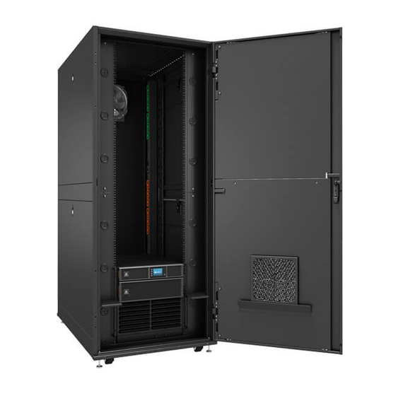
- Page 9 Preface The Vertiv VRC2 series is a split-type cooling unit which should be installed at the bottom of the rack. It is designed to be installed inside any 480 mm (19 in.) 2 or 4-post rack, including those developed by Vertiv.
-
Page 10: Table Of Contents
TABLE OF CONTENTS Table of Contents Product Overview .............................. 1 Product Introduction ......................... 1 Model Description ..........................2 Model Nomenclature ........................2 Components ............................3 Technical Specifications ........................5 Pre-Installation..............................10 Fittings ............................. 10 Self-Prepared Materials ........................10 Transportation and Movement ....................... 11 Unpacking ............................ - Page 11 Indoor Unit Maintenance ........................ 51 Condensing Unit Maintenance ......................52 Electrical Connection Maintenance ....................53 Cooling System Maintenance ......................54 Leakage Detection (F-gas) ....................... 54 System Diagnosis Testing ......................... 55 Maintenance Inspection Checklist ....................56 Troubleshooting ............................... 57 Troubleshooting..........................57 Fan Troubleshooting ........................
- Page 12 PART I GENERAL INFORMATION Vertiv I VRC Split System I User Manual...
-
Page 13: Product Overview
Product Overview The Vertiv™ - VRC2 series and VRC3 series are split-type cooling units for utilization in the rack which does not permit any access to any unauthorized and unqualified personnel. If the rack is placed in shopping malls, light industry, or any business environment, it must be used only by professionally trained personnel. -
Page 14: Model Description
2 = 230V, 1 Ph, 50/60 Hz 0 = Standard Unit 5 = Low Ambient Unit 2 = Split System Indoor Unit 3 = Split System Condensing Unit VRC=Vertiv Rack Cooler Figure 1-3 Nomenclature Vertiv I VRC Split System I User Manual... -
Page 15: Components
Indoor and the Condensing unit as shown below. 1.4.1 Indoor Unit The components of the indoor unit are depicted in Figure 1-4. Suction Pressure Indoor fan evaporator temp transducer Vertiv I VRC Split System I User Manual... - Page 16 1.4.2 Condensing Unit The components of the condensing unit are depicted in Figure 1-5 and Figure 1-6. Condenser coil Inverter rotary Condenser fan compressor Figure 1-5 Standard condensing unit internal parts Vertiv I VRC Split System I User Manual...
-
Page 17: Technical Specifications
This module ensures that the air conditioner system can work at -34 °C (-29.2 °F). 1.5 Technical Specifications The detailed technical specifications which include the mechanical and the electrical details are mentioned in Table 1-2. Vertiv I VRC Split System I User Manual... - Page 18 21 °C (69.8 °F). • When the VRC unit is used in a closed rack, the heat load should be evenly placed in rack and unused rack position should be covered with blanking plates. Vertiv I VRC Split System I User Manual...
- Page 19 40 °C Maximum Capacity, kW (85 °F) (95 °F) (104 °F) 29.4 °C 85 °F) Evaporator Air Temperature to 35 °C Cooling Module 95 °F) (Return Air Control) 40 °C 104 °F) Vertiv I VRC Split System I User Manual...
- Page 20 (104 °F) 29.4 °C 0.91 0.89 0.87 (85 °F) Evaporator Air Temperature to 35 °C Cooling Module 0.93 0.91 0.89 (95 °F) (Return Air Control) 40 °C 0.95 0.93 0.91 (104 °F) Vertiv I VRC Split System I User Manual...
- Page 21 PART II INSTALLATION Vertiv I VRC Split System I User Manual...
-
Page 22: Pre-Installation
The cables routed from the room to the unit and the circuit breakers must be prepared at the customer site or are to be obtained by the customer; the specifications for the same are given in the Table 2-2. Vertiv I VRC Split System I User Manual... -
Page 23: Transportation And Movement
Table 2-3, Figure 2-2 and Figure 2-3 show the dimensions of the units component with the package. Forklift Direction Figure 2-2 Package dimensions – indoor unit Vertiv I VRC Split System I User Manual... - Page 24 If a hand pallet truck or an electric forklift truck is used, the tines of the hand pallet or electric forklift must be aligned with the center of gravity to prevent the package from toppling or falling over as depicted in Figure 2-5. Vertiv I VRC Split System I User Manual...
-
Page 25: Unpacking
Remove the packing materials, including paper cover, support cardboard, paper box, cushion • and paper corner in a specific order as mentioned from the top side of the unit. Remove the unit from the wooden pallet. • Vertiv I VRC Split System I User Manual... - Page 26 Remove the packing materials, including paper cover, support cardboard, paper box, cushion • and paper corner in a specific order as mentioned from the top side of the unit. Remove the unit from the wooden pallet. • Vertiv I VRC Split System I User Manual...
-
Page 27: Equipment Installation Room Requirements
NOTES: Avoid locating the indoor unit in concave or narrow areas which can affect the airflow. It is prohibited • to use the cooling unit in an unconducive condensing environment. Vertiv I VRC Split System I User Manual... -
Page 28: Environment
The indoor unit is a specifically engineered air conditioning unit. It is recommended to install the indoor unit inside the rack at the lowest rack unit space, as shown in the installation section. Vertiv I VRC Split System I User Manual... -
Page 29: Clearance Space
(17.72 in.) from any wall, obstacles or adjacent devices. It is a must to provide these clearance distances as shown in Figure 2-10 and Figure 2-11 to ensure appropriate airflow across the condensing unit. Wall Back Front 450mm [17.72''] 450mm [17.72''] 200mm [7.87''] 450mm [17.72''] Vertiv I VRC Split System I User Manual... -
Page 30: Weight Bearing Capacity
If any parts or components are missing or damaged, immediately report to the carrier about the • same. If hidden damages are observed, then contact the local offices of that carrier as well as Vertiv Group Corp. at the earliest. Vertiv I VRC Split System I User Manual... -
Page 31: Mechanical Installation
3.2 System Installation Layout The overall layout of the unit which comprises of both the indoor unit and the condensing unit is depicted in Figure 3-2, Figure 3-3 and Figure 3-4. Figure 3-2 Indoor unit Vertiv I VRC Split System I User Manual... - Page 32 Table 3-2. Table 3-2 The dimension of the air deflector Range of Dimensions (Unit: mm (in.)) Component VRC300 Standard Condensing VRC301 Unit (19.68) (22.17) (9.17) VRC302 Vertiv I VRC Split System I User Manual...
-
Page 33: Installing The Unit
M5x12 T20. Torque=4.0 Nm (2.95 ft.-lb.). Once in place, tighten the nuts on the front rail part studs. Torque = 5.6 Nm (4.13 ft.-lb.). Vertiv I VRC Split System I User Manual... - Page 34 The physical appearance of the condensing unit is shown in Figure 3-3 and Figure 3-4. The top view of the standard condensing unit is shown in Figure 3-9 and the low ambient condensing unit is shown in Figure 3-10. Vertiv I VRC Split System I User Manual...
- Page 35 This trap will retain refrigerant oil in the off cycle of the compressor. When the compressor starts, oil in the trap will be carried up the vertical riser and return to the compressor immediately. Vertiv I VRC Split System I User Manual...
- Page 36 Drain pipe of condensate Heat insulation Gas side pipe Floor material water (extend to outdoor to drain condensate water) 1:200 Outdoor unit Figure 3-12 The Condensing unit is installed lower than the indoor unit Vertiv I VRC Split System I User Manual...
- Page 37 50 mm (1.97 in.) higher than the ground and 50 mm (1.97 in.) wider than the condensing unit base. The condensing is around 44 kg (97 lbs.); therefore, utmost care must be taken while removing it; any • mishandling will result in severe injury and damage to the equipment. Vertiv I VRC Split System I User Manual...
- Page 38 Make sure the sealing block is installed tightly. Drain Fitting Sealing Block Drain Fitting Figure 3-14 Installing the drain fitting Vertiv I VRC Split System I User Manual...
- Page 39 6. Fix the pump bracket part 1 with tightening the 4 screws in Figure 3-17. 7.Install pump bracket part 2 to pump bracket part 1 with tightening the 2 screws in Figure 3-19. Vertiv I VRC Split System I User Manual...
-
Page 40: Connecting The Copper Pipes To The Unit
(only when the pipeline is long). The standard refrigerant of the unit is R410A. The charging amount for low ambient condensing unit is 4.0kg (8.82 lbs), while other units is 1.3 kg (2.87 lbs). Vertiv I VRC Split System I User Manual... - Page 41 If an extended piping kit is required or if the equivalent length exceeds 20 m (65.62 ft.), it’s necessary to add a check valve at the liquid pipe outlet of the condensing unit. Also, consult your local Vertiv Sales Office, if the vertical distance between the indoor unit and condensing unit exceeds 15 m (49.21 ft.).
- Page 42 (0.82) (2.46) (6.90) (6.23) The procedure for fitting the connectors of the condensing unit are mentioned in Figure 3-26. The same can be replicated for fitting the connectors of the indoor unit. Vertiv I VRC Split System I User Manual...
- Page 43 When installing the condensing unit 7.5m higher than the indoor unit, a trap should be installed on the discharge pipe. This trap will retain refrigerant oil in the off cycle of the compressor. Vertiv I VRC Split System I User Manual...
-
Page 44: Refrigerant Charge
If there is no leakage observed, vacuum the unit at the needle valves. Add refrigerant to air conditioner after evacuation. For standard unit, position of needle valves for vacuuming and charging the refrigerant is shown Figure 3-27. Vertiv I VRC Split System I User Manual... - Page 45 Figure 3-28 Vacuuming and charging for low ambient condensing unit If it is necessary to add more refrigerant and refrigerant oil, please contact Vertiv for technical assistance. For the exact amount of refrigerant and refrigerant oil to be charged in the system, refer to Table 3-8 and Table 3-9.
-
Page 46: Installation/Pre- Commissioning Check List
The condensate pump and pipes are connected properly All pipe joints are firmly fixed All pipe connectors and fasteners are tightly fastened. After all these items are checked and confirmed, continue with the electrical installation works of the unit. Vertiv I VRC Split System I User Manual... -
Page 47: Electrical Installation
Use correctly sized copper wire only and verify that all electrical connections are tight before turning power On. Check all electrical connections periodically and tighten as necessary. Vertiv I VRC Split System I User Manual... -
Page 48: Cable Connection
VRC202 230 Vac 50/60 Hz VRC302 230 Vac 50/60 Hz 0.37 VRC350 208/230 Vac 60 Hz 0.13 0.87 VRC351 208/230 Vac 60 Hz 0.08 0.37 VRC352 230 Vac 50/60 Hz 0.08 0.37 Vertiv I VRC Split System I User Manual... - Page 49 Terminal block for LLSV Power for Input Power and Outdoor Fan Power Grounding Grounding screw 1 screw 2 Cable clamp 1 Cable clamp 2 Cable clamp 3 Figure 4-4 Input Cabling connections – Indoor Power terminal Vertiv I VRC Split System I User Manual...
- Page 50 Inner cable hole Compressor communication Terminal block for line Outdoor Fan Power Grounding Grounding screw1 screw2 External cable hole Cable Cable Cable clamp1 clamp2 clamp3 Figure 4-6 Standard condensing unit electric connection illustration Vertiv I VRC Split System I User Manual...
-
Page 51: Communication Cable Connecting
Network port Network port RS485-1 RS485-2 Outdoor Communication RS485-3 Display plug Input Power Terminal block Outdoor fan Terminal block LLSV Block Figure 4-8 Display, power and monitoring cable connections in the indoor unit Vertiv I VRC Split System I User Manual... -
Page 52: Installation Inspection
After confirming the above points, you can start the commissioning of the unit. NOTES: • Do not power on the unit until any Vertiv authorized technical personnel has checked and confirmed the unit. Vertiv I VRC Split System I User Manual... -
Page 53: Controller Operation Instructions
5.2 Control Buttons The micro-processing controller provides five control buttons, as shown in below Figure 5-2. ON/ OFF Button Up Arrow Button ENT Button Down Arrow Button ESC Button Figure 5-2 Control Buttons Vertiv I VRC Split System I User Manual... -
Page 54: On Screen
(off, running, standby locked). The icons on the main screen indicate the unit output status, unit property unit operating status. The icons and their definitions are displayed in the Table 5-2. Vertiv I VRC Split System I User Manual... -
Page 55: Unit Working Icons
The specific alarm information includes XX/YY, alarm type alarm generation time, as shown in Figure 5-5. XX indicates the alarm SN YY indicates the total number of reported alarms. Vertiv I VRC Split System I User Manual... - Page 56 Figure 5-8 Items of alarm handle attribute menu Temp Set Select Main Menu -> Temp set enter the screen as shown in Figure 5-9 the Temperature Setting values will be permanently saved. Vertiv I VRC Split System I User Manual...
- Page 57 You can query the operation time of the device on this menu, as shown in Figure 5-11. 23 h Comp Figure 5-11 Run time menu Help Menu The menu includes Date &Time information. You can view the relevant information, as shown in Figure 5-12. Vertiv I VRC Split System I User Manual...
- Page 58 Date (Y) 2018 Time(M) <Date&Time> Date (M) Time(S) Date (D) Time (H) Figure 5-12 Date & Time menu Vertiv I VRC Split System I User Manual...
- Page 59 PART III SYSTEM OPERATION & GENERAL MAINTENANCE Vertiv I VRC Split System I User Manual...
-
Page 60: Startup Commissioning
The indoor and condensing units have been charged with the rated amount of refrigerant in factory, when the indoor unit and condensing unit have been connected as an entire system at sites, the steps mentioned below should be followed to ensure the normal operation of the unit: Vertiv I VRC Split System I User Manual... -
Page 61: Commissioning Complete Inspection
Check that the temperature settings are correct and are controlled within range Are there any abnormal alarms or warnings displayed on the controller? Make sure all the other functions are set correctly. Vertiv I VRC Split System I User Manual... -
Page 62: System Operation And Maintenance
Unsuitable components will impede equipment performance and may cause equipment shutdown. Therefore, Vertiv recommends the use of Vertiv OEM or Vertiv-approved components. 7.2 Electrical Inspection Inspect the control board and temperature sensor every 6 months for loose electrical connections and circuit corrosion. -
Page 63: Indoor Unit Maintenance
Inspect the drain pipe for normal operation. Ensure no pipe buckling is present. If the pipe buckling happens, the new pipe should be used. Ensure that reservoir, pump filter and inlet tube are free of sludge and debris. If not, please clean it. Pump brackets Pump Pump reservoir Vertiv I VRC Split System I User Manual... -
Page 64: Condensing Unit Maintenance
24 hours every day continuously, any unusual airflow obstruction must be cleared in time to avoid the damage to the cooling system and other system components caused by reduced air volume. Vertiv I VRC Split System I User Manual... -
Page 65: Electrical Connection Maintenance
NTC electronic expansion valve control board. Check whether the contact and connection of the fan power cable, signal cable rotating speed feedback signal cable are firmly fixed. Vertiv I VRC Split System I User Manual... -
Page 66: Cooling System Maintenance
Figure 7-6. Check detection area (front) and detection area (rear) from the front and rear of the VRC202 unit, respectively. 4. Restore the VRC202 unit to its original state after the check is completed. Vertiv I VRC Split System I User Manual... -
Page 67: System Diagnosis Testing
7.8 System Diagnosis Testing The microprocessor controller supports the manual mode and provides diagnostic functions such as manually enabling and disabling parts. Such functions can be used to detect states of the system functional parts. Vertiv I VRC Split System I User Manual... -
Page 68: Maintenance Inspection Checklist
Check whether the cables and meter reading of each sensor are within prescribed range. Check whether the wiring and coil of the electronic expansion valve control board are loose EEV electric Check electrical connections board Check the surface for signs of corrosion Vertiv I VRC Split System I User Manual... -
Page 69: Troubleshooting
Use other dehumidifier to control the air Severe The air humidity is too high humidity condensation or water leakage EEV adjusts abnormally Check if the EEV coil or EEV cable is loose Vertiv I VRC Split System I User Manual... -
Page 70: Fan Troubleshooting
Check whether the communication cable between the electronic is faulty. expansion valve control board and the main control board is properly connected. Vertiv I VRC Split System I User Manual... -
Page 71: Fault Diagnosis And Handling Of The Air Conditioning System
Check whether the fan is faulty. Table 8-1 describes the decrease The fan is faulty. diagnosis and handling methods. Check the surface of the micro-channel evaporator and Blockage of the evaporator periodically handle the blockage problem. Vertiv I VRC Split System I User Manual... -
Page 73: Appendix I: System Diagram (Standard Unit)
Electronic Expansion Valve Distributor Evaporator Service Suction Temperature Valve Sensor Low Pressure Gas Line Gas Quick Transducer Connector Service Valve Liquid Line High Pressure Liquid Quick Transducer Connector Interconnecting Piping Indoor Unit Vertiv I VRC Split System I User Manual... -
Page 74: Appendix Ii: System Diagram (Low Ambient Unit)
Electronic Expansion Valve Trap Distributor Evaporator Service Suction Temperature Valve Sensor Low Pressure Gas Line Gas Quick Connector Transducer Service Valve Liquid Line High Pressure Liquid Quick Connector Transducer Interconnecting Piping Indoor Unit Vertiv I VRC Split System I User Manual... -
Page 75: Appendix Iii: Wiring Diagram (Vrc200/Vrc201 Unit)
Compressor EARTH GROUND EARTH GROUND Communication CONNECTION CONNECTION CONNECTION PANEL RDU-C RDU-C Compressor MBV Outdoor Fan Communication LINE VOLTAGE RDU-SIC 1 PHASE SUPPLY Display SEE UNIT NAMEPLATE FOR MAIN SUPPLY WIRE SIZING Vertiv I VRC Split System I User Manual... -
Page 76: Appendix Iv:wiring Diagram (Vrc300/Vrc301 Unit)
LINE VOLTAGE Compressor 1 PHASE SUPPLY Outdoor Fan Communication Compressor EARTH GROUND EARTH GROUND CONNECTION CONNECTION Communication CONNECTION PANEL CON1 EMI Filter Outdoor Capacitor High Pressure TEMP. Switch Switch Compressor Inverter Inductor Compressor Vertiv I VRC Split System I User Manual... -
Page 77: Appendix V:wiring Diagram (Vrc350/Vrc351 Unit)
1 PHASE SUPPLY Communication Compressor EARTH GROUND EARTH GROUND CONNECTION CONNECTION Communication CONNECTION PANEL Low Pressure Switch RHTR CON1 EMI Filter Outdoor Capacitor LLSV High Pressure TEMP. Switch Switch Compressor Inverter Inductor Compressor Vertiv I VRC Split System I User Manual... -
Page 78: Appendix Vi:wiring Diagram (Vrc202 Unit)
Compressor EARTH GROUND EARTH GROUND Communication CONNECTION CONNECTION CONNECTION PANEL RDU-C RDU-C Compressor LLSV Outdoor Fan LINE VOLTAGE Communication RDU-SIC 1 PHASE SUPPLY Display SEE UNIT NAMEPLATE FOR MAIN SUPPLY WIRE SIZING Vertiv I VRC Split System I User Manual... -
Page 79: Appendix Vii:wiring Diagram (Vrc302 Unit)
Compressor Outdoor Fan 1 PHASE SUPPLY Communication Compressor EARTH GROUND EARTH GROUND Communication CONNECTION CONNECTION CONNECTION PANEL CON1 EMI Filter Outdoor Capacitor High Pressure TEMP. Switch Switch Compressor Inverter Inductor Inductor Compressor Vertiv I VRC Split System I User Manual... -
Page 80: Appendix Viii:wiring Diagram (Vrc352 Unit)
1 PHASE SUPPLY Communication Compressor EARTH GROUND EARTH GROUND CONNECTION CONNECTION Communication CONNECTION PANEL Low Pressure Switch RHTR CON1 EMI Filter Outdoor Capacitor LLSV High Pressure TEMP. Switch Switch Compressor Inverter Inductor Inductor Compressor Vertiv I VRC Split System I User Manual... -
Page 81: Suppliers Declaration Of Conformity
Suppliers Declaration of Conformity Unique Identifier: VRC200, VRC201, VRC300, VRC301, VRC350, VRC351 Party Issuing Supplier’s Declaration of Conformity Vertiv Group Corp. 1050 Dearborn Drive Columbus, OH 43085 Customer service hotline: 614-888-0246 FCC Compliance Statement (for products subject to Part 15) This device complies with part 15 of the FCC Rules. - Page 83 Vertiv.com I 1-4/F, 6-10F, Block B2, Nanshan I Park, No.1001 Xueyuan Road, Nanshan District, 518055 Shenzhen, Guangdong, CHINA © 2019 Vertiv Group Corp. All rights reserved. Vertiv and the Vertiv logo are trademarks or registered trademarks of Vertiv Group Corp. All other names and logos referred to are trade names, trademarks or registered trademarks of their respective owners.
Need help?
Do you have a question about the VRC2 Series and is the answer not in the manual?
Questions and answers