
Related Manuals for Milnor E-P Express


Summary of Contents for Milnor E-P Express
- Page 1 Manual Number: MCCXBB01 Edition (ECN): 2020184 Controller Reference The E-P Express ® Controller PELLERIN MILNOR CORPORATION Post Office Box 400, Kenner, Louisiana 70063–0400, U.S.A.
-
Page 3: Table Of Contents
2.3 Programming the E-P Express Control .................20 2.3.1 How to Avoid Data Loss ..................21 2.3.2 How to Return to Run Mode (Option 0) ...............21 2.3.3 How to Add or Change a Formula ................22 2.3.3.1 Quick Reference for E-P Express ® Programming........22 Pellerin Milnor Corporation... - Page 4 Controller..................32 2.3.5 Restoring the Standard Formulas ................33 2.3.5.1 Chart 1: Restore Standard Formulas (Part A)..........34 2.3.5.2 Part B ......................35 2.3.5.3 Part C ......................35 2.3.5.4 Restoring the Standard Formulas on Models Employing the Milnor ® E-P Plus ® and E-P Express ®...
- Page 5 3.2 How to Use and Erase the Formula Counter ..............47 4 Testing and Troubleshooting .......................49 4.1 Error Messages .......................49 4.1.1 Error Messages at Power Up .................49 4.1.2 Error Messages during Normal Operation ............50 4.2 The E-P Express ® Manual Menu ..................51 4.2.1 The Manual Menu....................51 4.2.1.1 Components....................51 4.2.1.2 How to Access the Manual Menu ............52...
- Page 6 Outputs ....................55 Table 10 Interpretation of Test DIP Switch Display ...............57 Table 11 DIP Switch Positions for E-P Plus ® and E-P Express ® Machines (External transmit button required) ..................63 Table 12 External Serial Link Pin Assignments ..............64 Table 13 Milnor Printer Cables ....................67...
-
Page 7: Preface
This manual has the best data that was available when your machine was made. If you cannot find the necessary data: • Are you looking for data about a component not made by Milnor ® but used on your ma- chine—for example, a motor or a brake caliper? We usually do not put the instructions of... -
Page 8: Table 1 Trademarks
Table 1. Trademarks AutoSpot™ ® ® GreenFlex™ MilMetrix PulseFlow ® GreenTurn™ MilTouch™ Ram Command™ Drynet™ Hydro-cushion™ MilTouch-EX™ RecircONE ® E-P Express ® Mentor ® MILRAIL™ RinSave ® E-P OneTouch ® Mildata ® Miltrac™ SmoothCoil™ ® ® PBW™ ® E-P Plus... -
Page 9: Commissioning
Make a check of the data: • when commissioning the machine • when required by error message • after replacing the microprocessor board • after upgrading the software • after adding or removing optional equipment Make the necessary changes. Pellerin Milnor Corporation... -
Page 10: Steps That Are Necessary When You Change Data
Vital Information About the Forces Imparted to Sup- porting Structures by Laundering Machines BNUUUI01.C01 0000189336 A.5 C.3 1/2/20 2:14 PM Released This document replaces Milnor ® document BIWUUI02. All laundering machines impart static and dynamic forces to the supporting structures (foundation and soil, floor, and building). -
Page 11: Disclaimer Of Responsibility
Commissioning 1.2.1 Disclaimer of Responsibility BNUUUI01.C02 0000189359 A.5 C.3 B.3 1/2/20 2:14 PM Released Pellerin Milnor Corporation accepts no responsibility for damage or loss as a result of: • inadequate supporting structures • interference with the use of the facility caused by machine operation The facility owner/operator is solely responsible to ensure that: •... -
Page 12: Primary Information Sources
NOTICE: All data is subject to change without notice and may have changed since last printed. It is the responsibility of the potential owner/operator to obtain written confirma- tion that any data furnished by Milnor ® applies for the model number(s) and serial num- ber(s) of the purchased machine(s). -
Page 13: Prevent Damage From Chemical Supplies And Chemical Systems
The company that does these procedures must make sure that these procedures do not cause dam- age. Pellerin Milnor Corporation accepts no responsibility for chemical damage to the ma- chines it makes or to the goods in a machine. -
Page 14: Figure 2 Incorrect Configurations That Let The Chemical Supply Go In The Ma
Figure 2. Incorrect Configurations That Let the Chemical Supply Go In the Machine by a Siphon Schematic Views Legend P... Pump T... Chemical tank S... The siphon occurs above here. Liquid in the gray parts of the chemical tube and tank can go in the machine. Pellerin Milnor Corporation... -
Page 15: Equipment And Procedures That Can Prevent Damage
— There is a manifold on the machine to at- tach chemical tubes from a chemical pump system. The manifold has a source of water to flush the chemical supplies with water. Figure 4. Examples of Manifolds for Chemical Tubes. Your equipment can look different. Pellerin Milnor Corporation... -
Page 16: Close The Line
WARNING: Electric Shock Hazard — Contact with high voltage electricity will kill or seriously injure you. Even when the machine is not running, three-phase power and control circuit power are still present at several locations within the cabinet and at some electrical components. Pellerin Milnor Corporation... -
Page 17: Maximizing Chemical Injection Precision
Increasing the programmed injection time makes any variation less significant. Use pumps and/or valves sized to allow inject times of at least 10 seconds. If injection times for a specific chemical vary widely from one formula to another, consider using two pumps or valves for Pellerin Milnor Corporation... -
Page 18: Pump Signal Connections
1.5.2 Pump Signal Connections BNCOUI02.C01 0000206324 A.5 A.6 A.3 1/2/20 1:25 PM Released The E-P Express ® controller closes certain relay contacts when chemicals are desired and to flush the chemical system after each injection. These signals are alternating current at the control cir- cuit voltage and cannot be made potential-free. -
Page 19: Timer Stop Connections
For timer stop to operate, the chemical system should include a normally open contact between these two connectors. When the contact is open, the machine runs normally. When the contact is closed, the machine timer stops until the contact opens again. Pellerin Milnor Corporation... - Page 20 Commissioning Figure 7. Timer Stop Connections Legend Inside of Rear Console (T_E shown, others similar) A... Timer stop connections B... Processor board C... Inverter` Pellerin Milnor Corporation...
-
Page 21: Programming
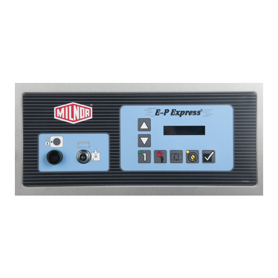
2 Programming BNCJHP05 / 2018445 BNCJHP05 0000206320 1/2/20 1:16 PM Released Controls on E-P Express ® Washer-extractors BNCJHP05.C01 0000206318 A.5 B.3 A.3 1/2/20 1:16 PM Released The controls on these Milnor ® washer-extractors include push-buttons, some of which include in- dicator lights. - Page 22 (with ), the light goes off when any coast time expires and the door is un- locked. If the formula runs to completion, the light goes off when the coast time following the final extract step expires. Pellerin Milnor Corporation...
-
Page 23: Control Functions During Manual Operation
) to delete or insert a step in a wash formula, respectively. 2. The Terminate button ( ) returns the user to the main programming menu (top line of dis- play reads “Program X Menu”) from the Add/Change Formula and the Standard Formulas Pellerin Milnor Corporation... -
Page 24: Selecting An Industry Formula Set
DIP switches on the processor board to change the machine configuration for a differ- ent operation. This document describes how to set the DIP switches. A different operation name- plate is necessary on some models. Get operation nameplates from your dealer or the Milnor ®... - Page 25 Do not assume that the switch is right side up. Always reference the la- � bels (OFF, ON, 1, 2, etc.) printed on the switch when setting DIP switches. Figure 9. Location of DIP Switches Processor Board Legend DIP switch Board identification area DIP Switch (Partial View) Pellerin Milnor Corporation...
-
Page 26: Programming The E-P Express ® Control
BNCXUP12 / 2018465 BNCXUP12 0000206669 1/2/20 1:35 PM Released Programming the E-P Express ® Control BNCXUP12.C01 0000206668 A.5 D.3 C.3 1/2/20 1:35 PM Released The microprocessor controller used in this washer extractor operates in three modes, depending on whether the machine is being used to process goods (the Run mode or Formula menu) or is being programmed with operating characteristics to be used when a wash formula is started (the Program mode) or being tested (the Manual or Test mode). -
Page 27: How To Avoid Data Loss
This is Option 0 of the Program menu. From this display, return PROGRAM MENU OK TURN KEY TO RUN to the Formula menu or select another available menu option. Returns to Run mode (Formula menu) Scrolls the available choices in the Program menu. Pellerin Milnor Corporation... -
Page 28: How To Add Or Change A Formula
. The control system will inform the person programming the machine whether the selected formula has already been programmed. 2.3.3.1 Quick Reference for E-P Express ® Programming BNCXUP12.T01 0000206804 A.5 D.3 A.7 1/2/20 1:35 PM Released This part of this document briefly describes how to program a wash formula. For a more detailed... -
Page 29: Moving Through The Operations And Decisions
00 (end formula) until you change it to another valid type of step. 2.3.3.3 How to Create a New Formula BNCXUP12.C06 0000208359 A.5 D.3 A.4 1/2/20 1:35 PM Released Creating a new formula with the E-P Express ® controller entails adding and defining steps in one of the blank formula slots. -
Page 30: How To Delete A Formula
BNCXUP12.C12 0000208539 A.5 D.3 A.4 1/2/20 1:35 PM Released Display or Action Explanation Deletes the selected step. The next step becomes the current step by assuming the number of the step that was just deleted. All fol- lowing steps move one number lower. Pellerin Milnor Corporation... -
Page 31: How To Save Changes
(hot, cold, or split). Any chemicals may be injected. The step timer begins counting when high level is achieved and continues for the programmed amount of time. When the step time expires, the controller commands the motor to turn the Pellerin Milnor Corporation... -
Page 32: Flush (Tt=04, 05, Or 06)
(hot, cold, or split). Any chemicals may be injected, although this is not common. For any flush operation on the E-P Express ® controller, the step timer begins counting when high level is achieved and continues for the programmed time. -
Page 33: Rinse (Tt=10, 11, Or 12)
In machines with the E-P Express® controller, rinse steps are always performed at high water level and the programmed temperature. This controller also allows the injection of any desired chemicals dur- ing rinse operations. -
Page 34: Finish (Tt=13)
The timer causes the current step to end when the programmed time elapses. Time is programmed in minutes, mi- nutes, and quarter-minutes, with a maximum programmable time for each step of 633 (63 minutes and 45 seconds). Pellerin Milnor Corporation... -
Page 35: C = Chemicals
Typical programming display for chemical injection. F12 TT MMQ 00000 S03 06 081 The E-P Express ® controller provides five separate injection signals and one manifold flush sig- nal. Consult the person responsible for connecting the chemical supply system to the machine (usually the chemical supplier) for information on which chemical is connected to each signal. -
Page 36: How To Configure The Controller
These values are always reset to 30 seconds whenever the standard formulas are restored, as described Section 2.3.5 : Restoring the Standard Formulas, page 33 Accepts the displayed selection. Accepts the displayed selection and reverts to the previous config- ure decision. Pellerin Milnor Corporation... -
Page 37: The Configure Decisions
Factory testing has found that a drain time of 60 seconds provides � some margin of safety for a machine that drains freely into an open trough. Increase drain time if the machine drains into an enclosed pipe, especially if that same pipe might simultaneously drain additional machines. Pellerin Milnor Corporation... -
Page 38: About Chemical Injection With The E-P Express
30 seconds. By default, Chem 1 inject time for each formula is 30 seconds until changed. The minimum value is 1 sec- ond; the maximum value is 255 seconds (4:15). 2.3.4.2.1 About Chemical Injection with the E-P Express ® Controller BNCXUP12.C28 0000208873 A.5 D.3 A.6 1/2/20 1:35 PM Released The normal duration for all chemical injection signals from this controller is 30 seconds. -
Page 39: Restoring The Standard Formulas
This selection replaces formulas 1 through 10 with the standard industry formulas and removes all data from formulas 11 through 30. 2. Option 1 replaces only formulas 1 through 10 with the standard industry formulas. This leaves any user-programmed data in formulas 11 through 30 intact. Pellerin Milnor Corporation... -
Page 40: Chart 1: Restore Standard Formulas (Part A)
The controller will pause for a few seconds while the standard formulas are written to the con- troller memory. 8. Return to Run mode When the display becomes active again, turn the Run/Program keyswitch to the Run position. Pellerin Milnor Corporation... -
Page 41: Part B
2.3.5.4 Restoring the Standard Formulas on Models Employing the ® ® ® Milnor E-P Plus and E-P Express Controller BNCJUP02.T03 0000191347 A.5 D.3 B.3 1/2/20 1:16 PM Released Display or Action Explanation PROGRAM MENU This is Option 0 of the Program menu. From this display, either OK TURN KEY TO RUN return to Run mode or select another menu item. -
Page 42: Data Transfer (Option 4)
® Certain Milnor controllers described in this manual can transfer memory between the machine and a Milnor serial memory storage device or between two machines. Refer to Table 7: Control- lers Capable of Transferring Memory, page 36 to determine the hardware and software require- ments for memory transfer. - Page 43 Transferring Memory, page 36 with the specified software installed. • The Milnor part number for the processor board appears on a white sticker near the Milnor logo on the processor board. • The revision level of the processor board is white lettering stamped directly on the green cir- cuit board, located below the part number sticker.
-
Page 44: Establishing The Required Connections
Clear Memory and returning it to the normal position. When the Ready light comes on again (after about 45 seconds), the storage device is ready to accept data from the machine controller. Pellerin Milnor Corporation... -
Page 45: Saving Data From The Machine To The Storage Device Or A Second Machine
DATA TRANSFER1 The machine controller is set as the Master device, making the MASTER storage device the slave. Pellerin Milnor Corporation... - Page 46 Explanation Acknowledges that the data transfer is complete and returns to the Program menu. PROGRAM MENU Data Transfer menu display. Scroll to Program menu item 0, DATA TRANSFER then turn the Run/Program keyswitch to the Run position. Pellerin Milnor Corporation...
-
Page 47: Restoring Saved Data To The Machine From The Storage Device Or Another Machine
The machine controller is set as the Slave device, making the stor- DATA TRANSFER0 SLAVE age device the Master. The Master device always controls when the data transfer starts and sends the data to the slave device. If Pellerin Milnor Corporation... - Page 48 Return to normal operating mode. Press if necessary to con- firm that the key is at Run. RUN PROGRAM00 OK TO The Run Program display appears to indicate that it is safe to POWER OFF turn the machine off. Pellerin Milnor Corporation...
- Page 49 Programming Turn off power to the machine(s). Disconnect the memory storage device, remove the key, and put both in secure locations. Pellerin Milnor Corporation...
-
Page 50: Operating
® ® Milnor washer extractors with E-P Express controls do not use a speed sensing device to verify that the basket has stopped rotating. Therefore, when power is first applied to the machine, at least 80 seconds must elapse before any further operations can be attempted. This provides suffi- cient time for the basket to coast to a complete stop if power was lost while the machine was in high speed extract and restored before the basket stopped. -
Page 51: Selecting A Formula
BNCJHO03.C07 0000208865 A.5 A.4 A.3 1/2/20 1:16 PM Released Display or Action Explanation 23:04 F02S01 02:37 These two displays alternate during normal operation while any L=A1/D1 Hot Wash chemical injection signal is enabled. The number on the right end Pellerin Milnor Corporation... -
Page 52: How To Shorten, Terminate, Or Suspend A Running Formula
3.1.6 How to Restart after Power Loss BNCJHO03.C09 0000209064 A.5 A.4 A.3 1/2/20 1:16 PM Released The E-P Express ® control remembers the formula and step it was executing if power fails or if the wall disconnect is turned off while the machine is operating in automatic mode. -
Page 53: How The Flush Valve Works
BNCJHO03.C10 0000209063 A.5 A.4 A.3 1/2/20 1:16 PM Released ® The E-P Express controller provides an output signal that activates the flush valve for 20 to 30 seconds 15 seconds after the last chemical injection for each bath ends. If a bath is shortened or terminated before or while this valve is energized, the flush valve will be turned off. - Page 54 Operating Shows the count in the top right corner of the display. RUN FORMULA This machine cleaned 38 cycles with formula 05. 05 FORMULA NUMBER 05 Sets the count in the formula counter equal to 0. Pellerin Milnor Corporation...
-
Page 55: Testing And Troubleshooting
E-P Express ® Control, page 20 2. Reinstall the standard (default) formulas according to the default formula loading procedure Section 2.3 : Programming the E-P Express ® Control, page 20 3. Reprogram any lost wash formulas according to Section 2.3 : Programming the E-P Express... -
Page 56: Error Messages During Normal Operation
E-P Express ® Control, page 20 5. Reinstall the standard (default) formulas according to the default formula loading procedure Section 2.3 : Programming the E-P Express ® Control, page 20 6. Reprogram lost wash formulas according to Section 2.3 : Programming the E-P Express ®... -
Page 57: The E-P Express ® Manual Menu
BNCXUT01 / 2018454 BNCXUT01 0000210242 1/2/20 1:35 PM Released The E-P Express ® Manual Menu BNCXUT01.C01 0000210738 A.5 A.7 A.3 1/2/20 1:35 PM Released 4.2.1 The Manual Menu BNCJHT01.C02 0000190167 A.5 A.7 A.9 1/2/20 1:16 PM Released 4.2.1.1... -
Page 58: How To Access The Manual Menu
Manual menu was accessed appears on the display. 4.2.1.3 How to Return to the Run Mode from the Manual Menu BNCJHT01.R02 0000190749 A.5 A.7 A.9 1/2/20 1:16 PM Released Display or Action Explanation Enters the Manual menu from Run mode. Pellerin Milnor Corporation... -
Page 59: Determining The Software Version
SOFTWARE DATE CODE Hold both buttons depressed to view the software date code and machine configuration information, as shown below. Machine style (/T = T_X), software date code (21001), and con- E-P EXPRESS/T 21001 HEALTHCARE LAUNDRY figuration (Healthcare Laundry). RUN FORMULA... -
Page 60: Actuating Microprocessor Outputs
Testing and Troubleshooting Table 8. E-P Express ® Inputs Display Code Input Name Connector-Pin Door closed M6–1 Low Water Level M6–9 Vibration switch tripped M6–2 Input from Inverter M6–10 High water level M6–3 Keyswitch in Program position M6–11 not used M6–4... - Page 61 0=OFF 1=ON Disables the output if it was enabled, then returns to the Run mode. RUN FORMULA Display of Run mode. OK TO POWER OFF Table 9. E-P Express ® Outputs Output Page- Description Consequences of Actuation Number Column...
-
Page 62: Testing And Verifying The Dip Switch Settings
Testing and Troubleshooting Table 9 E-P Express ® Outputs (cont'd.) Output Page- Description Consequences of Actuation Number Column Device Distribution (drain) speed Locks door and turns cylinder at drain 1–i 3–20/3–17 (Door must be closed) speed. Clockwise wash speed Locks door and turns cylinder clock- 1–j... -
Page 63: Viewing Inputs And Outputs During Operation
This is a typical display while the machine is running a formula. L=A1/D1 Hot Wash displays the inputs. A plus sign (+) indicates the input is grounded, while a minus sign (–) indicates the input is not grounded. Pellerin Milnor Corporation... -
Page 64: Table 9 E-P Express ® Outputs
Testing and Troubleshooting ABCDEFGHIJK typical display of input status while the machine is running. Refer +++-------- Table 9: E-P Express ® Outputs, page 55 to determine which in- put is represented by each character on the display. displays the first 11 outputs (Page 0). A plus sign (+) indicates the output is actuated, while a minus sign (–) indicates the output is... -
Page 65: Supplemental Information
Milnor ® washer-extractors. Along with certain external electromechanical relay logic and sensing ® devices, they control all machine and system functions. Not every Milnor microprocessor sys- tem includes all the following components. 5.1.1 Keyswitches BNCJUF01.C02 0000190132 A.5 C.3 A.6 1/2/20 1:16 PM Released... -
Page 66: Cpu Processor Board
Depending on the processor board, output relays may be either socket-mounted to a separate out- put board, or permanently soldered to the processor board. H_J, F_J, V_J, and X_J models, as well as all E-P Express ® models, use the 188 processor board with soldered relays. The SPST (single pole, single throw) relays have the same load parameters as those used in other models (25VA). -
Page 67: Option Outputs (E-P Plus ® Models Only)
BNUUUP01.C01 0000196602 A.5 A.4 1/2/20 2:14 PM Released A serial memory storage device similar to one shown below can be used to store machine config- uration and formula data for most current models of Milnor ® machines. DIP switches inside the storage device allow you to configure the device to accept data from several different machine types and software versions. - Page 68 Supplemental Information Figure 12. Serial Memory Storage Device Figure 13. Rear View of Circuit Board Legend View 1... DIP switch 2... Software chip 3... Location of Transmit button, if equipped 4... Key switch Pellerin Milnor Corporation...
-
Page 69: Construction Of External Serial Link Cables
NOTE: The currently approved printers and printer configuration settings are provided Section 5.4 : Printer Requirements and Settings, page 67 . A pre-assembled machine- to-printer cable similar to the cable described here, is available from Milnor (P/N 10YMK2PNTR). Pellerin Milnor Corporation... -
Page 70: Pin Identification
DIN receptacle (which uses male pins) and the mating plug (which uses female pin sockets), each viewed from the wire entry side. The receptacle is normally installed and wired at the Milnor factory. The plug and female pin sockets for customer use are provided in a bag inside the electric box. -
Page 71: How To Wire The Cables
BNCUUP02.C04 0000196981 A.5 A.9 A.8 1/2/20 1:30 PM Released Multi-conductor shielded cable that meets the following minimum requirements must be used in the applications covered herein. Conforming cable may be purchased from Milnor (P/N 09V300A04S) or purchased from another source: •... -
Page 72: Connecting A Machine To A Serial Memory Storage Device
Connecting a Machine to a Serial Memory Storage Device BNCUUP02.C06 0000197240 A.5 A.9 1/2/20 1:30 PM Released The cable used with the serial memory storage device (download box) available from Milnor, see related note in Section 5.3 : Construction of External Serial Link Cables, page 63 , is permanently attached to the storage device. -
Page 73: Printer Requirements And Settings
Released Printer Requirements and Settings BNCUUI01.C01 0000196632 A.5 A.6 1/2/20 1:30 PM Released NOTICE: Because of the many differences among printer makes and models, Milnor ® cannot ensure suitability or troubleshoot printers other than those described in this docu- ment (or certain older approved models), with the required interface cable. -
Page 74: Configuring The Citizen Gsx-190 Printer
Configuring the Epson LX300 Printer BNCUUI01.R03 0000196629 A.5 A.6 1/2/20 1:30 PM Released The Epson model LX300 printer was supplied by Milnor prior to March 2001 to print data from microprocessor controllers with printing functions. When shipped from Milnor, this printer was configured to operate correctly with Milnor equipment. -
Page 75: Previous Printer Models
Previous Printer Models BNCUUI01.C02 0000196628 A.5 A.6 1/2/20 1:30 PM Released The Epson LX300 printer replaced the Epson LX-810, which replaced the Epson LX-800. For in- formation on these older printer models, request document MSSM0251AE from the Milnor factory. Pellerin Milnor Corporation...
Need help?
Do you have a question about the E-P Express and is the answer not in the manual?
Questions and answers
Machine won't spin
The Milnor E-P Express machine may not spin due to the following reasons identified in the context:
1. Inverter Fault: If the microprocessor does not receive an input from the inverter within 14 seconds of starting a formula, the basket remains stationary.
2. Vibration Switch Activated: If the vibration switch closes, the machine stops the spinning operation and initiates a recovery sequence.
3. Power Application Delay: When power is first applied to the machine, at least 80 seconds must elapse before further operations can be attempted to allow the basket to stop completely if it was in high-speed extract mode during a power loss.
To resolve these issues, follow the recovery steps specified in the manual, such as pressing the appropriate recovery keys, ensuring proper input signals, or waiting for the required time.
This answer is automatically generated