Table of Contents
Advertisement
Quick Links
Advertisement
Table of Contents

Subscribe to Our Youtube Channel
Related Manuals for Mitsubishi MELSEC-FX0N Series


Summary of Contents for Mitsubishi MELSEC-FX0N Series
- Page 1 USER’S MANUAL -32NT-DP Profibus-DP Interface Unit...
- Page 2 FX0N-32NT-DP Profibus-DP InterfaceUnit Foreword • This manual contains text, diagrams and explanations which will guide the reader in the correct installation and operation of the FX -32NT-DP Profibus-DP Interface Unit. It should be read and understood before attempting to install or use the unit. •...
- Page 3 This manual confers no industrial property rights or any rights of any other kind, nor does it confer any patent licenses. Mitsubishi Electric Corporation cannot be held responsible for any problems involving industrial property rights which may occur as a result of using the contents noted in this manual.
- Page 4 FX0N-32NT-DP Profibus-DP Interface Unit...
- Page 5 FX0N-32NT-DP Profibus-DP Interface Unit Guidelines for the Safety of the User and Protection of the FX -32NT-DP Profibus-DP Interface Unit. This manual provides information for the use of the FX -32NT-DP Profibus-DP Interface Unit. The manual has been written to be used by trained and competent personnel. The definition of such a person or persons is as follows: a) Any engineer who is responsible for the planning, design and construction of automatic equipment using the product associated with this manual, should be of a competent...
- Page 6 FX0N-32NT-DP Profibus-DP Interface Unit Note’s on the Symbols Used in this Manual At various times through out this manual certain symbols will be used to highlight points of information which are intended to ensure the users personal safety and protect the integrity of equipment.
- Page 7 FX0N-32NT-DP Profibus-DP Interface Unit • Under no circumstances will Mitsubishi Electric be liable or responsible for any consequential damage that may arise as a result of the installation or use of this equipment. • All examples and diagrams shown in this manual are intended only as an aid to understanding the text, not to guarantee operation.
- Page 8 FX0N-32NT-DP Profibus-DP Interface Unit...
-
Page 9: Table Of Contents
FX0N-32NT-DP Profibus-DP Interface Unit Table of Contents Guideline ..................... iii 1. Introduction....................1-1 1.1 Features of the 32NT-DP ..................1-1 1.2 External Dimensions.................... 1-2 1.2.1 Pin Configuration of Profibus-DP Connector ............. 1-4 1.3 System Configuration ..................1-5 1.4 Applicable PLC ....................1-6 2. - Page 10 FX0N-32NT-DP Profibus-DP Interface Unit 4. Buffer Memories (BFMs) Allocation............4-1 4.1 Buffer Memories (BFM) Lists ................4-2 4.2 Received Output Data, Input Data to Send (BFM #0 ~ #19) <Read/Write> ..4-3 4.3 Data Exchange Status Bit (BFM #20) <Read Only> ........... 4-4 4.4 Swap Byte Order (BFM #21) <Read/Write>...
- Page 11 FX0N-32NT-DP Profibus-DP Interface Unit 5. Setting Operation ..................5-1 5.1 Installing 32NT-DP Parameters in the DP-master ..........5-1 5.1.1 DP-slave Address Setting in the DP-master.............. 5-1 5.1.2 Setting the Number and Format of Input and Output Words in the DP-master ..5-2 5.2 Setting Slave Address in the 32NT-DP ...............
- Page 12 FX0N-32NT-DP Profibus-DP Interface Unit...
-
Page 13: Introduction
FX0N-32NT-DP Profibus-DP Interface Unit Introduction 1 Introduction This FX -32NT-DP Profibus-DP Interface Unit (called “32NT-DP” hereinafter) can be used as a slave module to connect an FX , FX , FX series programmable controllers 2N or (called “PLC” hereinafter) to an existing Profibus-DP network. The 32NT-DP provides an intelligent slave function for decentralized control applications which need to exchange data with Profibus-DP master CPUs (called “DP-master”... -
Page 14: External Dimensions
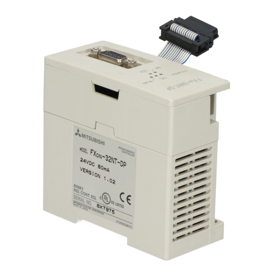
FX0N-32NT-DP Profibus-DP Interface Unit Introduction 1 External Dimensions Accessories: GSD Files (FD 1 piece) MASS (Weight): Approx.0.3 kg(0.66lbs) Dimensions: mm (inches) Figure 1.1: External Dimensions 4 ( 0 . 1 6 " ) - 3 2 N T - D P P O W E R R U N D I A... - Page 15 FX0N-32NT-DP Profibus-DP Interface Unit Introduction 1 a) Profibus-DP connector (9-pin D-SUB: #4-40 inc. inch screw thread) b) FG terminal (screws terminal: M3.5 (0.14")) c) Power supply terminals (screws terminal: M3.5 (0.14")) d) Extension cable e) BF LED f) POWER LED g) DC LED h) RUN LED i) DIA LED...
-
Page 16: Pin Configuration Of Profibus-Dp Connector
FX0N-32NT-DP Profibus-DP Interface Unit Introduction 1 1.2.1 Pin Configuration of Profibus-DP Connector The connector is a 9-pin D-SUB (#4-40 inc. inch screw thread) type, and the pin configuration is shown below. Figure 1.2: Pin Layout of Profibus-DP Connector Table 1.1: Profibus-DP Connector Pin Configuration Pin No. -
Page 17: System Configuration
FX0N-32NT-DP Profibus-DP Interface Unit Introduction 1 System Configuration Figure 1.3: System Configuration DP-master Profibus-DP network Slave or Slave or master master -32NT-DP *1 The units at each end of the Profibus-DP network must have a terminating resistor. This will either be in the master or slave unit or in the DP connector. *2 PLC is FX , FX , FX... -
Page 18: Applicable Plc
FX0N-32NT-DP Profibus-DP Interface Unit Introduction 1 Applicable PLC For setting up a system, the 32NT-DP can be connected directly to the PLC’s extension port or to any other extension unit’s right side extension port. The 32NT-DP occupies 8 points of I/O on the PLC’s expansion bus. The 8 points can be allocated from either inputs or outputs. -
Page 19: Wiring And Mounting
FX0N-32NT-DP Profibus-DP Interface Unit Wiring and Mounting 2 Wiring and Mounting Caution 1) Do not lay signal cable near to high voltage power cable or house them in the same trunking duct. Effects of noise or surge induction may occur. Keep signal cables a safe distance of more than 100 mm (3.94") from these power cables. -
Page 20: Mounting
FX0N-32NT-DP Profibus-DP Interface Unit Wiring and Mounting 2 Mounting 2.1.1 Arrangements The 32NT-DP connects on the right side of the connected FX , FX , FX or FX series main unit or extension unit/block (including special function blocks). For further information of mounting arrangements, refer to the hardware manual of the connected main unit. - Page 21 FX0N-32NT-DP Profibus-DP Interface Unit Wiring and Mounting 2 Figure 2.2: Attach to DIN Rail and Remove from DIN Rail „ ƒ ‚ 2) Direct mounting to back walls The 32NT-DP can be mounted with the M4 screw by using the direct mounting hole. However, an interval space between each unit of 1 2 mm is necessary.
-
Page 22: Wiring
FX0N-32NT-DP Profibus-DP Interface Unit Wiring and Mounting 2 Wiring 2.2.1 EC and EMC Conformity Using FX For compliance to EC and EMC regulations it is necessary to fit a ferrite noise filter to the AC power lines of the FX main unit or extension unit from which the 32NT-DP 24V power should be taken. -
Page 23: Power Supply Wiring
FX0N-32NT-DP Profibus-DP Interface Unit Wiring and Mounting 2 2.2.2 Power Supply Wiring 1) When connecting a 32NT-DP to an AC power supply type PLC of the FX , FX or FX Series, the 24V required by the 32NT-DP needs to be supplied from the FX , FX or FX Series PLC. - Page 24 FX0N-32NT-DP Profibus-DP Interface Unit Wiring and Mounting 2 2) When connecting a 32NT-DP to a DC power supply type PLC of the FX , FX , FX Series, the 24V required by the 32NT-DP needs to be supplied from external power supply same as supplied to the PLC.
-
Page 25: Profibus-Dp Wiring
FX0N-32NT-DP Profibus-DP Interface Unit Wiring and Mounting 2 2.2.3 Profibus-DP Wiring To connect the 32NT-DP to a Profibus-DP network use only the Profibus connectors and shielded twisted-pair cable complying with EN50170. For Profibus connectors see the Profibus connector manual. Figure 2.5: Wiring DC power supply type PLC: Supply from the external power supply. -
Page 26: Terminating Resistor
FX0N-32NT-DP Profibus-DP Interface Unit Wiring and Mounting 2 Figure 2.6: Profibus Connector Shielded twisted-pair cable to Profibus-DP network -32NT-DP Profibus-DP Interface Unit 2.2.4 Terminating Resistor The units at each end of the Profibus-DP network must have a terminating resistor. This will either be in the master or slave unit or in the Profibus connector. -
Page 27: Specifications
FX0N-32NT-DP Profibus-DP Interface Unit Specifications 3 Specifications General Specifications Table 3.1: General Specifications Item Specifications General specifications Same as those for connecting PLC (excluding withstand voltage) Withstand voltage 500V AC for 1 minute (between terminals and earth) Power Supply Specifications Table 3.2: Power Supply Specifications Item Specifications... -
Page 28: Performance Specifications
FX0N-32NT-DP Profibus-DP Interface Unit Specifications 3 Performance Specifications Table 3.3: Performance Specifications Item Specifications 20 words can be sent and received during one bus cycle (default value 16 words). Transmission data The number of transmitted words can be changed between 4 and 20 words. 9.6k, 19.2k, 45.45k, 93.75kbps 1,200m 187.5kbps... -
Page 29: Buffer Memories (Bfms) Allocation
FX0N-32NT-DP Profibus-DP Interface Unit Buffer Memories (BFMs) Allocation 4 Buffer Memories (BFMs) Allocation Caution: 1) Do not access the buffer memory defined as “Not used” (BFM #31) by FROM/TO instruction. There is a possibility to cause abnormal operation of the 32NT-DP if accessing these buffer memories. -
Page 30: Buffer Memories (Bfm) Lists
FX0N-32NT-DP Profibus-DP Interface Unit Buffer Memories (BFMs) Allocation 4 Buffer Memories (BFM) Lists Table 4.1: Buffer Memories Lists Description BFM No. Read (FROM instruction) Write (TO instruction) BFM #0 ~ #19 Received output data (see section 4.2.) Input data to send (see section 4.2.) BFM #20 Data exchange status bit (see section 4.3.) <Read only>... -
Page 31: Received Output Data, Input Data To Send (Bfm #0 ~ #19)
FX0N-32NT-DP Profibus-DP Interface Unit Buffer Memories (BFMs) Allocation 4 Received Output Data, Input Data to Send (BFM #0 ~ #19) <Read/Write> When the 32NT-DP is in data exchange mode, the received data from a DP-master is read by the PLC using a FROM instruction. Data is written to the 32NT-DP and sent to the DP-master using a TO instruction. -
Page 32: Data Exchange Status Bit (Bfm #20)
FX0N-32NT-DP Profibus-DP Interface Unit Buffer Memories (BFMs) Allocation 4 Data Exchange Status Bit (BFM #20) <Read Only> BFM #20 contains a status bit for data exchange. If this value is “1", the module is in data exchange mode and the received data is valid. If this value is “0", the module is not in data exchange mode. -
Page 33: Baud Rate (Bfm #24)
FX0N-32NT-DP Profibus-DP Interface Unit Buffer Memories (BFMs) Allocation 4 Baud Rate (BFM #24) <Read Only> BFM #24 shows the current baud rate of the DP network. The baud rate depends on the DP-master settings. The following table shows the supported baud rates and the value of BFM #24. -
Page 34: Communication Status (Bfm #25)
FX0N-32NT-DP Profibus-DP Interface Unit Buffer Memories (BFMs) Allocation 4 Communication Status (BFM #25) <Read Only> BFM #25 is the 32NT-DP’s communication status. According to the status of the 32NT-DP the bits are set and reset as follows. Table 4.3: Communication Status (BFM #25) Bit No. - Page 35 FX0N-32NT-DP Profibus-DP Interface Unit Buffer Memories (BFMs) Allocation 4 Table 4.3: Communication Status (BFM #25) Bit No. Description 1 (ON) 0 (OFF) UNFREEZE global No UNFREEZE command Bit 10 UNFREEZE command received control received Bit 11 FREEZE global control FREEZE command received No FREEZE command received Bit 12 UNSYNC global control UNSYNC command received...
-
Page 36: Global Control Command
FX0N-32NT-DP Profibus-DP Interface Unit Buffer Memories (BFMs) Allocation 4 4.7.1 Global Control Command The global control commands are processed by the 32NT-DP itself and require no specific measures from the programmable controller user program. 1) Clear data global control When this command is received, the 32NT-DP clears the output data. 2) UNFREEZE global control The UNFREEZE command stops freeze control mode. -
Page 37: Profibus Module Id (Bfm #26)
FX0N-32NT-DP Profibus-DP Interface Unit Buffer Memories (BFMs) Allocation 4 PROFIBUS Module ID (BFM #26) <Read Only> This buffer memory contains the Profibus module ID number for the 32NT-DP. The ID number is “F032H”. Slave Address (BFM #27) <Read/Write> The 32NT-DP supports setting of the DP-slave address by a Profibus-DP class 2 master via the network and by PLC via a TO instruction. -
Page 38: User Diagnostics (Bfm #28)
FX0N-32NT-DP Profibus-DP Interface Unit Buffer Memories (BFMs) Allocation 4 4.10 User Diagnostics (BFM #28) <Read/Write> By writing to BFM #28 the user can transmit high priority diagnostic data to the DP-master. Data from BFM #28 is transmitted as external diagnostic data to the DP-master where it can be used in the master application. -
Page 39: Error Status (Bfm #29) (Read Only)
FX0N-32NT-DP Profibus-DP Interface Unit Buffer Memories (BFMs) Allocation 4 4.11 Error Status (BFM #29) (Read Only) BFM #29 indicates error status of the 32NT-DP. Table 4.5: Error Status (BFM #29) Bit No. Description 1 (ON) 0 (OFF) Bit 0 General error This bit is ON if b2 ~ b4 are ON No general error Bit 1 Not used... -
Page 40: General Error (Bfm #29 Bit 0)
FX0N-32NT-DP Profibus-DP Interface Unit Buffer Memories (BFMs) Allocation 4 4.11.1 General Error (BFM #29 Bit 0) When a general error occurs (bit 0 = ON) the 32NT-DP tries to send the data of BFM #28 and #29 as a static diagnosis message to the DP-master. In this case data can not be exchanged with the DP-master. -
Page 41: From/To Watchdog Timer (Bfm #29 Bit 7)
FX0N-32NT-DP Profibus-DP Interface Unit Buffer Memories (BFMs) Allocation 4 4.11.5 FROM/TO Watchdog Timer (BFM #29 Bit 7) If no communication requests (FROM / TO) are received by the 32NT-DP within a 1 second time period a watch dog timer error occurs and bit 7 is set ON. If bit 7 is ON, an external diagnosis message will be sent to the DP-master. -
Page 42: Model Identification Code (Bfm #30)
FX0N-32NT-DP Profibus-DP Interface Unit Buffer Memories (BFMs) Allocation 4 4.12 Model identification code (BFM #30) <read only> The identification number for a 32NT-DP is read by using the FROM instruction. The identification number for the 32NT-DP is K7020. By reading this identification number, the user may create built-in checking routines to check whether the physical position of the 32NT-DP matches to that of the software. -
Page 43: Setting Operation
FX0N-32NT-DP Profibus-DP Interface Unit Setting Operation 5 Setting Operation For details how to set-up a DP-master please refer to the appropriate DP-master manuals. Installing 32NT-DP Parameters in the DP-master To be able to exchange data with a DP-master the 32NT-DP must receive a valid parameter and configuration data message from the DP-master. -
Page 44: Setting The Number And Format Of Input And Output Words In The Dp-Master
FX0N-32NT-DP Profibus-DP Interface Unit Setting Operation 5 5.1.2 Setting the Number and Format of Input and Output Words in the DP-master The 32NT-DP supports only word data format and word consistency. Combinations of 2 modules and 4 modules can be configured. The configurations shown in the following table are possible. -
Page 45: Setting Slave Address In The 32Nt-Dp
FX0N-32NT-DP Profibus-DP Interface Unit Setting Operation 5 Setting Slave Address in the 32NT-DP When setting the DP-slave address from the PLC follow the example program. Example program The following is an example of how to set the slave address to “10” of a 32NT-DP connected as block No.0. - Page 46 FX0N-32NT-DP Profibus-DP Interface Unit Setting Operation 5 MEMO...
-
Page 47: Example Program
FX0N-32NT-DP Profibus-DP Interface Unit Example Program 6 Example Program The following is an example program. Figure 6.1: Example Program M8002 Normal byte order FNC 79 Error-1 Send diagnosis to DP-master Note: Error-2 If no FROM / TO instructions are sent to the 32NT-DP an error will be signaled in the DP-master... - Page 48 FX0N-32NT-DP Profibus-DP Interface Unit Example Program 6 Figure 6.1: Example Program 24V DC power error 24V DC power error flag Y001 Hardware error Hardware error flag Y002 EEPROM error EEPROM error flag Y003 Configuration error Configuration error flag Y004 Parameter error Parameter error flag Y005 Slave address change error...
- Page 49 FX0N-32NT-DP Profibus-DP Interface Unit Example Program 6 Figure 6.1: Example Program M8000 Check 32NT-DP in data exchange FNC 78 mode. When 32NT-DP is in data FROM exchange mode, M41 is turned ON. FNC 10 X000 When X000 is ON and 32NT-DP is in FNC 78 FROM data exchange mode, the PLC reads...
- Page 50 FX0N-32NT-DP Profibus-DP Interface Unit Example Program 6 MEMO...
-
Page 51: Diagnostics
FX0N-32NT-DP Profibus-DP Interface Unit Diagnostics 7 Diagnostics Preliminary Checks 1) Check POWER and DC LED. If this is OFF, please see section 7.2. 2) Check that the slave address is the same at the 32NT-DP (BFM #27) and the setting value of the Profibus-DP master configuration tool. -
Page 52: Led Check
FX0N-32NT-DP Profibus-DP Interface Unit Diagnostics 7 LED Check Check the status of the LED’s for the 32NT-DP as follows. 1) DC LED check Table 7.1: DC LED Check Status Description 32NT-DP is OK, 24V DC power source is OK. Otherwise Possible 24V DC power failure, if OK then possible 32NT-DP failure. -
Page 53: Check Bfm #29 Error Status Of The 32Nt-Dp
FX0N-32NT-DP Profibus-DP Interface Unit Diagnostics 7 3) RUN, BF and DIA LED check : ON : OFF Table 7.3: RUN, BF and DIA LED Check RUN LED BF LED DIA LED Status Action Normal operation No communication/baud search mode Point a) External diagnostic error Point b) Static diagnostic error... - Page 54 FX0N-32NT-DP Profibus-DP Interface Unit Diagnostics 7 MEMO...
-
Page 55: Further Information Manual List
FX0N-32NT-DP Profibus-DP Interface Unit Appendix A Appendix A: Further Information Manual List Table A-1: Further Information Manual List Manual name Manual No. Description Series PLC Describes FX Series PLC specification details for JY992D66301 Hardware Manual I/O, wiring, installation and maintenance. (DSS/DS) Series PLC Describes FX (DSS/DS) Series PLC specification... - Page 56 FX0N-32NT-DP Profibus-DP Interface Unit MEMO...
- Page 58 USER’S MANUAL -32NT-DP Profibus-DP Interface Unit HEAD OFFICE: TOKYO BUILDING, 2-7-3 MARUNOUCHI, CHIYODA-KU, TOKYO 100-8310, JAPAN HIMEJI WORKS: 840, CHIYODA CHO, HIMEJI, JAPAN Effective Mar. 2008 JY992D61401E Specification are subject (MEE) to change without notice.
Need help?
Do you have a question about the MELSEC-FX0N Series and is the answer not in the manual?
Questions and answers