
Subscribe to Our Youtube Channel
Related Manuals for Teleste ACcess Series


Summary of Contents for Teleste ACcess Series
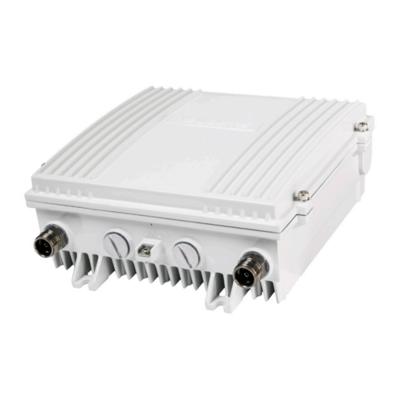
- Page 1 User manual AC1500 59300547 Rev.001 21.4.2016 1(16) ACcess Series User Manual Teleste Corporation AC1500 Broadband amplifier...
-
Page 2: Table Of Contents
User manual AC1500 59300547 Rev.001 21.4.2016 2(16) Contents Introduction ......................2 Installation ......................3 Housing ........................ 3 Interfaces ......................4 Powering ......................5 Front panel ......................6 Features ......................7 Diplex, input and output modules, return path module ........7 Setup ........................ -
Page 3: Installation
User manual AC1500 59300547 Rev.001 21.4.2016 3(16) Installation Housing The AC1500 amplifier should be installed vertically so that the external cable connectors and ventilation hole are pointing downward. Secure the housing with the three mounting brackets. Figure 1 depicts for the positions of mounting brackets as well as other installation dimensions. -
Page 4: Interfaces
User manual AC1500 59300547 Rev.001 21.4.2016 4(16) Interfaces 8616013 Grounding point Input port Output port 1 Input bypass / Output port 3 Output port 2 Figure 2. Port locations – bottom view The AC1500 amplifier has four dedicated cable connection points: input, input bypass/output and two outputs. -
Page 5: Powering
User manual AC1500 59300547 Rev.001 21.4.2016 5(16) Powering NOTE! To reduce the risk of electric shock, do not remove the shielding cover of the power supply unit if it is connected. All electrical installations must be carried out by authorized and competent technicians in accordance with the national or regional electrical regulations. -
Page 6: Front Panel
User manual AC1500 59300547 Rev.001 21.4.2016 6(16) Front panel 8615015 Figure 4. AC1500 front panel 1) Input centre conductor seizure screw 13) Output module 1 (see table 2) 2) Input module (see table 1) 14) Output 1 centre conductor seizure screw 3) Input test point 15) Output module 2 (see table 3) 4) Input diplex filter... -
Page 7: Features
User manual AC1500 59300547 Rev.001 21.4.2016 7(16) Features Diplex, input and output modules, return path module The AC1500 amplifier is delivered according to the specifications defined in the ordering code. Optional return path operation needs plug-in diplex filters (Figure 4, positions 4 and 10). The available diplex filter types are CXF065 (65/85 MHz), CXF085 (85/105 MHz) and CXF204 (204/258 MHz). -
Page 8: Setup
User manual AC1500 59300547 Rev.001 21.4.2016 8(16) passive return path module. Options for the return path module (Figure 4 pos. 20) are AC6250 (65 MHz), AC6251 (85 MHz) and AC6252 (204 MHz). Setup Preparation Check installed plug-in modules in the amplifier. Note! Amplifier does not work if one of these components is missing. -
Page 9: Options For Level And Slope Control
User manual AC1500 59300547 Rev.001 21.4.2016 9(16) The return path requires a specific signal level for proper operation. The ideal level at the amplifier is based on the incoming power and the maximum loss through which that signal must travel on its way to the amplifier. A typical individual channel level at the return path input is in range of •... -
Page 10: Installation
6) Up / Down / Enter buttons Indicators The two led indicators on the front panel are labelled as "Status" and "ALSC" (in AC6158 only). During the power-up sequence both leds will be yellow and "Teleste" text scrolls through the display. Status led Description green Operation OK, locked to RIS carrier ██████████... -
Page 11: User Interface
11(16) User interface During the power-up sequence "Teleste" text scrolls through AC6158 display. If there is no button activity during ~3 minutes, the display will go dark. Pressing any button wakes up the display and activates the first menu item. -
Page 12: Manual Gain And Slope Control
User manual AC1500 59300547 Rev.001 21.4.2016 12(16) Manual gain and slope control AC1500 and AC2500 amplifiers' electrical interstage gain and slope controls can be manually adjusted in -5…+5 dB range with 0.5 dB steps. The values are stored in the amplifier memory, default is 0 dB. Note that adjustment values above ±4 dB may not be always achieved, depending on unit, temperature and selected cabling type. -
Page 13: Remote Ingress Switching
21.4.2016 13(16) Remote ingress switching Teleste RIS (Remote Ingress Switching) system allows low cost ingress detection and countermeasures at headend. It consists of a head-end HDM155 RIS controller module which communicates with RIS receiver modules such as AC6158 installed in the field equipment using one-way forward path RF link. -
Page 14: Legal Declarations
This document is protected by copyright laws. Unauthorized distribution or reproduction of this document is strictly prohibited. Teleste reserves the right to make changes to any of the products described in this document without notice and all specifications are subject to change without notice. - Page 15 Notes...
- Page 16 www.teleste.com...
Need help?
Do you have a question about the ACcess Series and is the answer not in the manual?
Questions and answers