Advertisement
Quick Links
Broadband Cable Networks
A: AC1000 AMPLIFIER PLATFORM
General
The AC1000 is a single active output amplifier with
high gain. The amplifier can be used for distribution
purpose at high gain mode and also as a line
amplifier with lower gain. It is extremely versatile
and scalable through a wide range of plug-in
options. The amplifier platform can also be easily
upgraded to operate as a fibre node. The part A of
this document is devoted to procedures possible
while the Access platform is used as an amplifier.
Similar information concerning the fibre node will be
found in part B of this document respectively.
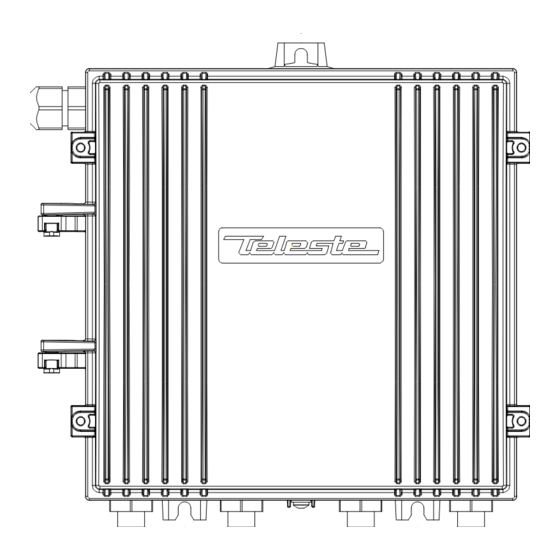
Installation
The AC1000 can be installed either into a street
cabinet or to an outdoor environment. The node
should be installed in a vertical position so that the
external cable connectors are underneath. Secure
the housing with three mounting brackets – see
fig.1 for the positions of mounting brackets as well
as other installation dimensions.
The cover opens with the hinges to the left. The
open cover can be removed by first opening the
cover into a 90 degrees angle and the lifting it off
the hinges. Close the lid by tightening the four
retaining bolts in a diagonal sequence. Before
closing the lid check that
nothing is trapped between the lid and the case
-
-
all case gaskets are in their correct positions
A sufficient tightening torque is 3 Nm. Ensure that
the lid seats evenly on the rubber gasket. The class
of enclosure is IP54.
To ground the amplifier housing connect at least
2
4 mm
grounding wire (Cu) from a proper earth to
the grounding point (see the arrow in fig.1).
Cable connections
Underneath the AC1000 amplifier there are four
cable connection points: input, input bypass/output
and two outputs. The amount and function of the
actual
connectors
configuration. All coaxial outputs have a standard
PG11 thread and they accept
adapter or connector. A suitable length of the cable
inner conductor exposed for the connectors is
approximately 20 mm (fig.2).
varies
with
the
chosen
any KDC type
User Manual
59300001
December 17, 2002
8602013
Fig.1. Dimensions of the AC1000
housing and the grounding point
location
Type
Description
AC6110
0 dB input module
AC6112
1/12 dB tap
AC6120
0 dB output module
AC6124
two-way splitter
AC6128
2/9 dB tap
AC6111
termination module
Table 1. List of available input and
output connector modules
ac1000_rf
Fig.2. RF cable connector
AC1000
Rev.003
1(11)
printed on December 17, 2002
Advertisement

Subscribe to Our Youtube Channel
Related Manuals for Teleste AC1000


Summary of Contents for Teleste AC1000
-
Page 1: Cable Connections
A: AC1000 AMPLIFIER PLATFORM 8602013 General The AC1000 is a single active output amplifier with high gain. The amplifier can be used for distribution purpose at high gain mode and also as a line amplifier with lower gain. It is extremely versatile and scalable through a wide range of plug-in options. -
Page 2: Power Feed
External power can also be fed through the amplifier into the network. Maximum feed-through current is 8.0 A per port. Connectors and plug-in unit slots Fig.3. AC1000 plug-in placement, Input 12) Slot for element management Input by-pass / Output 3 (*) - Page 3 3(11) Adjustments Forward path The AC1000 is available in many configurations to fill various network requirements. The amplifier is delivered according to the specifications defined in the ordering code. Optional return path operation needs plug-in diplex filters. The available diplex filter types are CXF030 (30/47 MHz), CXF042 (42/54 MHz), CXF050 (50/70 MHz) and CXF065 (65/85 MHz).
-
Page 4: Jumper Settings
User Manual AC1000 59300001 Rev.003 Broadband Cable Networks December 17, 2002 4(11) client/network by replacing the return path input path attenuator (fig.3 pos.16) with an attenuator of big attenuation value e.g. JDA920 (20dB, 860 MHz) or with a 75 ohm termination plug-in JDA975. -
Page 5: Fibre Connections
B: AC1000 FIBRE NODE General The AC1000 is extremely versatile and scalable through a wide range of plug-in options. The trend toward fibre deep architecture is also fully supported in the Access amplifier platform. If smaller segments are needed due to increased capacity demand the amplifier platform can be easily upgraded to operate as a fibre node. - Page 6 User Manual AC1000 59300001 Rev.003 Broadband Cable Networks December 17, 2002 6(11) Fibre installation Fibre installation is a critical procedure and it should be done with carefulness. Incorrect handling of the fibre can result in damage and degraded performance. Example of routing the fibres can be seen in figure 6.
- Page 7 User Manual AC1000 59300001 Rev.003 Broadband Cable Networks December 17, 2002 7(11) Attenuator (4% OMI) Attenuator (5% OMI) Opt. input level (dBm) AC6810 AC6820 AC6810 AC6820 JDA911 JDA913 JDA909 JDA911 JDA907 JDA909 JDA905 JDA907 JDA911 JDA903 JDA913 JDA905 JDA909 JDA901...
- Page 8 User Manual AC1000 59300001 Rev.003 Broadband Cable Networks December 17, 2002 8(11) Element management transponder Some of the parameters can be controlled and monitored through the transponder interface. The transponder unit will automatically detect the current configuration of the Access platform when the user opens the Configuration page.
- Page 9 User Manual AC1000 59300001 Rev.003 Broadband Cable Networks December 17, 2002 9(11) Optical return transmitters There are a variety of options for transmitter modules available for the return path applications of Access platform. The return path transmitters are available either in 1310 nm Fabry-Perot, 1310 nm DFB or 1550 DFB versions. In addition the platform can be equipped with CWDM transmitters.
- Page 10 User Manual AC1000 59300001 Rev.003 Broadband Cable Networks December 17, 2002 10(11) Pin No. Setting Description Optical level: +2 dBm Optical level: +1 dBm Pilot signal: 6.5 MHz Pilot signal: 4.5 MHz Not in use Not in use Table 2. Description of the DIP switch Laser Nominal optical powers are represented in table 2.
- Page 11 User Manual AC1000 59300001 Rev.003 Broadband Cable Networks December 17, 2002 11(11) Element management transponder Some of the parameters can be controlled and monitored through the transponder interface. The transponder unit will automatically detect the current configuration of the Access platform when the user opens the Configuration page.
Need help?
Do you have a question about the AC1000 and is the answer not in the manual?
Questions and answers