
Subscribe to Our Youtube Channel
Related Manuals for Teleste E3


Summary of Contents for Teleste E3
-
Page 1: User Manual
User Manual 59300623 Rev.001 5.4.2018 1(20) E Series User Manual Teleste Corporation E3 Compact amplifier... -
Page 2: Table Of Contents
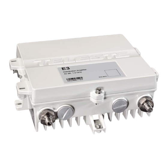
Legal declarations ................... 20 Introduction E3 is a compact dual output amplifier with wide 16…42 dB gain adjustment range making it suitable for both distribution purposes and line extender use. The E3 amplifier supports 1.2 GHz frequency range which ensures fulfilment of all future bandwidth needs. -
Page 3: Installation
Installation Mounting The E3 can be installed either into a street cabinet or to a sheltered outdoor environment. The amplifier should be installed vertically so that the external cable connectors and ventilation hole are facing downward. Figure 1 depicts for the positions of mounting brackets as well as other installation dimensions. -
Page 4: Interfaces
4(20) 9817032 Figure 1. E3 housing dimensions – top and side view Interfaces 9817024 Ground lug Input port Output port 2 Output port 1 Figure 2. Port locations The E3 has three dedicated cable connection points: Input and two outputs. -
Page 5: Coaxial Connections
5.4.2018 5(20) Coaxial connections The E3 amplifier requires pin-type connectors for all RF connections. The E3 amplifier has spring loaded seizure assemblies on coaxial ports that provide a tight connection with precise alignment between contact points. All coaxial output ports have a standard PG11 thread. Note that Teleste KDC327 (PG11–... -
Page 6: Powering
(galvanic isolator, see EN 60728-11). The E3 is available either with a remote or local powering option. The E3 has an integrated power supply that cannot be replaced. The following subsections describe the differences. -
Page 7: Front Panel
User Manual 59300623 Rev.001 5.4.2018 7(20) Front panel Figure 4. E3 front panel (remotely powered model) 1) Input port 6) Output test / injection point, F female 2) Input test point, F female (-20 dB directional coupler) (-20 dB resistive coupler) -
Page 8: Features
Features Diplex and output modules The E3 amplifier is delivered according to the ordering code. The installed diplex filters (Figure 4 positions 3 and 5) must be new 1.2 GHz types which are automatically detected by the software. The supported diplex filter types listed in Table 1. -
Page 9: Forward Path
The input and output amplifier stages are both based on high performance solutions which allow the user to set E3 outputs for high and low output levels. The output stage uses a GaN hybrid to improve RF performance over the entire 85 to 1218 MHz passband. -
Page 10: Return Path
10(20) Return path E3 amplifier supports 65 MHz, 85 MHz and 204 MHz return path. The return path bandwidth is automatically set according to the installed diplex filters. If diplex filter type cannot be detected, or the installed diplex filters are not the same type, the “Unknown module”... -
Page 11: Alarms
5.4.2018 11(20) Alarms The E3 alarms displayed in local user interface and PC / Android viewer are described in the table below. The alarm texts are displayed in separate rows in the local user interface. When the display is sleeping, slowly blinking dot “.” means no alarms and rapidly blinking “E”... -
Page 12: Local User Interface
E3 has a local user interface consisting of a 4*7-segment display and 3 buttons. This local UI can be used for E3 configuration in cases where E61 RIS module is not installed or the use of a PC, tablet or smartphone equipped with CATVisor Commander is not desired. - Page 13 Return Follows Forward [On / Off] Local UI PIN setting [0000 = disabled] Measured AC voltage [V] (Remote power model only) Measured internal temperature [°C] Software version Figure 5. E3 local user interface menu structure. Factory default values are in bold.
-
Page 14: E61 Ris Receiver With Usb
Note that E61 automatically updates E3 software if it detects different version that is included inside E61. Thus it is recommended to make sure the E61 software version is up to date before installing it into E3. See the “Software update” chapter for details. -
Page 15: Establishing Connection
5.4.2018 15(20) Establishing connection In addition to the local user interface, the E3 amplifier can also be configured with a PC, tablet or smartphone when E61 module is installed. Connection to E3 is possible using the following methods: Local configuration with a PC through E61 RIS receiver USB port CATVisor Commander 2.10 or later and up-to-date DUS100 user interface... -
Page 16: Software Update
E3 software can be only updated using E61 module. The E61 software includes the E3 software image. Every time E61 software starts it checks the E3 software version. If it does not match with the version of the E3 software image included in E61 software, the E61 automatically updates E3 software. -
Page 17: Viewer Pages
Viewer pages This chapter presents E3 graphical user interface (=”viewer”) pages when connecting to E3 with CATVisor Commander PC software via E61 module USB port using USB cable or AC6901 Bluetooth adapter. The same settings but in slightly different layout are also available when using an Android tablet or smartphone with Teleste Commander software. - Page 18 The “TEMP” field displays E3’s internal temperature. It is typically 10…25 degrees above ambient temperature depending on installation. The “AC” field is visible only with remote powered E3 model and shows the measured RMS value of the remote supply voltage. This value is calculated using sliding average and thus reacts quite slowly to changes.
- Page 19 The "Reset count" field shows the total number of resets. Security The PIN code can be enabled to protect the E3 local user interface from unauthorised access. When a value other than 0000 is entered, the correct PIN needs to be entered every time the local user interface is used. Note that the...
-
Page 20: Legal Declarations
This document is protected by copyright laws. Unauthorized distribution or reproduction of this document is strictly prohibited. Teleste reserves the right to make changes to any of the products described in this document without notice and all specifications are subject to change without notice.
Need help?
Do you have a question about the E3 and is the answer not in the manual?
Questions and answers