fafnir TORRIX Technical Documentation Manual
The magnetostrictive level sensor
Hide thumbs
Also See for TORRIX:
- Technical documentation manual (40 pages) ,
- Technical documentation manual (56 pages)
Table of Contents

Related Manuals for fafnir TORRIX


Summary of Contents for fafnir TORRIX
- Page 1 TORRIX The magnetostrictive level sensor Edition: 2020-04 Version: Art. no.: 207074 FAFNIR GmbH • Schnackenburgallee 149 c • 22525 Hamburg • Germany • Tel.: +49 / 40 / 39 82 07-0 • F: +49 / 40 / 390 63 39...
-
Page 2: Table Of Contents
Installation with flange ........................7 Installation on the bypass ....................... 7 Electrical connection .................... 9 Wiring diagram TORRIX ........................9 Wiring diagram TORRIX Ex ......................9 Cable length ............................10 Wiring … ............................... 12 5.4.1 … with cable gland ........................... 12 5.4.2... - Page 3 SIL 2 Certificate ..........................36 10.5 SIL 2 Safety Manual ......................... 40 © Copyright: Reproduction and translation are permitted only with the written consent of the FAFNIR GmbH. The FAFNIR GmbH reserves the right to carry out product alterations without prior notice. Contents...
-
Page 4: Characteristics
Technical documentation TORRIX M12, art. no. 350164 The TORRIX supplies a 4 … 20 mA output signal that is configured using buttons in the probe head, or a digital output signal as HART protocol. Probe lengths are possible from 100 mm ®... -
Page 5: Safety Instructions
Safety instructions The TORRIX level sensor is intended for level measurement of liquids in containers. The level sensor must be used exclusively for this purpose. The manufacturer accepts no liability for any form of damage resulting from improper use. The level sensor has been developed, manufactured and tested in accordance with the latest good engineering practices and generally accepted safety standards. -
Page 6: Design And Function
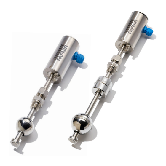
Design and function The design of the TORRIX level sensor is illustrated in the version with screw-in unit (see following figure). Inside probe head (1) of the level sensor, concealed by cap (2), are the protected terminal clamps and configuration buttons. The electrical connection is made on the side of the probe head via an M12 cable gland (or M16 x 1.5 adapter), an M12 male connector, or an M20... - Page 7 ② 1 – Magnetostrictive wire 2 – Current pulses 3 – Circular magnetic field 4 – Magnet ① 5 – Torsion wave ③ ⑤ ④ ⑤ Figure 2: Operating principle of the TORRIX level sensor Design and function Page 4/44...
-
Page 8: Installation
∅ 50 ∅ 50 Probe head Probe head Neck tube Screw-in unit Flange Probe tube Probe tube ø 12 ø 12 Float Float Adjusting Adjusting ring ring TORRIX screw-in unit TORRIX flange TORRIX Bypass Figure 3: TORRIX versions Page 5/44 Installation... -
Page 9: Installation With Screw-In Unit
During installation, take great care not to bend the probe tube, and protect the float from shock and impact loads. Installing a level sensor in areas exposed to a powerful external magnetic field is not permitted because this could impair gauging. The level sensor can also be fitted into containers from underneath. -
Page 10: Installation With Flange
To ensure reliable gauging, the probe tube must be fitted with no deformation on the outside. The distance between the probe and bypass tubes must be as small as possible. Only floats approved by FAFNIR can be used. Page 7/44 Installation... - Page 11 TORRIX Bypass TORRIX Bypass Distance between probe tube and float centre: max. distance Abstand Sondenrohr zu depends on the bypass float Schwimmermitte: max. Abstand abhängig vom Bypass-Schwimmer max. max. Magnet position Bypass float Magnetposition Bypass-Schwimmer Sondenrohr spannungsfrei Probe tube tension-free...
-
Page 12: Electrical Connection
4...20 mA Line resistance Leitungswiderstände Power supply Hilfsenergie Figure 8: Wiring diagram TORRIX Ex Power supply: U = 30 V DC Minimum supply voltage: U = 8 V Permissible total resistance (including cable resistance and load): ΣR = (U - U ) / 0.0215 A... -
Page 13: Cable Length
The intrinsically safe version of the TORRIX Ex level sensor, when installed in a potentially explosive atmosphere, is permitted to be connected only to isolating amplifiers that have been certified by a recognised inspection authority and offer electrical outputs that meet the following conditions: 30 V ≤... - Page 14 The following table shows the maximum total resistances at different supply voltages, and cable resistances at various cross-sections: Supply volt- Max. total re- Cable cross- Cable resistance For connection age [V] sistance [Ω] section per m copper cable housing HPH Ex d [mm²] [Ω/m] suitable (yes/no)
-
Page 15: Wiring
Wiring … 5.4.1 … with cable gland The wiring must be carried out only with the power disconnected. For the wiring of the level sensor, proceed as follows: Unscrew probe head cover (1) using an open-ended spanner. Loosen union nut (2) of screwed cable gland (3). 4 mA 20 mA Cal/Err... -
Page 16: With M12 Connection
Pin 4 Pin assignment of the M12 female connector of the FAFNIR connection cable The connection cable between the TORRIX … and the associated equipment must have the following properties: 2-wire unshielded cable • For Ex applications colour blue or marked blue (cable for intrinsically safe power •... -
Page 17: Adjustment
® Measuring span at the level sensor To enable configuration of the 4 mA and 20 mA points at the TORRIX level sensor, two but- tons and an LED (light emitting diode) are provided near the terminals inside the probe head. -
Page 18: Current Consumption In Failure Mode
To define a reference point: Move the float to the desired reference point and briefly press (0.1 to 2 seconds) the “4 mA” button (2) to define a current consump- − tion of 4 mA at this position briefly press (0.1 to 2 seconds) the “20 mA” button (3) to define a current con- −... - Page 19 The new measuring range configuration is not stored until the level sensor re- verts automatically from adjustment mode to configuration mode and the LED goes out. The new configuration is retained even if the level sensor is subse- quently disconnected from the power supply. Screw probe head cap (1) back on.
-
Page 20: Maintenance
Return shipment Before returning any FAFNIR equipment the Return Material Authorization (RMA) by the FAFNIR customer support is required. Please contact your account manager or the customer service to receive the instructions on how to return goods. The return of FAFNIR equipment is possible only with authorization by the FAFNIR customer service. -
Page 21: Technical Data
Cable diameter 5 … 10 mm Temperature -40 … +85 °C Probe tube Length 200 to 6,000 mm (to order) Length TORRIX Flex 1.5 m … 22 m Diameter 12 mm (other diameters on request) Material: 1.4571 standard (Hastelloy, or other materials on request) Measuring range freely adjustable (>... - Page 22 Accuracy Linearity better than ±0.2 mm or ±0.01 %, Digital component better than ±0.001 % per K NT/LT Repetition accuracy better than 0.05 mm Resolution better than 10 µm Accuracy Linearity better than ±0.5 mm or ±0.025 %, Digital component better than ±0.01 % per K HT/HHT Repetition accuracy better than 0.1 mm...
-
Page 23: Float
Float The float is an essential component of the level sensor that must be matched to the medium in respect of density, pressure resistance and material durability. The following floats are exchangeable and can be ordered separately. Other float types and materials are available on request. -
Page 24: List Of Figures
List of figures Figure 1: TORRIX level sensor ......................... 3 Figure 2: Operating principle of the TORRIX level sensor..............4 Figure 3: TORRIX versions ..........................5 Figure 4: Installation with screw-in unit ...................... 6 Figure 5: Tightening the compression fitting ................... 7 Figure 6: Installation on the bypass...................... -
Page 32: Instructions
(TORRIX Ex ... Flex, VISY-Stick ... Flex ...) as well as types with plastic coating against very aggressive me- dia (TORRIX Ex … PL) can be used for all gases of groups IIA and IIB. The temperature measuring chain VISY-Stick ... Temp ... and all other filling level sensors can be used for all gases of groups IIA, IIB and IIC. - Page 33 For the filling level sensors with screw terminals type TORRIX Ex ... and TORRIX Ex HART ... the terminal designation is "+" and "-" For devices with M12 plug, the pin assignments are as follows: TORRIX Ex C …...
- Page 34 Ex ia IIC T6…T4 Ga/Gb Ex ia IIC T6…T4 Gb Ex ia IIIC T160 °C Da TORRIX Ex …-A / TORRIX Ex … Flex / TORRIX Ex … PL Ex ia IIB T6…T4 Ga Ex ia IIB T6…T4 Ga/Gb Ex ia IIB T6…T4 Gb Ex ia IIIC T160 °C Da...
- Page 35 TORRIX Ex SC…-A / TORRIX Ex SC… Flex / TORRIX Ex SC… PL / VISY-Stick Advanced … / VISY-Stick … Flex … Ex ia IIB T6…T5 Ga Ex ia IIB T6…T4 Ga/Gb Ex ia IIB T6…T4 Gb Ex ia IIIC T135 °C Da TORRIX Ex C…...
- Page 36 When using the equipment in potentially explosive gas atmospheres please consult table 3 to table 5 for the maximum temperatures depending on temperature classes and category respectively equipment protection levels. Type TORRIX Ex SC… / VISY-Stick … Temperature class Category 1G resp. EPL Ga (filling level sensor completely installed in zone 0) -20 °C …...
- Page 37 Type TORRIX Ex … / TORRIX Ex C… / TORRIX Ex RS485… / TORRIX Ex TAG… / VISY-Stick … RS485 Temperature class Category 1G resp. EPL Ga (filling level sensor completely installed in zone 0) ≤ 100 mA: -20 °C … +40 °C ≤...
- Page 38 -40 °C … +77 °C + 110 °C Observe EN 60079-14 -40 °C … +85 °C Types TORRIX Ex C… / TORRIX Ex RS485… / TORRIX Ex TAG… / VISY-Stick … RS485 ≤ 100 mA: T + 40 °C -40 °C … +85 °C Observe EN 60079-14 ≤...
-
Page 43: Sil 2 Safety Manual
It must be ensured that there are no strong magnetic fields in the area of the probe tube. In addition, the safe use with adhering liquids is not guaranteed. Page 1/5 FAFNIR GmbH • Schnackenburgallee 149 c • 22525 Hamburg • Tel.: +49 / (0)40 / 39 82 07-0 • www.fafnir.de • info@fafnir.de... - Page 44 Magnetostrictive level and environmental sensor with up to five temperature sensors in the sensor tube VISY- Volume Information System Type code III.a2: Level sensor VISY-Stick … Page 2/5 FAFNIR GmbH • Schnackenburgallee 149 c • 22525 Hamburg • Tel.: +49 / (0)40 / 39 82 07-0 • www.fafnir.de • info@fafnir.de...
- Page 45 Before putting into service, all devices must be checked of right installation and connection. The elec- trical supply, as well of connected devices, must be checked. Page 3/5 FAFNIR GmbH • Schnackenburgallee 149 c • 22525 Hamburg • Tel.: +49 / (0)40 / 39 82 07-0 • www.fafnir.de • info@fafnir.de...
- Page 46 Page 4/5 FAFNIR GmbH • Schnackenburgallee 149 c • 22525 Hamburg • Tel.: +49 / (0)40 / 39 82 07-0 • www.fafnir.de • info@fafnir.de...
- Page 47 Table IV: Safety related codes Additional requirements for software elements There are no requirements for software elements. Page 5/5 FAFNIR GmbH • Schnackenburgallee 149 c • 22525 Hamburg • Tel.: +49 / (0)40 / 39 82 07-0 • www.fafnir.de • info@fafnir.de...
- Page 48 FAFNIR GmbH Schnackenburgallee 149 c 22525 Hamburg, Germany T: +49 / 40 / 39 82 07– 0 F: +49 / 40 / 390 63 39 E-mail: info@fafnir.com Web: www.fafnir.com...
Need help?
Do you have a question about the TORRIX and is the answer not in the manual?
Questions and answers