Table of Contents

Related Manuals for fafnir CONDURIX Series


Summary of Contents for fafnir CONDURIX Series
- Page 1 Technical Documentation CONDURIX The potentiometric level sensor Edition: 2016-08 Version: Art. no.: 207134 FAFNIR GmbH • Schnackenburgallee 149 c • 22525 Hamburg, Germany • Tel.: +49 / 40 / 39 82 07–0 • Fax: +49 / 40 / 390 63 39...
- Page 2 Table of Contents...
-
Page 3: Table Of Contents
EC-Type Examination Certificate ............... 15 10.3 Safety instructions .................... 18 © Copyright: Reproduction and translation are permitted only with the written consent of the FAFNIR GmbH. FAFNIR GmbH reserves the right to make changes to products without prior notice. Table of Contents... -
Page 4: Range Of Application
Range of application The purpose of the CONDURIX level sensor is to provide continuous level gauging of elec- trically conductive liquids (> 1 μS/cm). During the measurement no insulating layer must be formed on the probe tube. The level sensor is available in lengths of 200 to 6,000 mm. With the “single-rod probe”... -
Page 5: Safety Instructions
Safety instructions The purpose of the CONDURIX level sensor is to provide continuous level gauging of liq- uids. The level sensor must be used exclusively for this purpose. The manufacturer accepts no liability for any form of damage resulting from improper use. The level sensor has been developed, manufactured and tested in accordance with the latest good engineering practices and generally accepted safety standards. -
Page 6: Design And Function
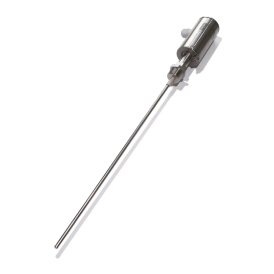
Design and function The design of the CONDURIX level sensor is illustrated in Figure 1 with the screw-in unit version as an example. Inside the sensor head (1) of the level sensor and concealed by a cap (2) are the protected terminals and configuration buttons. The electrical connection is established by means of an M16x1.5 screwed cable gland (3) and screw terminals or by an M12 plug-in connection. - Page 7 The fill level is calculated from the ratio of the measured voltages by a microcontroller. The ratio of the two voltages also enables the orientation of the CONDURIX sensor to be detected, i.e. whether the sensor has been installed from top down or bottom up. The level sensor is fed from a 2-wire 4 …...
-
Page 8: Installation
Installation All local safety and accident prevention regulations not expressly referred to herein must be observed. CONDURIX DU Cap, SW 19 Cap, SW 19 removable removable Cable Cable gland gland M16x1.5 M16x1.5 Sensor head Sensor head Connector for Connector for equipotential bonding equipotential bonding Screw-in... -
Page 9: Condurix Mono (Single Rod)
CONDURIX Mono (single rod) With the single-rod probe, the tank acts as the counter electrode. For this reason, the material on the inside of the tank must be conductive and there must be good electrical contact between the tank and the sensor head. For this purpose, the potential equaliza- tion terminal must be connected to the tank. -
Page 10: Electrical Connection
Electrical connection For the wiring of the level sensor, you need a two-core unshielded cable, which is termi- nated inside the sensor head of the level sensor. It is essential that the correct cross section be selected: the supply voltage at the level sen- sor must not fall below 8 V in the event of maximum current consumption (21.5 mA). - Page 11 The connector on the underside of the sensor head (5) can be used for earthing or equipotential bonding. With the CONDURIX Mono, the potential equalization terminal (5) must be connected to the electrically conductive tank. Protect the sensor head against the ingress of water. An external cable diameter of 5 to 10 mm ensures reliable sealing of the cable gland.
-
Page 12: Parametrisation
Parametrisation Measuring span at the level sensor To enable configuration of the 4 mA and 20 mA points at the CONDURIX level sensor, two buttons and an LED (light emitting diode) are provided near the terminals inside the probe head. By default, the level sensor is set to maximum span with 4 mA at the probe base and 20 mA at the sensor head. -
Page 13: Current Consumption In Failure Mode
In configuration mode, the 4 mA or 20 mA point, or both reference points, can be modi- fied in any order. To define a reference point while the sensor is in configuration mode • briefly (1-2 seconds) press “4 mA” button (2) to define a current consumption of 4 mA for the present immersed position of the sensor. -
Page 14: Maintenance
Overhaul The level sensor is maintenance-free. Return shipment Before returning any FAFNIR equipment the Return Material Authorization (RMA) by the FAFNIR customer care is required. Please contact your account manager or customer service for instructions on how to return goods. -
Page 15: Technical Data
Technical Data Electrical connection 2-wire terminal Power supply 8 … 30 V DC Output signal 4 … 20 mA “Empty” signal 3.8 mA or 20.5 mA Error message 21.5 mA or 3.6 mA Process Connection Screw-in unit (standard R 3/4) Flange on request For material, see probe tube Sensor head... -
Page 16: List Of Figures
List of figures Figure 1: The CONDURIX level sensor ................3 Figure 2: Measured value output ..................4 Figure 3: CONDURIX variants ..................5 Figure 4: Connecting the CONDURIX level sensor ............7 Figure 5: Parametrisation measuring span ............... 9 Page 13/20 List of figures... -
Page 21: Safety Instructions
10.3 Safety instructions Level Gauge CONDURIX Ex … Edition: 04.2011 Range of application The intrinsically safe equipment CONDURIX Ex … is used for the continuous measurement of liquid levels. The level sensor operates only in electrically conductive liquids (conductivity ≥ 1 μS/cm). If the level sensor is inserted into a tank with non-conducting wall, the sensor must be equipped with a counter electrode, e. - Page 22 … maintenance, overhaul and repair The device is maintenance-free. In case of a defect, please send back the level sensor to the manu- facturer FAFNIR. Equipment marking 1 Manufacturer: FAFNIR GmbH, Hamburg 2 Type designation: CONDURIX Ex … 3 Serial number: Ser. N°: …...
- Page 23 Technical data The level sensor is connected to a 4 … 20 mA interface, which provides the auxiliary energy simulta- neously. The connection is via the + and - terminals. The sealing of the cable is given by a cable gland or by a conduit system.
- Page 24 FAFNIR GmbH Schnackenburgallee 149 c 22525 Hamburg, Germany Tel.: +49 / 40 / 39 82 07–0 Fax: +49 / 40 / 390 63 39 E-mail: info@fafnir.com Web: www.fafnir.com...
Need help?
Do you have a question about the CONDURIX Series and is the answer not in the manual?
Questions and answers