Table of Contents

Related Manuals for fafnir HART TORRIX


Summary of Contents for fafnir HART TORRIX
- Page 1 Technical Documentation TORRIX The magnetostrictive level sensor Edition: 2018-11 Version: 18 Art. no.: 207074 FAFNIR GmbH • Schnackenburgallee 149 c • 22525 Hamburg • Germany • Tel.: +49 /40 / 39 82 07-0 • Fax: +49 /40 / 390 63 39...
-
Page 2: Table Of Contents
Table of contents Overview....................1 Safety instructions ................. 2 Design and function ................3 Installation ....................5 Installation with screw-in unit ................6 Installation with flange ..................7 Installation on the bypass ................... 7 Electrical connection ................9 Wiring diagram TORRIX ..................9 Wiring diagram TORRIX Ex ................. - Page 3 EC Type-Examination Certificate ............... 25 10.4 Instructions ...................... 31 © Copyright: Reproduction and translation are permitted only with the written consent of FAFNIR GmbH. FAFNIR GmbH reserves the right to carry out product alterations without prior notice. Table of contents...
-
Page 4: Overview
Overview The high-precision TORRIX level sensor is designed to provide continuous gauging of liquid media levels in tanks. The measuring principle used by the sensor exploits the physical effect of magnetostriction and is largely unaffected by temperature. This method is particularly ideal where level measurements are required to be extremely accurate, such as in the chem- ical industry. -
Page 5: Safety Instructions
Safety instructions The purpose of the TORRIX level sensor is to gauge liquid levels in tanks. The level sensor must be used exclusively for this purpose. The manufacturer accepts no liability for any form of damage resulting from improper use! The level sensor has been developed, manufactured and tested in accordance with the latest good engineering practices and generally accepted safety standards. -
Page 6: Design And Function
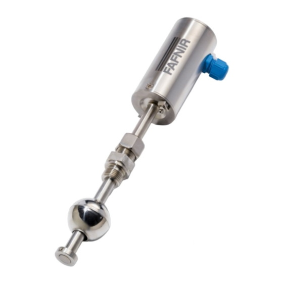
Design and function The design of the TORRIX level sensor is illustrated in the version with screw-in unit (see following figure). Inside probe head (1) of the level sensor, concealed by cap (2), are the protected terminal clamps and configuration buttons. The electrical connection is established by an M16 x 1.5 screwed cable gland (3) or M12 plug-in connection at the top of the probe head and by earth connector (4) at the bottom of the probe head (see chapters “Installation”... - Page 7 The measuring principle illustrated in the following figure exploits the physical effect of magnetostriction and is largely unaffected by temperature. The probe tube contains a ten- sioned wire (1) made of magnetostrictive material. The sensor electronics transmit current pulses (2) through the wire, which generate a circular magnetic field (3). A magnet (4) inside the float acts as the filling level sensor.
-
Page 8: Installation
Installation When installing and maintaining the level sensor in potentially explosive ar- eas, the national rules must be observed (Explosion Protection Regulations, In- dustrial Health and Safety Regulations, Equipment Safety Regulations and the specific conditions of the EC-Type Examination Certificates). The generally accepted rules of engineering and these operating instructions must be ob- served. -
Page 9: Installation With Screw-In Unit
During installation, take great care not to bend the probe tube, and pro- tect the float from shock and impact loads. Installing a level sensor in areas exposed to a powerful external magnetic field is not permitted because this could impair gauging. The level sensor can also be fitted into the tank from underneath. -
Page 10: Installation With Flange
To ensure reliable gauging, the probe tube must be fitted with no defor- mation on the outside. The distance between the probe and bypass tubes must be as small as possible. Only floats approved by FAFNIR can be used. Page 7/37 Installation... - Page 11 TORRIX Bypass TORRIX Bypass Distance between probe tube Abstand Sondenrohr zu and float centre: max. distance Schwimmermitte: max. Abstand depends on the bypass float abhängig vom Bypass-Schwimmer max. max. Magnet position Bypass float Magnetposition Bypass-Schwimmer Probe tube tension-free Sondenrohr spannungsfrei mounted (undeformed) montiert (unverformt) Bypass tube...
-
Page 12: Electrical Connection
Electrical connection Wiring diagram TORRIX The level sensor without Ex approval is installed in accordance with the following wiring diagram: Power supply Spannungsquelle TORRIX = 30 V = 8 V Load Bürde Leitungswiderstände Line resistance Figure 7: Wiring diagram TORRIX Power supply: U = 30 V DC Minimum supply voltage: U... -
Page 13: Cable Length
The intrinsically safe version of the TORRIX Ex level sensor, when installed in a potentially explosive atmosphere, is permitted to be connected only to iso- lation amplifiers that have been certified by a recognised inspection authority and offer electrical outputs that meet the following conditions: ≤... - Page 14 The following table shows the maximum total resistances at different supply voltages, and cable resistances at various cross-sections: Supply volt- Max. total re- Cable cross- Cable resistance For connection sistance [Ω] age [V] section per m copper ca- housing HPH Ex d ble [Ω/m] [mm²] suitable (yes/no)
-
Page 15: Wiring
Wiring … 5.4.1 … with cable gland Wiring work may only be performed with the power disconnected. For the wiring of the level sensor, proceed as follows: Unscrew probe head cap (1) using an open-ended spanner. Loosen union nut (2) of screwed cable gland (3). 4 mA 20 mA Cal/Err... -
Page 16: With M12 Connector
Wiring work may only be performed with the power disconnected. • If not already connected, plug the coupling of the FAFNIR connection cable onto the M12 connector of the probe head. First tighten the union nut of the M12 connector by hand and then use an open-ended spanner to tighten the nut fur- ther 180°. -
Page 17: Adjustment
Adjustment Versions that support the HART protocol enable the adjustment described ® below to be carried out remotely without the probe head having to be opened. Measuring span at the level sensor To enable configuration of the 4 mA and 20 mA points at the TORRIX level sensor, two buttons and an LED (light emitting diode) are provided near the terminals inside the probe head. -
Page 18: Current Consumption In Failure Mode
− briefly press (0.1 to 2 seconds) “4 mA” button (2) to define a current consump- tion of 4 mA at this position − briefly press (0.1 to 2 seconds) “20 mA” button (3) to define a current consump- tion of 20 mA at this position When the “4 mA”... -
Page 19: Maintenance
Return shipment Before returning any FAFNIR equipment the Return Material Authorization (RMA) by the FAFNIR customer service is required. Please contact your account manager or the customer service to receive the instructions on how to return goods. The return of FAFNIR equipment is possible only with authorization by the FAFNIR customer care. -
Page 20: Technical Data
Technical data Sensor Electrical connection 2-wire terminal 4 to 20 mA (3.8 … 20.5 mA) current consumption for level display 21.5 mA or 3.6 mA current consumption in failure mode Supply voltage: TORRIX 8 … 30 V DC TORRIX EX 8 …... - Page 21 Accuracy Linearity better than ±0.2 mm or ±0.01 %, NT/LT digital component better than ±0.001 % per K Repetition accuracy better than 0.05 mm Resolution better than 10 µm Accuracy Linearity better than ±0.5 mm or ±0.025 %, HT/HHT digital component better than ±0.01 % per K Repetition accuracy better than 0.1 mm Resolution better than 50 µm...
-
Page 22: Float
Float The float is a key component of the level sensor that must be matched to the medium in respect of density, pressure resistance and material durability. The following floats are exchangeable and are available to order separately. Other float types and materials are available on request. -
Page 23: List Of Figures
List of figures Figure 1: TORRIX level sensor ..................3 Figure 2: Operating principle of the TORRIX level sensor ..........4 Figure 3: TORRIX versions ....................5 Figure 4: Installation with screw-in unit ................6 Figure 5: Compression fitting fixing ................. 7 Figure 6: Installation on the bypass .................. - Page 34 • Frictions on non-conductive components are to be avoided; • The float must not be cleaned in a dry state. • Page 1/7 FAFNIR GmbH Schnackenburgallee 149 c 22525 Hamburg Tel.: +49 / (0)40 / 39 82 07-0 www.fafnir.de info@fafnir.de ...
- Page 35 VISY-Stick … VISY-Stick … RS485 VISY-Stick … TLS A (+) B (-) Table 1: Terminal assignment of the sensors Page 2/7 FAFNIR GmbH Schnackenburgallee 149 c 22525 Hamburg Tel.: +49 / (0)40 / 39 82 07-0 www.fafnir.de info@fafnir.de ...
- Page 36 Warning: The type VISY-Stick Sump … and floats made of non-conductive plastic must only be cleaned with a damp cloth, to minimize the risk of electrostatic charging. Equipment marking Manufacturer: FAFNIR GmbH, 22525 Hamburg Type designation: TORRIX Ex … / VISY-Stick … Certificate number: TÜV 99 ATEX 1496 X...
- Page 37 CE marking: 0044 Technical Data See instructions for technical data * Warning is only valid for sensor VISY-Stick Sump … Page 4/7 FAFNIR GmbH Schnackenburgallee 149 c 22525 Hamburg Tel.: +49 / (0)40 / 39 82 07-0 www.fafnir.de info@fafnir.de ...
- Page 38 -40 °C … +300 °C -40 °C … +450 °C Table 3: Operating temperatures of the filling level sensors in basic version (without interface board) Page 5/7 FAFNIR GmbH Schnackenburgallee 149 c 22525 Hamburg Tel.: +49 / (0)40 / 39 82 07-0 www.fafnir.de...
- Page 39 Temperature range: -20 °C … +60 °C Pressure range: 0.8 bar to 1.1 bar Oxidants: Air (oxygen content approx. 21 %) Page 6/7 FAFNIR GmbH Schnackenburgallee 149 c 22525 Hamburg Tel.: +49 / (0)40 / 39 82 07-0 www.fafnir.de info@fafnir.de ...
- Page 40 2. When using plastic parts, pay attention to electrostatics. For the assessment of the temperatures see section 5.6.3.3 of EN 60079-14:2014 Page 7/7 FAFNIR GmbH Schnackenburgallee 149 c 22525 Hamburg Tel.: +49 / (0)40 / 39 82 07-0 www.fafnir.de...
- Page 41 Blank Page...
- Page 42 Blank Page...
- Page 43 Blank Page...
- Page 44 FAFNIR GmbH Schnackenburgallee 149 c 22525 Hamburg, Germany Tel.: +49 / 40 / 39 82 07–0 Fax: +49 / 40 / 390 63 39 E-mail: info@fafnir.com Web: www.fafnir.com...
Need help?
Do you have a question about the HART TORRIX and is the answer not in the manual?
Questions and answers