Table of Contents
Advertisement
Quick Links
Advertisement
Table of Contents

Related Manuals for fafnir TORRIX XTS Series


Summary of Contents for fafnir TORRIX XTS Series
- Page 1 Technical Documentation TORRIX … XTS … Magnetostrictive Level Sensor with Display Edition: 2023-04 Version: 1 Art. no.: 350372 FAFNIR GmbH • Schnackenburgallee 149 c • 22525 Hamburg • Germany • T.: +49 /40 / 39 82 07-0 • Web: www.fafnir.com...
-
Page 2: Table Of Contents
Table of Contents Characteristics ......................1 TORRIX XTS Variants .......................... 2 Safety Instructions ....................3 Design and Function ....................4 TORRIX XTS with Screw Connection .................... 5 TORRIX XTS with Flange ........................6 TORRIX XTS for Bypass ........................7 Installation ......................8 Installation with screw-in unit ....................... - Page 3 EU-Type Examination Certificate ....................33 11.3 Instructions ............................41 © Copyright: Reproduction and translation are permitted solely with the written consent of the FAFNIR GmbH. The FAFNIR GmbH reserves the right to carry out product alterations without prior notice. Table of contents...
-
Page 4: Characteristics
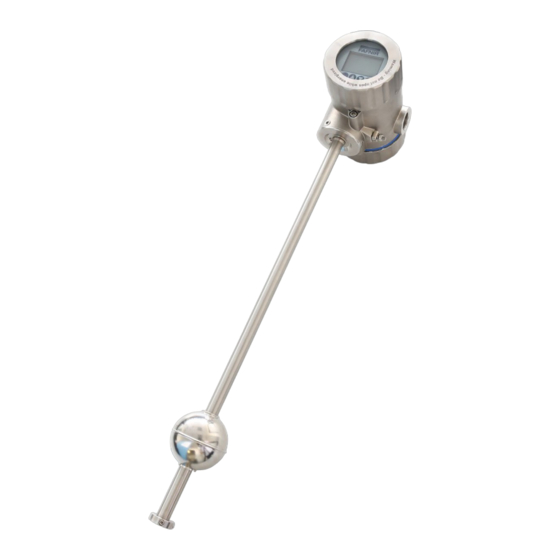
Characteristics The TORRIX ... XTS ... is a high-precision level sensor from the TORRIX series with an addi- tional display (XTS) for showing up to 3 different TORRIX measured values on the sensor head. The sensor has been developed for continuous level measurement of liquid media in con- tainers. -
Page 5: Torrix Xts Variants
TORRIX XTS Variants Process temperature Maximum temperature -40 °C … +450 °C High temperature -40 °C … +250 °C Low temperature -65 °C … +125 °C Normal temperature -40 °C …(+85) +125 °C Rigid sensor tube with 12 mm diameter Sensor tube not centered on the sensor head (Bypass) Flex ... -
Page 6: Safety Instructions
REACH Regulation The TORRIX sensors contain a lead-titanium-zirconium-oxide, which belongs to the substances of very high concern (SVHC) according to Regulation (EG) No. 1907/2006 (REACH). A corresponding note can be found on our website at: www.fafnir.com. Page 3/47 Safety Instructions... -
Page 7: Design And Function
Design and Function The level sensors consist of a probe head (1) and a probe tube (4) made of stainless steel. The probe tube is height-adjustable with a screw-in body (3) or mounted with a flange in the tank or outside the tank as a bypass. A float (5) for measuring the product filling level and another float (6) for continuous interface measurement move on the probe tube. -
Page 8: Torrix Xts With Screw Connection
TORRIX XTS with Screw Connection Sondenkopf / Probe head Probe head Display unit Displayeinheit / Display module Verschluss- Screw plug schraube / M20x1.5 Screw plug M20×1,5 Erdungs- Earth connector anschluss / Earth connector Locking screw Verschraubung Screw connection nach Auftrag / on order Screw connection on order... -
Page 9: Torrix Xts With Flange
TORRIX XTS with Flange Probe head Display unit Screw plug M20x1.5 Earth connector Locking screw Flange depending on order Probe tube Ø12 Product float Guard ring dismountable Figure3: TORRIX XTS F (Flange) Design and Function Page 6/47... -
Page 10: Torrix Xts For Bypass
TORRIX XTS for Bypass Distance probe tube to float centre: max. distance depending on the bypass float Probe head Display unit Screw plug M20x1.5 Locking screw Earth connector Bypass float Bypass tube Magnet position Probe tube stressfree mounted (undeformed) Spacer Probe mounting (non-magnetic) SECTION A-A... -
Page 11: Installation
Installation This section describes how to install the level sensor depending on the type of the device (see the following figures). When installing and maintaining the level sensor in potentially explosive areas, the national rules must be observed (Explosion Protection Regulations, Indus- trial Health and Safety Regulations, Equipment Safety Regulations and specific conditions of the EU-Type Examination Certificates). -
Page 12: Installation With Screw-In Unit
Installation with screw-in unit Insert the level sensor into the tank (see following figure): Loosen both set screws, remove circlip (1) and float (2) from probe tube (3). Figure 5: Installation with screw-in unit Removing the float is required only if it does not fit through the installation opening in the tank. -
Page 13: Installation With Flange
Installation with flange The probe tube is firmly welded to the flange, so the installation length cannot be changed. Fasten flange and seal with the flange bolts and nuts. The screws or nuts and the seals are the responsibility of the operating company and must be chosen depending on the fluid. The fasteners and seals must comply with the requirements of the standards EN 1092-1, EN 1514 and EN 1515. -
Page 14: Electrical Connection
Electrical connection Connection Diagrams 5.1.1 Wiring diagram TORRIX XTS The level sensor without Ex approval is installed according to the following wiring diagram: Power supply Spannungsquelle TORRIX XTS = 50 V Power supply = 30 V TORRIX = 12 V = 8 V Load Bürde... -
Page 15: Wiring Diagram Torrix Ex Xts
5.1.2 Wiring diagram TORRIX Ex XTS The level sensor TORRIX Ex XTS with Ex i approval (intrinsically safe) is installed in a poten- tially explosive atmosphere according to the following wiring diagram: TORRIX Ex XTS Isolating amplifier (example) TORRIX Trennverstärker (Ex-Ausführung) (Beispiel) 12 …... -
Page 16: Wiring Diagram Torrix Exd Xts
5.1.3 Wiring diagram TORRIX Exd XTS The TORRIX Exd XTS level sensor with Ex d approval is installed in a potentially explosive atmosphere according to the following wiring diagram: Power supply Spannungsquelle TORRIX Exd XTS = 50 V TORRIX = 30 V 12 …... -
Page 17: Maximum Length Of The Connection Cable
Maximum Length of the Connection Cable The permissible total resistance of the cable and the load (see chapter 5.1.1) must not be exceeded. The cable (length and cross-section) must be chosen so that the supply voltage will not fall below the sensor-specific minimum voltage (12 V) in the case of the highest current consumption (21.5 mA). -
Page 18: Wiring
Wiring The TORRIX XTS level sensors may only be wired with the power disconnected. The terminal compartment is accessible after removing the rear screw cover from the probe head. To do this, screw the locking screw of the cover into the housing with a 3 mm Allen key. After the wiring has been completed, the cover must be screwed on again and secured against unintentional loosening. -
Page 19: Wiring The Torrix (Ex) Xts
5.3.1 Wiring the TORRIX (Ex) XTS A + - B Figure Terminal compartment of TORRIX (Ex) XTS Signal Connection Used internally Sensor voltage Sensor voltage – Used internally Pin assignment of the 4-pin PCB terminal clamp in the terminal compartment The connection cable between the (intrinsically safe) TORRIX (Ex) XTS and the associated equipment must have the following properties: 2-wire unshielded cable... -
Page 20: Wiring The Torrix (Exd) Xts With Heater
5.3.2 Wiring the TORRIX (Exd) XTS with Heater A + - B Figure Terminal compartment of TORRIX (Exd) XTS Signal Connection Used internally Sensor voltage Sensor voltage – Used internally Pin assignment of the 4-pin PCB terminal clamp in the terminal compartment For the extended temperature range (-55 °C to +85 °C), the TORRIX (Exd) XTS is additionally equipped with a heater for the display. -
Page 21: Indication And Adjustment Module
Closed housing When the housing is closed, the operation is done with a magnetic pen, the FAFNIR magnetic pen, effecting through the display glass. For this purpose, 4 magnetic sensors are arranged under the membrane keyboard in the area of the respective keys. -
Page 22: Arrangement Of The Keys / Magnet Sensors
6.2.1 Arrangement of the keys / magnet sensors The following figure shows the display with a membrane keyboard and the FAFNIR magnetic pen. Figure 12: Membrane keyboard and FAFNIR magnetic pen 6.2.2 Function of the keys / magnet sensors The individual keys / magnet sensors have the following functions: •... -
Page 23: Measured Value Display
• Change from the measured value display to the main menu • Jump to the selected submenu • Forward to the next position, when entering text or multi-digit numbers • Select and save value for parameter Measured value display The following information is shown in the measured value display: TAG (measuring point) •... -
Page 24: Simulation
Measured value display with two measured values: Figure14: Measured value display with two measured values Measured value display with three measured values: Figure 15: Measured value display with three measured values Simulation A configured simulation is only started when you switch back from the configuration menu to the measured value display. -
Page 25: Error Display
Error display Errors detected by the TORRIX XTS are shown as error messages with plain text information on the display. Figure 16: Error display, supply voltage too low The following error messages can be displayed: • Signature error • TORRIX XTS parameter error •... -
Page 26: Adjustment
Adjustment TORRIX XTS Configuration The configuration is done with the computer using the FAFNIR HART-Setup configuration tool, see technical documentation FAFNIR HART SETUP art. no. 350225 Configurations for the TORRIX XTS can also be done using the indicating and adjustment module. - Page 27 If there are more than the currently displayed menu items, this is indicated by an arrow in the lower right corner of the display. The menu items that are not visible can be shown by scrolling up or down using the arrow keys. The configuration will automatically be exited after 2 minutes if there is no further operation.
-
Page 28: Menu Structure
Menu Structure Main Menu / Configuration // Display /// Language The active language is always named above after the equals sign: ➤ English ➤ Deutsch ➤ Français ➤ Español ➤ Português ➤ Italiano ➤ Pусский Main Menu / Configuration // Display /// TAG Enter the measuring point designation (8 characters). - Page 29 Main Menu / Configuration // Output /// Variable The variable to which to the 4 to 20 mA signal refers is determined here. Main menu / Configuration // Output /// 4 mA point Setting the 4 mA point of the probe (in units of length) Main menu / Configuration // Output /// 20 mA point Setting the 20 mA point of the probe (in units of length) Main Menu / Configuration // Output /// Alarm current...
- Page 30 Main menu / Diagnosis // Simulation /// Operating mode Off: Simulation disabled Fixed: the mA value set for "Low" is output Alternating: the mA value set for "Low" and for "High" are output alternately Main menu / Diagnosis // Simulation /// Operating Variable Variable in the simulation (e.g.
-
Page 31: Maintenance
Return Shipment Before returning any FAFNIR equipment, the Return Material Authorization (RMA) from FAFNIR customer service is required. Please contact your account manager or the customer service to receive the instructions on how to return goods. The return of FAFNIR products is only possible after approval by the FAFNIR customer service. -
Page 32: Technical Data
Technical Data Sensor Electrical connection TORRIX (Ex) XTS 2-wire connection 4 … 20 mA (3.8 … 20.5 mA) current consumption for level indication 21.5 mA or 3.6 mA current consumption in the event of a fault Supply voltage TORRIX (Exd ) XTS 12 …... -
Page 33: Float
Measuring accuracy Linearity better than ±1 mm or ±0.05 %, better than ±0.01 % per K Digital component Repetition accuracy better than 0.1 mm HT/HHT Resolution better than 50 µm Measuring accuracy Linearity better than ±0.2 mm or ±0.01 %, better than ±0.001 % per K Digital component Repetition accuracy better than 0.05 mm NT/LT (on request) -
Page 34: List Of Figures
Figure 10: Terminal compartment of TORRIX (Ex) XTS ............... 16 Figure 11: Terminal compartment of TORRIX (Exd) XTS ..............17 Figure 12: Membrane keyboard and FAFNIR magnetic pen ............19 Figure 13: Measured value display with one measured value ............20 Figure14: Measured value display with two measured values ............ -
Page 36: Eu-Type Examination Certificate
Directive 2014/34/EU Certificate Number TÜV 99 ATEX 1496 X Issue: for the product: Filling level sensors type VISY-Stick … and type TORRIX Ex… of the manufacturer: FAFNIR GmbH Address: 22525 Hamburg Germany Order number: 8003035365 Date of issue:... - Page 37 S C H E D U L E (13) (14) EU-Type Examination Certificate No. TÜV 99 ATEX 1496 X Issue 03 (15) Description of product: The filling level sensors type VISY-Stick … and type TORRIX Ex… are used for continuous measurement of liquid levels within potentially explosive areas.
- Page 38 Schedule to EU-Type Examination Certificate No. TÜV 99 ATEX 1496 X Issue 03 VISY-Stick … • • VISY-Stick (Flex) Temp • VISY-Stick … RS485 VISY-Stick (Flex) Temp RS485 • II 1 G Ex ia IIC T6…T1 Ga TORRIX Ex… II 1/2 G Ex ia IIC T6…T1 Ga/Gb •...
- Page 39 Schedule to EU-Type Examination Certificate No. TÜV 99 ATEX 1496 X Issue 03 Electrical data: VISY-Stick …; VISY-Stick (Flex) Temp; TORRIX Ex SC…; VISY-Stick Advanced …; VISY-Stick … Flex …; TORRIX Ex SC…-A; TORRIX Ex SC… Flex and TORRIX Ex SC… PL: Signal and power supply In type of protection intrinsic safety Ex ia IIC/IIB/IIIC (Terminals +, -, A, B)
- Page 40 Schedule to EU-Type Examination Certificate No. TÜV 99 ATEX 1496 X Issue 03 TORRIX Exd XT…; TORRIX Exd …-A; TORRIX Exd … Flex and TORRIX Exd … PL: Signal and power supply For connection to non-intrinsically safe circuits with (Terminals +, -, A, B) the following values: U = 12 V …...
- Page 41 Schedule to EU-Type Examination Certificate No. TÜV 99 ATEX 1496 X Issue 03 VISY-Stick … RS485; VISY-Stick (Flex) Temp RS485; TORRIX Ex …;TORRIX Ex C…; TORRIX Ex RS485…; TORRIX Ex TAG…; TORRIX Ex XT…; VISY-Stick … Advanced RS485; VISY-Stick … Flex RS485; TORRIX Ex …-A; TORRIX Ex … Flex; TORRIX Ex … PL; TORRIX Ex C…-A;...
- Page 42 Schedule to EU-Type Examination Certificate No. TÜV 99 ATEX 1496 X Issue 03 VISY-Stick … TLS; VISY-Stick (Flex) Temp TLS; VISY-Stick … Advanced TLS and VISY-Stick … Flex TLS: For EPL Ga or EPL Ga/Gb or EPL Gb, the permissible temperature range can be taken from the following tables, depending on the variant and the temperature class: Temperature class Ambient temperature range...
- Page 43 Schedule to EU-Type Examination Certificate No. TÜV 99 ATEX 1496 X Issue 03 (17) Specific Conditions for Use: 1. The permissible temperature range depending on temperature classes resp. on the maximum surface temperature is to be taken from the operating instructions. 2.
-
Page 44: Instructions
The float must not be cleaned in a dry state. • The materials of the sensors that come into contact with the media must be resistant to these media. Page 1/7 FAFNIR GmbH Schnackenburgallee 149 c 22525 Hamburg Tel.: +49 / (0)40 / 39 82 07-0 www.fafnir.de... - Page 45 The terminals of the sensor must be connected to the same terminals of the isolating amplifier. Page 2/7 FAFNIR GmbH Schnackenburgallee 149 c 22525 Hamburg Tel.: +49 / (0)40 / 39 82 07-0 www.fafnir.de...
- Page 46 The apparatus is generally maintenance-free. In the case of a defect, this must be returned to the manufacturer FAFNIR or one of its representatives. For equipment that is completely intrinsically safe, there is compliance in the dielectric strength test between the...
- Page 47 Equipment marking Manufacturer: FAFNIR GmbH, 22525 Hamburg Type designation: TORRIX Ex … / VISY-Stick … Certificate number: TÜV 99 ATEX 1496 X Ex marking: TORRIX Ex … / TORRIX Ex C… / TORRIX Ex RS485… / TORRIX Ex SC… / TORRIX Ex TAG… / TORRIX Ex XT… / VISY-Stick …...
- Page 48 The equipment is suitable for dusts whose ignition temperature under a dust layer of 5 mm is greater than 190 °C (glow temperature). The permissible input current I depends on the ambient temperature T Page 5/7 FAFNIR GmbH Schnackenburgallee 149 c 22525 Hamburg Tel.: +49 / (0)40 / 39 82 07-0 www.fafnir.de info@fafnir.de...
- Page 49 The equipment is suitable for dusts whose ignition temperature under a dust layer of 5 mm is greater than 270 °C (glow temperature). Page 6/7 FAFNIR GmbH Schnackenburgallee 149 c 22525 Hamburg Tel.: +49 / (0)40 / 39 82 07-0 www.fafnir.de...
- Page 50 2. When using Titanium Floats or Sump Environmental Sensors, the risk of ignition due to impact or friction shall be avoided. 3. The flameproof joints at type TORRIX Exd … are not intended to be repaired. Page 7/7 FAFNIR GmbH Schnackenburgallee 149 c 22525 Hamburg Tel.: +49 / (0)40 / 39 82 07-0 www.fafnir.de...
- Page 51 Blank Page...
- Page 52 FAFNIR GmbH Schnackenburgallee 149 c 22525 Hamburg, Germany T: +49 / 40 / 39 82 07– 0 E-mail: info@fafnir.com Web: www.fafnir.com...
Need help?
Do you have a question about the TORRIX XTS Series and is the answer not in the manual?
Questions and answers