Table of Contents
Advertisement
PIAGGIO WOULD LIKE TO THANK YOU
for choosing one of its products. We have prepared this booklet to help you to get the very best from your scooter. Please read it carefully before riding
the vehicle for the first time. It contains information, tips and precautions for using your vehicle. It also describes features, details and devices to assure
you that you have made the right choice. We believe that if you follow our suggestions, you will soon get to know your new vehicle and use it for a long
time at full satisfaction. This booklet forms an integral part of the vehicle; should the vehicle be sold, it must be transferred to the new owner.
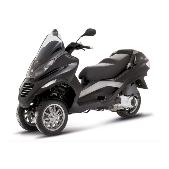
MP3 125 i.e. HYBRID
Ed. 2
Advertisement
Table of Contents

Related Manuals for PIAGGIO MP3 125 i.e. HYBRID


Summary of Contents for PIAGGIO MP3 125 i.e. HYBRID
- Page 1 PIAGGIO WOULD LIKE TO THANK YOU for choosing one of its products. We have prepared this booklet to help you to get the very best from your scooter. Please read it carefully before riding the vehicle for the first time. It contains information, tips and precautions for using your vehicle. It also describes features, details and devices to assure you that you have made the right choice.
- Page 2 The instructions given in this booklet are intended to provide a clear, simple guide to using your scooter; this booklet also details routine maintenance procedures and regular checks that should be carried out on the vehicle at an authorised Dealer or Service Centres. The booklet also contains instructions for simple repairs.
- Page 3 Personal safety Failure to completely observe these instructions will result in serious risk of personal injury. Safeguarding the environment Sections marked with this symbol indicate the correct use of the vehicle to prevent dam- aging the environment. Vehicle intactness The incomplete or non-observance of these regulations leads to the risk of serious damage to the vehicle and sometimes even the invalidity of the guarantee.
-
Page 5: Table Of Contents
INDEX VEHICLE..................Riding mode................30 Dashboard................Recharge from the mains............34 Analogue instrument panel............10 Checks..................38 Clock..................12 Refuelling.................. 38 Digital lcd display..............13 Tyre pressure................40 Tasto TRIP................13 Shock absorbers adjustment............ 42 Key switch................. 14 Running in................. 43 Locking the steering wheel............ - Page 6 Front light group................ 76 Headlight adjustment............. 79 Front direction indicators............80 Rear optical unit................ 81 Number plate light..............82 Helmet compartment lighting bulb..........82 Rear-view mirrors..............83 Front and rear disc brake............83 Puncture..................84 Periods of inactivity..............85 Cleaning the vehicle..............86 TECHNICAL DATA..............
-
Page 7: Vehicle
MP3 125 i.e. HYBRID Chap. 01 Vehicle... -
Page 8: Dashboard
01_01 Dashboard (01_01) A = Ignition switch key... - Page 9 B = HYTECH push button C = Starter button D = Front suspension locking-unlocking switch E = Throttle grip F = Front brake lever G = Emergency cut-off switch RUN/OFF H = Digital instrument panel I = Analogue instrument panel L = High-low beam switch M = Rear brake lever N = Turn indicator switch...
-
Page 10: Analogue Instrument Panel
01_02 Analogue instrument panel (01_02) A = Immobilizer / anti-theft LED B= Speedometer with twin scale (km/h and mph) - Page 11 C = CLOCK switch D = Digital display E= SET switch F = Traction battery charge status indicator G = Fuel gauge H = Warning light for helmet compartment courtesy light on I = Hybrid engine control and failure warning light L = Low fuel warning light M = Engine stop warning light N= Turn indicator warning light...
-
Page 12: Clock
Clock (01_03) Pushing the «CLOCK» button for less than 1 second displays the following sequence: • TIME • DATE To set the clock, push and hold the «CLOCK» button for other 3 seconds. The numbers showing the hours will begin flashing. Set the hour using the «SET»... -
Page 13: Digital Lcd Display
Digital lcd display (01_04) A = Total odometer gauge B = Trip odometer gauge (A-B) C = Riding mode indicator D = Temperature indicator: cooling liquid in the hybrid modes - electric traction and batteries in the electric mode E = TIME-DATE indicator 01_04 F = Recharge plug indicator out of its housing G = In reverse mode indicator (electric only) -
Page 14: Key Switch
Key switch (01_06) 1. LOCK = Ignition disabled, extractable key, mechanical antitheft device ena- bled. The parking brake cannot be released when pressed and cannot be pressed when released. 2. « OFF » = Ignition disabled, extractable key, mechanical antitheft device dis- abled and enabled/disabled parking brake. -
Page 15: Switch Direction Indicators
CAUTION DO NOT TURN THE KEY TO «LOCK» OR «KEY OFF» WHILE RIDING. Switch direction indicators (01_08) Move switch «F» to the left to indicate a left turn; move switch «F» to the right to indicate a right turn. Push the central part of switch «F» to deactivate the turn indica- tors. -
Page 16: Light Switch
Light switch (01_10) When the light switch «H» is set to «0», the low-beam light is on. When set to «1», the high-beam light is activated. If the light switch «H» is pressed when set to «2», the high-beam light flashing is activated. The switch goes back to «0» automatically. 01_10 Emergency flashing light button (01_11) It enables the activation of the four turn indicators simultaneously. -
Page 17: Start-Up Button
Start-up button (01_12) To start the engine, pull either brake lever and then press the starter button «R». WARNING THE VEHICLE WILL START BUT WILL IDLE IF THE RIDER IS NOT SEATED ON THE SADDLE IN RIDING POSITION. 01_12 Engine stop button (01_13) The engine can be started when the emergency stop switch «N»... -
Page 18: Front Suspension Unlock-Lock Switch
Front suspension unlock-lock switch (01_14) The «Q» switch engages and disengages the front suspension locking system. As the topic is so complex, find the instructions for using this control in the Use chapter. 01_14 courtesy horn (01_15) Press the "B" button to sound the courtesy horn. 01_15... -
Page 19: Hy Tech Button
01_16 The immobilizer system In order to enhance theft protection, the vehicle is equipped with a «PIAGGIO IMMO- BILIZER » electronic engine locking device that is activated automatically when the ignition key is removed. Upon start-up, the «PIAGGIO IMMOBILIZER» system checks the starter key, and only if this key is recognised will the Immobilizer system allow the vehicle to be started. -
Page 20: Immobilizerdevice Enabled Indicator Led
01_19 Immobilizerdevice enabled indicator led (01_20) Activation of the "PIAGGIO IMMOBILIZER" system is signalled by a flashing «A» indicator. In order to reduce battery discharge, the indicator LED turns off automatically after 48 hours of uninterrupted functioning. Should the system fail, different LED flash- ing patterns will provide the Authorised Service Centre with information on the type of fault detected. -
Page 21: Operation
Operation Each time the starter key «B» is removed while in the «OFF» or «LOCK» positions, the protection system activates the engine lock. Turning the starter key «B» to «ON» disables the engine lock, provided that the safety system recognises the code trans- mitted by the key. -
Page 22: Programming The Immobilizer System
Programming the immobilizer system (01_21) Below is described the procedure to follow for programming the PIAGGIO IMMOBIL- IZER system and/or for storing other key codes. The programming procedure should be carried out with the engine stop switch set to «RUN». -
Page 23: Accessing The Fuel Tank
CORRECT PROGRAMMING CHECK PHASE Insert the «MASTER» key «A» disabling the transponder «C» (i.e., by tilting the key cap by 90°), and turn the key to «ON». Perform the engine start-up operation. Ensure that the engine does not start. Insert the programmed key «B» and repeat the start- up operation. -
Page 24: Power Supply Socket
Power supply socket (01_23) There is a plug socket «D» inside the rear case. The plug socket may be used for external consumers (mobile phone, inspection light, etc.). CAUTION 01_23 PROLONGED USE OF THE PLUG SOCKET MAY RESULT IN PARTIAL DIS- CHARGE OF THE BATTERY Electric characteristic Plug socket... -
Page 25: Opening The Saddle
01_25 01_26 Opening the saddle (01_27) When the key is set to «ON» or «OFF», the saddle can be opened by pressing button «T». The saddle cannot be opened when the key is set to «LOCK». 01_27... -
Page 26: Opening The Saddle To Access The Helmet Compartment In An Emergency
Opening the saddle to access the helmet compartment in an emergency (01_28, 01_29) If the remote control battery or the vehicle battery is discharged, follow these steps to open the saddle: 1. Open the rear compartment with the key switch 2. -
Page 27: Identification
TURNING OFF. IN ANY CASE, THE WARNING LIGHT "H" ON THE INSTRUMENT PANEL SIGNALS IF THE LIGHT IS ON OR OFF. Identification (01_31, 01_32) Identification registration numbers are made up of a prefix and a number, stamped on the chassis and on the engine. These numbers must always be quoted when ordering spare parts. -
Page 28: Bag Clip
Engine number The engine number «B» is stamped near the rear left shock absorber lower support. 01_32 Bag clip (01_33) To use the retractable bag hook «B» mounted on the leg shield back plate, pull it slightly towards the back of the vehicle. 01_33... -
Page 29: Use
MP3 125 i.e. HYBRID Chap. 02... -
Page 30: Riding Mode
Riding mode (02_01, 02_02, 02_03, 02_04, 02_05, 02_06, 02_07, 02_08) The vehicle is equipped with two powerplants that work in parallel: a petrol engine and an electric motor powered by a specific traction battery. Thus configured, the engine and motor are both able to supply power to the wheel and give the possibility of choosing various functioning modes: hybrid or electric. - Page 31 It is possible to select the operating mode with the HY TECH key located on the right- hand push button panel of the handlebar. When this key is pressed the four operating modes are displayed. While scrolling the menu looking for the desired mode the indi- cation on the instrument panel is flashing;...
- Page 32 02_03 02_04 Repeat the steps to go over to the electric mode only. The word ELECTRIC appears on the display as shown in the figure. The instrument "A" gives the traction battery charge status. The moment you turn the acceleration knob suspension is released. You can now proceed at a maximum speed of 30 Km/h.
- Page 33 02_06 To facilitate small parking manoeuvres, the vehicle has the reverse gear which can only be activated in the ELECTRIC mode. To activate the reverse gear, press the HY TECH button as described previously until the icon shown in the photo turns on. Re- verse gear may only be selected when the vehicle is at a standstill.
-
Page 34: Recharge From The Mains
The power cable is fitted with a fused device "C". CAUTION 02_09 DO NOT, UNDER ANY CIRCUMSTANCES, REMOVE THE COVER FROM THE BATTERY COMPARTMENT. CONTACT AUTHORISED PIAGGIO ASSISTANCE CENTRES ONLY. RECHARGE THE BATTERIES IN A VENTILATED AREA, FAR AWAY FROM SOURCES OF HEAT, NAKED FLAMES OR SPARKS. - Page 35 IF THE VEHICLE IS NOT GOING TO BE USED FOR A LONG TIME, RECHARGE THE BATTERIES COMPLETELY AT LEAST EVERY 3 (THREE) MONTHS TO RECHARGE THE BATTERIES PLUG INTO A PUBLIC CHARGING STATION FOR ELECTRIC VEHICLES OR A HOUSEHOLD SOCKET CONFORMING TO STANDARDS, EARTHED AND FITTED WITH AN RCD.
- Page 36 02_13 With the ignition key "ON" take the recharge plug out of its place, the icon "B" is displayed, shown in the figure. Turn the key to "OFF", close the saddle making sure to correctly place the recharge cable introducing the pin in the electric mains socket, the recharge procedure starts. While it is recharging the recharging device cooling fan turns on and the warning light "A"...
- Page 37 02_16 If the NO COM icon turns on on the display, position the ignition key "OFF" and then position it back "ON". If the problem persists, contact an Authorised Service Cen- tre to verify causes and to restore correct operation. 02_17 Press the "B"...
-
Page 38: Checks
Checks Before using the vehicle, check: 1. That the fuel tank is full. 2. The correct fluid level for front and rear brakes. 3. That the tyres are properly inflated. 4. The correct functioning of side lights, headlamp, turn indicators, stop light and li- cense plate light. - Page 39 DO NOT ALLOW PETROL TO COME INTO CONTACT WITH HOT ENGINE OR ANY PLASTIC PARTS. CAUTION PETROL DAMAGES THE PLASTIC PARTS OF THE BODYWORK. WARNING 02_20 DO NOT RIDE WITH THE FUEL TANK ALMOST EMPTY, LACK OF FUEL CAN DAMAGE THE CATALYTIC CONVERTER. CAUTION USING NON-RECOMMENDED PETROL REDUCES THE EFFICIENCY OF THE EXHAUST AND FUEL SUPPLY SYSTEMS.
-
Page 40: Tyre Pressure
WARNING IT IS HIGHLY INADVISABLE TO REFUEL USING METHODS OTHER THAN NOR- MAL FUEL PUMPS. IF PETROL IS NOT COMPLETELY CLEAN, IT CAN DAMAGE THE FUEL SUPPLY SYSTEM FILTERS. CAUTION USING OILS OTHER THAN THOSE RECOMMENDED CAN SHORTEN THE LIFE OF THE ENGINE. - Page 41 CAUTION TYRE PRESSURE SHOULD BE CHECKED WHEN TYRES ARE COLD.INCOR- RECT TYRE PRESSURE CAUSES ABNORMAL TYRE WEAR AND MAKES RID- ING DANGEROUS. TYRES MUST BE REPLACED WHEN THE TREAD REACHES THE WEAR LIMITS SET FORTH BY LAW. TYRE INFLATION PRESSURE Front tyre pressure 1.7 bar Rear tyre pressure (rider only)
-
Page 42: Shock Absorbers Adjustment
Shock absorbers adjustment (02_22, 02_23) The preloading of the springs can be adjusted to 4 positions acting on the ring nut located in the lower part of the shock absorbers with the specific spanner supplied. Position 1: minimum preload: rider only Position 2 medium preloading: rider only Position 3 medium preloading: rider and passenger Position 4: maximum preloading: rider, passenger, and luggage. -
Page 43: Running In
Running in (02_24) DURING THE FIRST 1000 KM DO NOT RIDE THE VEHICLE OVER 80% OF ITS MAX. SPEED. AVOID OPENING THE THROTTLE GRIP COMPLETELY OR KEEP- ING A CONSTANT SPEED ALONG LONG SECTIONS OF ROAD. AFTER THE FIRST 1000 KM INCREASE SPEED PROGRESSIVELY, IF POSSIBLE, UNTIL THE MAXIMUM PERFORMANCE IS OBTAINED. - Page 44 2. Keep the throttle «P» completely untwisted. 3. Insert the key into the ignition switch «A» and turn it to «ON». 4. Make sure that switch «N» is set to «ON». 5. Pull either the front «O» or rear «G» brake lever and afterwards press the starter button «R».
-
Page 45: Precautions
CAUTION DO NOT SHUT OFF THE ENGINE WHILE THE VEHICLE IS MOVING. UNBURNED FUEL COULD ENTER THE CATALYTIC CONVERTER AND BURN, CAUSING THE CONVERTER TO OVERHEAT AND POSSIBLY DESTROYING IT. CAUTION DO NOT PUSH THE STARTER BUTTON OR TURN THE KEY SWITCH TO «ON» WHEN THE TANK IS EMPTY BECAUSE IT COULD DAMAGE THE START-UP SYSTEM. -
Page 46: Stopping The Engine
OVERREVVING, THE REVOLUTION LIMITER WILL BE ACTIVATED IF THE EN- GINE SPEED EXCEEDS THE ESTABLISHED THRESHOLD. WARNING AFTER A LONG DISTANCE COVERED AT THE MAXIMUM SPEED, DO NOT STOP THE ENGINE IMMEDIATELY, BUT LET IT RUN AT IDLE FOR A FEW SECONDS. CAUTION THIS VEHICLE IS FITTED WITH A SAFETY SYSTEM: IF THERE IS A FAILURE THAT COMPROMISES THE SAFETY OF BOTH RIDER AND VEHICLE, THE SYS-... -
Page 47: Stand
CAUTION DO NOT SHUT OFF THE ENGINE WHILE THE VEHICLE IS MOVING. UNBURNED FUEL COULD ENTER THE CATALYTIC CONVERTER AND BURN, CAUSING THE CONVERTER TO OVERHEAT AND POSSIBLY DESTROYING IT. Stand (02_29) CENTRE STAND Push with your foot on the centre stand's fork «F» while lifting the vehicle backward, holding onto the handlebar. -
Page 48: Safe Driving
those previously indicated) like driving up a steep hill fully loaded or starting off with rider and passenger on a slope with a gradient greater than 25%. Take the following precautions if the clutch overheats: 1.Do not continue riding in such conditions. 2. - Page 49 CAUTION ALWAYS RIDE WITHIN YOUR LIMITS RIDING UNDER THE INFLUENCE OF AL- COHOL OR OTHER DRUGS AND CERTAIN MEDICINES IS EXTREMELY DAN- GEROUS. CAUTION IN ORDER TO PREVENT ANY ACCIDENTS RIDE VERY CAREFULLY AFTER ADDING ACCESSORIES AND WHILE CARRYING LUGGAGE. ADDING ACCES- SORIES AND LUGGAGE CAN REDUCE THE VEHICLE'S STABILITY, PERFORM- ANCE AND SAFETY DURING USE.
-
Page 50: Front Suspension Locking System
Front suspension locking system (02_31, 02_32, 02_33, 02_34, 02_35, 02_36, 02_37) The front suspension locking system simply prevents vehicle tilting when the «T » switch is pressed. The vehicle can be stopped without your feet touching the ground. The warning light «E» starts flashing when the ignition key is set to «ON». This means that the system is enabled for locking activation. - Page 51 "T" by hand into position "2". In forward gear, suspension locks automatically when the throttle is turned. You can now proceed at a maximum speed of 30 Km/h. If there is a double start-off (pilot and passenger) with Roll Lock engaged and electric motor, it is advisable to keep your feet on the ground so as to increase operation safety.
- Page 52 WARNING EVERY TIME THE VEHICLE IS STOPPED, MAKE SURE THE FRONT SUSPEN- SION LOCKING SYSTEM IS ENGAGED. OTHERWISE, PLACE YOUR FEET ON THE GROUND TO KEEP THE VEHICLE UPRIGHT. WARNING AVOID USING THE LOCKING SYSTEM WHEN RIDING THE VEHICLE ALONG IR- REGULAR ROADS OR ROADS WITH OBSTACLES (E.G.
- Page 53 With the vehicle off and the suspension locking system engaged, it is possible to get off the vehicle without using the stand. For safety reasons, it is recommended to press the hand brake lever shown in the figure, moving it form position «A » to position «B».
-
Page 54: Parking Brake
If the WARNING light «Q » turns on (flashes), it means that there is a failure in the front suspension locking system. Therefore, it is necessary to contact an Authorised Service Centre. If the front suspension is locked, it can be unlocked by operating the «T»... - Page 55 IT IS IMPOSSIBLE FOR THE VEHICLE TO MOVE, RISKING AN ACCIDENTAL FALL.
-
Page 57: Maintenance
MP3 125 i.e. HYBRID Chap. 03 Maintenance... -
Page 58: Engine Oil Level
Engine oil level In 4T engines, engine oil is used to lubricate the timing system elements, main bear- ings and thermal group. An insufficient quantity of oil can seriously damage the engine. In all four-stroke engines, a loss of efficiency in oil performance and certain consumption should be considered normal. -
Page 59: Engine Oil Top-Up
03_02 Engine oil top-up Always check the oil level before topping up, and add oil without exceeding the MAX level. Getting an oil level between the MIN and MAX levels requires ~ 200 cm³ of oil. Take your vehicle to an Authorised Service Centre to have the oil checked and if necessary, topped-up as indicated in the scheduled maintenance table. -
Page 60: Engine Oil Change
Engine oil change (03_03) Have oil changed and the cartridge filter «C» replaced as indicated in the scheduled maintenance table at an Authorised Service Centre. The engine should be emptied by draining the oil through drainage plug «B » of the mesh filter on the flywheel side. In order to facilitate the oil drainage, loosen the cap/dipstick. -
Page 61: Hub Oil Level
CAUTION USING OILS OTHER THAN THOSE RECOMMENDED CAN SHORTEN THE LIFE OF THE ENGINE. Recommended products AGIP CITY HI TEC 4T Engine oil SAE 5W-40, API SL, ACEA A3, JASO MA Synthetic oil Hub oil level (03_04, 03_05) Check the oil in the rear hub. To check the rear hub oil level, proceed as follows: 1. - Page 62 CAUTION RIDING THE VEHICLE HUB WITH INSUFFICIENT HUB LUBRICATION OR WITH CONTAMINATED OR IMPROPER LUBRICANTS ACCELERATES THE WEAR AND TEAR OF THE MOVING PARTS AND CAN CAUSE SERIOUS DAMAGE. CAUTION 03_05 USED OIL CAN HARM THE ENVIRONMENT. COLLECTION AND DISPOSAL SHOULD BE CARRIED OUT IN COMPLIANCE WITH REGULATIONS IN FORCE.
-
Page 63: Tyres
Recommended products AGIP ROTRA 80W-90 Rear hub oil SAE 80W/90 Oil that exceeds the requirements of API GL3 specifications Characteristic Transmission oil 250 cm³ Tyres (03_06) Check tyre pressure and wear periodically (roughly every 500 km). Tyres feature wear indicators; replace tyres as soon as these indicators become visible on the tyre tread. Also check that the tyres do not show signs of splitting at the sides or irregular tread wear;... - Page 64 WARNING THE WHEELS FITTED WITH TYRES SHOULD ALWAYS BE BALANCED. RIDING THE VEHICLE WITH VERY LOW TYRE PRESSURE OR WITH INCORRECTLY BALANCED TYRES CAN LEAD TO DANGEROUS STEERING VIBRATIONS. TYRE INFLATION PRESSURE Front tyre pressure 1.7 bar Rear tyre pressure (rider only) 2.4 bar Rear wheel pressure (rider and 2.8 bar...
-
Page 65: Spark Plug Dismantlement
Spark plug dismantlement (03_07, 03_08) Proceed as follows: 1.Remove the access cover over the spark plug on the right-hand side of the scooter, reach the spark plug and slide it off with your hand; 2.Disconnect spark plug HV wire cap «A»; 3. -
Page 66: Removing The Air Filter
NGK CR8EB Electrode gap 0.7 to 0.8 mm Removing the air filter (03_09) Proceed as follows: Undo the clamping screws «A» (two of which are on the knob-type head) and remove the air-box cover. 03_09 Air filter cleaning 1. Wash the sponge with water and mild soap. 2. -
Page 67: Cvt Filter Removal
Recommended products AGIP FILTER OIL Oil for air filter sponge Mineral oil with specific additives for increased adhesiveness CVT filter removal (03_10, 03_11) • Undo the 4 screws "A" and remove the transmission house filter cover "B" • Extract the filter element "C" from the cover 03_10 03_11... -
Page 68: Cvt Filter Cleaning
CVT filter cleaning (03_12) 1. Wash the sponge with water and mild soap. 2. Dry it with a clean cloth and short blasts of compressed air. CAUTION IF THE VEHICLE IS USED ON DUSTY ROADS SERVICE THE CVT FILTER MORE 03_12 OFTEN TO AVOID DAMAGING THE ENGINE. - Page 69 If it is necessary to top-up the coolant frequently, or if the expansion tank is completely dry, you should look for the cause in the cooling system. It is therefore essential to have the cooling system checked at an Authorised Service Centre. Replace coolant as indicated in the scheduled maintenance table.
-
Page 70: Checking The Brake Oil Level
Checking the brake oil level (03_17) The front and rear brake fluid reservoirs are both positioned on the handlebar. Proceed as follows: 1. Rest the vehicle on its centre stand with the handlebars perfectly horizontal; 2. Check the liquid through the sight glass «C». A certain lowering of the level is caused by wear on the brake pads. -
Page 71: Battery
CAUTION AVOID CONTACT OF BRAKE FLUID WITH EYES, SKIN, AND CLOTHING. IN CASE OF CONTACT, RINSE WITH WATER. THE BRAKING CIRCUIT FLUID IS HYGROSCOPIC, THAT IS, IT ABSORBS HUMIDITY FROM THE SURROUNDING AIR. IF THE HUMIDITY IN THE BRAKING FLUID EXCEEDS A CERTAIN VALUE, IT WILL LEAD TO INEFFICIENT BRAKING. -
Page 72: Fuses
Fuses (03_19, 03_20, 03_21) The electrical system has twelve fuses to protect the different installation circuits divi- ded in two fuse boxes. One of them is inside the rear case and the other is inside the footrest on the right hand. To be able to reach them, loosen the screw "A" and remove the plastic cover. - Page 73 USE TABLE Fuses No. 1 - Current rating: 30 A Protected circuits: battery recharge circuit, traction battery control device. Fuses No. 2 - Current rating: 20A Protected circuits: Fuse No. 7. Live:fuses no. 9,10,11 and 12. Fuses No. 3 - Current rating: 20A Protected circuits: electronic...
- Page 74 electronic ignition device, immobiliser antenna, engine stop switch. Fuses No. 11 - Current rating: 7.5A Protected circuits: instrument panel, suspension locking device, horn solenoid, front headlight solenoid, anti-theft installation. Fuses No. 12 - Current rating: 7.5A Protected circuits: Daylight running lights, panel lighting,...
- Page 75 Quantity: 1 Rear turn indicator light bulb Type: Incandescent (W2.1 x 9.5D) Power: 12V - 5W Quantity: 2 RHS + 2 LHS Rear tail light bulb Type: Incandescent (W2.1 x 9.5D) Power: 12V - 5W Quantity: 1 RHS + 1 LHS Stop light bulb Type: Incandescent (BAU 15s) Power: 12V - 10W...
-
Page 76: Front Light Group
Front light group (03_22, 03_23, 03_24, 03_25, 03_26, 03_27, 03_28, 03_29, 03_30) To remove the front headlight assembly, proceed as follows: 1. Remove the Piaggio clip-on badge 2. Remove the screw «A» and the headlight assembly central cover 3. Remove the two headlamp upper fixing screws «B»... - Page 77 03_24 03_25 03_26...
- Page 78 03_27 03_28 03_29...
-
Page 79: Headlight Adjustment
03_30 Headlight adjustment (03_31, 03_32) Proceed as follows: 1. Position the unloaded vehicle, in running order and with the tyres inflated to the prescribed pressure, onto a flat surface, 10 m away from a half-lit white screen; make sure the vehicle axis is perpendicular to the screen; 2. -
Page 80: Front Direction Indicators
Front direction indicators (03_33, 03_34) To remove the front turn indicator bulb, turn the bulb holder«A» anticlockwise and remove it from its fitting. 03_33 03_34... -
Page 81: Rear Optical Unit
Rear optical unit (03_35, 03_36, 03_37) To access the bulbs: - Open the rear case cover and undo the two screws «A». - Undo the four screws «B» and pull out the headlight assembly from its fitting. To replace the stop light bulbs «C», hold the bulb holder and turn it anticlockwise. Hold the bulb and at the same time push it and turn it anticlockwise. -
Page 82: Number Plate Light
Number plate light (03_38, 03_39) Open the rear case and remove the rubber «A» shown in the figure without damaging the plastic parts. Next, slide off the bulb holder. Remove the bulb afterwards. 03_38 03_39 Helmet compartment lighting bulb (03_40) Open the rear compartment and insert a small plain slot screwdriver in the lateral notch to detach the snap-on glass «D», then replace the bulb. -
Page 83: Rear-View Mirrors
Rear-view mirrors (03_41) The mirrors can be set to the desired position by adjusting the mirror frame. 03_41 Front and rear disc brake The brake disc and pad wear is automatically compensated, therefore it has no effect on the functioning of the front and rear brakes. For this reason it is not necessary to adjust the brakes. -
Page 84: Puncture
ING SYSTEM DURING OPERATION, IT IS ADVISABLE TO HAVE THE BRAKING SYSTEM CHECKED BY AN AUTHORISED SERVICE CENTRE OR DEALER. AF- TER REPLACING THE BRAKE PADS, DO NOT USE THE SCOOTER UNTIL YOU HAVE OPERATED THE BRAKE LEVER SEVERAL TIMES IN ORDER TO ALLOW THE PLUNGERS TO SETTLE AND THE LEVER STROKE TO BE SET TO THE CORRECT POSITION. -
Page 85: Periods Of Inactivity
WARNING THE WHEELS FITTED WITH TYRES SHOULD ALWAYS BE BALANCED. RIDING THE VEHICLE WITH VERY LOW TYRE PRESSURE OR WITH INCORRECTLY BALANCED TYRES CAN LEAD TO DANGEROUS STEERING VIBRATIONS. Periods of inactivity We recommend carrying out the following operations: 1. Clean the scooter thoroughly and then cover it with a canvas; 2. -
Page 86: Cleaning The Vehicle
Oil for 4-stroke engines Cleaning the vehicle (03_42) Use a low pressure jet of water to soften the caked dirt and mud deposited on the painted surfaces. Once softened, sponge off mud and dirt using a car body sponge soaked in a car body shampoo and water solution (2-4% of car shampoo in water). Then rinse with abundant water, and dry with a shammy cloth. - Page 87 • DO NOT USE WATER AT TEMPERATURES OVER 40ºC. • DO NOT USE HIGH-PRESSURE WATER JETS. • DO NOT STEAM WASH. • DO NOT AIM THE JET AT: THE WIRING AND COOLING SLITS ON THE TRANS- MISSION COVER. CAUTION NEVER WASH THE SCOOTER IN DIRECT SUNLIGHT, ESPECIALLY IN SUMMER WHEN THE BODYWORK IS STILL HOT AS THE SHAMPOO COULD DAMAGE THE PAINTWORK IF IT DRIES BEFORE BEING RINSED OFF.
- Page 88 GNITION PROBLEMS Faulty spark plug Contact an Authorised Service Centre. Faulty ignition / injection control Contact an Authorised Service unit. Centre. Faulty coil. Due to the presence of Contact an Authorised Service high voltage, this check should Centre. only be carried out by an expert. ACK OF COMPRESSION Loose spark plug.
- Page 89 INSUFFICIENT BRAKING Greasy disc. Worn pads. Faulty Contact an Authorised Service braking system. Presence of air in Centre. the front and rear brake circuit. INEFFICIENT SUSPENSION Shock absorber fault, oil leak, end Contact an Authorised Service buffers damaged; shock absorber Centre.
-
Page 91: Technical Data
MP3 125 i.e. HYBRID Chap. 04 Technical data... - Page 92 04_01...
- Page 93 HYBRID POWERTRAIN DATA Type Single-cylinder, 4-stroke Engine capacity 124 cm³ Bore x stroke 57 x 48.6 mm Compression ratio 12±0.5 : 1 Engine idle speed 1600 ± 100 rpm. Timing system 4 valves, single overhead camshaft, chain-driven. Valve clearance Intake: 0.10 mm Exhaust: 0.15 mm Max.
- Page 94 Ignition Electronic inductive discharge ignition, high efficiency, with separate HV coil. α/N three-dimensional map Ignition advance managed by control unit Spark plug NGK CR8EB Fuel system ELDOR KUBO02 electronic injection with throttle body ø 32mm and electric fuel pump. Fuel Unleaded petrol (95 RON) Exhaust silencer Absorption-type exhaust silencer...
- Page 95 VEHICLE TECHNICAL DATA Chassis Tubular and sheet steel Front suspension The roll system is composed of an articulated parallelogram suspension with die-cast aluminium control arms and two side headstocks plus shock absorbers with hydraulic locking system. Rear suspension Two double-acting shock absorbers, adjustable to four positions at preloading.
-
Page 96: Kit Equipment
Kerb weight 251 ± 10 kg Maximum weight allowed 445 kg Service battery 12 V12Ah SEALED BATTERY Traction battery 37V - 31Ah LITHIUM ION battery CAPACITY Engine oil Capacity: 1.3 l (dry); 1.2 l (when changing oil and filter) Transmission oil 250 cm³... -
Page 97: Spare Parts And Accessories
MP3 125 i.e. HYBRID Chap. 05 Spare parts and accessories... -
Page 98: Warnings
FITTED WITH ACCESSORIES OR WITH UNUSUAL LOADS. WARNING IT IS ALSO RECOMMENDED THAT ORIGINAL PIAGGIO SPARE PARTS BE USED, AS THESE ARE THE ONLY ONES OFFERING YOU THE SAME QUALITY GUARANTEE AS THOSE INITIALLY FITTED ON THE SCOOTER. THE USE OF NON-ORIGINAL SPARE PARTS RENDERS THE WARRANTY VOID. - Page 99 THE SCOOTER CAN BE RIDDEN AT A HIGHER SPEED WITHOUT THE ACCES- SORIES MENTIONED BEFORE WITHIN THE LIMITS ESTABLISHED BY LAW. IF THERE ARE ANY NON-PIAGGIO ACCESSORIES INSTALLED, OR AN AB- NORMAL LOAD, OR IF THE SCOOTER IS NOT IN A GENERALLY GOOD CON- DITION, OR WHENEVER WEATHER CONDITIONS DEMAND IT, SPEED SHOULD BE FURTHER REDUCED.
-
Page 101: Programmed Maintenance
MP3 125 i.e. HYBRID Chap. 06 Programmed maintenance... -
Page 102: Scheduled Maintenance Table
Scheduled maintenance table (06_01) Adequate maintenance is fundamental to ensure long-lasting, optimum operation and performance of your vehicle. To this end, a series of checks and maintenance operations (at the owner's expense) have been suggested, which are included in the summary table on the following page. Any minor faults should be reported without delay to an Authorised Service Centre or Dealer without waiting until the next scheduled service to solve it. - Page 103 Km x 1,000 Brake levers Brake fluid * Coolant * Engine oil Hub oil Headlight aiming adjustment Brake pads Sliding shoes / CVT rollers Tyre pressure and wear Vehicle road test Radiator (external cleaning) Suspension Steering Roll lock gripper control cable Transmission I: CHECK AND CLEAN, ADJUST, LUBRICATE OR REPLACE IF NECESSARY.
- Page 104 CAUTION IF THE VEHICLE IS USED ON DUSTY ROADS, IT IS NECESSARY TO SERVICE THE AIR FILTER AND THE CVT FILTER MORE OFTEN TO AVOID DAMAGING THE ENGINE. RECOMMENDED PRODUCTS TABLE Product Description Specifications AGIP GEAR 80W-90 Oil for speed gearbox SAE 80W-90, API GL-4 mineral multigrade oil AGIP CITY HI TEC 4T Oil to lubricate flexible transmissions (throttle...
- Page 105 UNIT OF MEASURE - CONVERSION - E NGLISH YSTEM (IS). NTERNATIONAL YSTEM 1 Inch (in) 25.4 Millimetres (mm) 1 Foot (ft) 0.305 Meter (m) 1 Mile (mi) 1.609 Kilometre (km) 1 US Gallon (USgal) 3.785 Litre (l) 1 Pound (lb) 0.454 Kilogram (kg) 1 Cubic inch (in³) 16.4 Cubic centimetres (cm³)
- Page 106 06_02...
- Page 107 TABLE OF CONTENTS Spark plug: 65 Stand: 47 Air filter: 66 Fuel: 23 Light switch: 16 Start-up: 17 Fuses: 72 Suspension: 18, 50 Switch: 14–16, 18 Battery: 71 Maintenance: 57, 101, 102 Brake: 54, 70, 83 Headlight: 79 Mirrors: 83 Horn: 15, 18 Tank: 23 Hub oil: 61...
- Page 108 Not all versions/models shown in this publication are available in all countries. The availability of each model should be checked at the official Piaggio sales network. "© Copyright 2008 - PIAGGIO & C. S.p.A. Pontedera. All rights reserved. Reproduction of this publication in whole or in part is prohibited."...
Need help?
Do you have a question about the MP3 125 i.e. HYBRID and is the answer not in the manual?
Questions and answers