Table of Contents
Advertisement
Quick Links
INSTRUCTION MANUAL
Should you encounter a problem with your new
Please call customer service at: 1-855-803-9313.
READ ALL THESE INSTRUCTIONS AND SAVE THEM IN A SAFE PLACE FOR
WARNING: FOR OUTDOOR USE ONLY
DANGER
If you smell gas:
1.
Shut off gas to the appliance.
2.
Extinguish any open flame.
3.
Open lid.
If odour continues, keep away from
4.
the appliance and immediately call
your gas supplier or fire department.
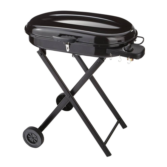
PORTABLE CART GAS GRILL
MODEL: 085-4090-8
STOP!
gas grill, CALL US FIRST!
Do not return the product to the store.
CONSUMER/USER
FUTURE REFERENCE.
WARNING
1.
Do not store or use gasoline or other
flammable liquids or vapours in the
vicinity of this or any other appliance.
An LP cylinder not connected for use
2.
must not be stored in the vicinity of this
or any other appliance.
1
Advertisement
Table of Contents

Subscribe to Our Youtube Channel
Related Manuals for Master Chef 085-4090-8


Summary of Contents for Master Chef 085-4090-8
- Page 1 PORTABLE CART GAS GRILL MODEL: 085-4090-8 INSTRUCTION MANUAL STOP! Should you encounter a problem with your new gas grill, CALL US FIRST! Do not return the product to the store. Please call customer service at: 1-855-803-9313. CONSUMER/USER READ ALL THESE INSTRUCTIONS AND SAVE THEM IN A SAFE PLACE FOR FUTURE REFERENCE.
-
Page 2: Table Of Contents
TABLE OF CONTENTS WARNINGS AND SAFETY‐INSTRUCTIONS .................. 3 EXPLODED DRAWING ........................ 4 ILLUSTRATED PARTS LIST & HARDWARE LIST ................... 5 ASSEMBLY INSTRUCTIONS ........................ 6 INSTALLATION .......................... 9 USER GUIDE ............................ 1 0 ASSEMBLY INSTRUCTIONS ...................... 1 1 LEAK TEST ............................ 1 2 FLASHBACK (FIRE IN BURNER TUBE) .................... 1 3 OPERATING YOUR GAS GRILL ...................... 1 3 MATCH LIGHTING ........................... 1 4 USING THE GAS GRILL ... -
Page 3: Warnings And Safety Instructions
Model No.: 085-4090-8 (BG065-1B) Type of Gas: Propane Total Input Rating: 15,000 BTU WARNINGS AND SAFETY INSTRUCTIONS If these instructions are ignored, there is a possibility of a hazardous fire or explosion which could result in physical injury or property damage! It is your responsibility to assemble, operate and maintain your gas grill properly. - Page 4 PREPARATION Before beginning assembly of product, make sure all parts are present. Compare parts with package contents list and diagram on page 5. If any part is missing or damaged, do not attempt to assemble the product. Please contact customer service for replacement parts at 1-855-803-9313.
- Page 5 Illustrated Parts Lists 3. Lower Tube Assembly 4. Short Leg 2. Wheel Tube Assembly Assembly 1 1. Wheel (REF# 3) 2PCS (REF# 1) (REF# 34) (REF# 4) 5. Short Leg Assembly 6. Middle Tube 7. Upper Tube Assembly Assembly 8. Grill Body Assembly 1PC (REF# 4) 1 PC (REF# 5) 1PC...
-
Page 6: Assembly Instructions
ASSEMBLY INSTRUCTIONS Step 1. Attach long leg (14) assembly to LH lower tube (3) assembly using bolt M6 X 35 (F). F. Bolt M6 x 35 (2PCS) Step 2. Attach short leg 1 (4) and short leg 2 (5) assembly to upper tube assembly (7) ,and wheel tube (2) assembly using bolt M6 X 35 (E) nd bolt M6 X 50 (F). - Page 7 ASSEMBLY INSTRUCTION Step 3. Attach long leg assembly (14) to short leg assembly (4 and 5) using leg bolts (J), leg spacers (I), and flat washer (C), lock washer (D) and Middle Tube Assembly (6). J. Leg Bolt (2PCS) I. Leg Spacer (2PCS) C.
- Page 8 ASSEMBLY INSTRUCTION Step 5. Attach long leg assembly (14) to grill bottom using leg bolts (L) and M6 lock nuts (B) and Heat resistant washer (O). When the legs are unfolded, the safety latch will automatically slide over the pin in the leg to prevent the grill from accidentally collapsing. Before folding the legs, lift the safety latch to allow the legs to fold.
- Page 9 ASSEMBLY INSTRUCTION Step 7. Attach lid handle (11), and cooking grid fix panel (9) using M6 x 16(A) with fibre washer between bolt head and lid. A. Bolt M6 x 16 with fibre washer (2PCS) Step 8. Install grease cup (13).
-
Page 10: Installation
4. Installation If these instructions are ignored, there is a possibility of a hazardous fire or explosion which could result in physical injury or property damage! It is your responsibility to assemble, operate and maintain your gas grill properly. 4.1 Choose a safe location. Once you have assembled your new gas grill, find a suitable location for use. -
Page 11: User Guide
WARNING: The outside of the gas grill body will become hot during use. To avoid burns, do not touch any hot gas grill surface. If necessary, use a protective glove when operating control knobs, tank shut-off valve or lid handle. Do not lean over gas grill or place hands or fingers on the hot parts of the gas grill. -
Page 12: Assembly Instructions
The regulator may make a humming or whistling noise during operation. This will not affect safety or use of grill. Save the cylinder cap and reinstall when not in use. Cylinder supply system must be arranged for vapour withdrawal. Do not block the pressure relief valve during use or storage. -
Page 13: Leak Test
WARNING: Connect the LP cylinder to the gas grill outdoors only. Read and follow all directions on the cylinder and fuel hose safety tags. 1. Check that the gas grill burner knob is turned to ”OFF”. 2. Remove the protective caps from the cylinder valve and coupling nut, if present. 3. -
Page 14: Flashback (Fire In Burner Tube)
5. Turn on the burner control knob for a moment to release pressure in hose, then turn the control knob back to off. 6. Wash off soapy solution with cold water and towel-dry. In case of a leak: Often tightening the joint will stop a leak. If necessary replace the faulty part with a replacement part recommended by the manufacturer. -
Page 15: Match Lighting
10.Match Lighting IMPORTANT! A match-lighting hole is located on the left side of the bottom bowl. To match-light: Push down and turn the burner control knob counter-clockwise to the high setting. IMMEDIATELY strike a long wooden match and position the burning match through the match-lighting hole in the gas grill bottom. -
Page 16: Care And Maintenance
Checking the burner flame: on right, a good flame; on left, a bad flame. If flames are excessively yellow and irregular, the oil residue may not be completely burnt off. After a gas grill has been in use for a while it may begin to have a more yellow flame. Check for clogged burner holes or blocked venturi tubes. -
Page 17: Warranty
12.2 Cleaning the venturi tube Spiders are very active in the late summer and fall just before frost. Unfortunately the venturi tube located on your gas grill burner can be an inviting home for them. This can be a serious problem if they build a home inside. A spider’s nest or wasp’s mud inside the venturi can block gas flow and can even cause a fire at the gas control valve. - Page 18 h) this warranty will not apply to normal deterioration of the exterior finish, such as, but not limited to, scratches, dents, paint chips, or to any corrosion or discoloring by heat, abrasive and chemical cleaners; and this warranty will not apply to component parts sold by and identified as the product of another company, which shall be covered under the product manufacturer’s warranty, if any.
Need help?
Do you have a question about the 085-4090-8 and is the answer not in the manual?
Questions and answers