Advertisement
Series 1996 Gas Pressure Switches
are designed for use with natural, man-
ufactured or LP gas or air.
Series 1996 Gas Pressure Switches
reliable and convenient switches for gas-fired furnaces
and equipment using natural, manufactured or LP gas.
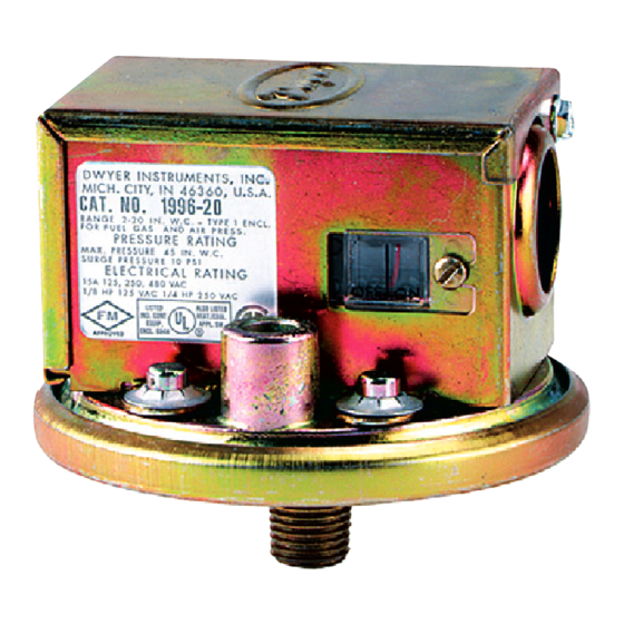
Both models (Model 1996-5, with a pressure range of 1.4
to 5.5" w.c.; Model 1996-20, with a pressure range of 4
to 20" w.c.) feature visible set point and on-off
indicators.
OPERATION
Pressure acting on the power diaphragm rotates the
amplifying lever, which in turn extends the range spring
and rotates the snap switch input lever. When the set
point is reached, the snap switch is actuated and the
electrical contacts make or break. Decreasing pressure
after the switch has been actuated reverses the action,
de-actuating the switch and returning the contacts to
their normal position.
INSTALLATION
1. Select a location free from excessive vibration and
corrosive atmosphere. These switches may be used in
ambient temperatures as low as - 30°F ( - 34°C) and as
high as 110°F (43°C).
2. Mount switch with diaphragm in a horizontal position
and gas pressure connection at bottom. Connect the
switch to the source of gas pressure using either the
NPT (F)8" or NPT (M) 4" thread. Gas pressure connec-
tion should always be to bottom connection of switch—
see diagram above—which is equipped with a restrictor
orifice.
Be sure to hold or turn switch with a wrench on
the hex portion of the bottom connection. This will pre-
vent applying excessive torque to the bottom fitting,
which could damage the switch.
DWYER INSTRUMENTS, INC.
P.O. BOX 373 • MICHIGAN CITY, INDIANA 46361, U.S.A.
Series 1996 – Natural and L.P. Gas Pressure Switches
Specifications - Installation and Operating Instructions
3-1/8
[79.38]
3-1/2
[88.90]
Connections, dimensions and visible
on-off indicator: Model 1996-20 and
Model 1996-5 Gas Pressure Switches.
are
Phone: 219/879-8000
Fax: 219/872-9057
Lit-By Fax: 888/891-4963
REMOVABLE CONDUIT
ENCLOSURE COVER
7/8 [22.23] OPENING FOR
1/2 [12.7] CONDUIT CONNECTION
WINDOW AND VISIBLE
ON-OFF INDICATOR
VENT CONNECTION
ON OPPOSITE SIDE
1/4 NPT EXTERNAL THREAD
(ALTERNATE GAS CONNECTION)
1/8 (F) GAS
PRESSURE CONNECTION
Note set point adjustment indicator win-
dow. For quick adjustment of set point
before/after installation, turn adjustment
screw until red bar is at desired set point.
To adjust for low gas pressure interlock
service, refer to chart (other side).
PHYSICAL DATA
Temperature limits: 32°F/0°C (- 30°F/- 34.4°C for dry gas or
air) to 110°F/ 43.3°C
8"
Pressure connection:
8"
Vent connection:
NPT
Electrical rating: 15 amps, 120-480 volts, 60 Hz. A.C.
8"
Resistive
H. P. @ 125 volts,
A.C.
Wiring connections: 3-screw type, Common, Normally Open
and Normally Closed
Set point adjustment: Screw type with visible indicator,
inside cabinet enclosure
On-off indicator: In window, on exterior of conduit enclosure.
Shows at a glance whether pressure is above or below set
and reset points.
Housing: Aluminum die casting and steel stamping,
zinc-plated for 200 hour salt spray resistance
Diaphragm: Molded Buna-N
Calibration spring: Stainless Steel
Weight: 1 lb, 2 oz
U.L. and C.S.A. listed, F.M. approved
The port identified with the letters LO-PR is used as a
vent in fuel gas switches and should be vented to
outside atmosphere or the combustion chamber in
accordance with the furnace manufacturer's
instructions. The port identified by the letters HI-PR is
not used in fuel gas switches and is neither tapped nor
connected to the diaphragm chamber.
WARNING:
Do not connect fuel gas to LO-PR port.
www.dwyer-inst.com
e-mail: info@dwyer-inst.com
Bulletin E-58
4"
NPT (F) or
NPT (M)
4"
H. P. @ 250 volts, 60 Hz.
Advertisement
Table of Contents

Related Manuals for Dwyer Instruments 1996 Series


Summary of Contents for Dwyer Instruments 1996 Series
- Page 1 This will pre- WARNING: vent applying excessive torque to the bottom fitting, Do not connect fuel gas to LO-PR port. which could damage the switch. DWYER INSTRUMENTS, INC. Phone: 219/879-8000 www.dwyer-inst.com P.O. BOX 373 • MICHIGAN CITY, INDIANA 46361, U.S.A. Fax: 219/872-9057 e-mail: info@dwyer-inst.com...
- Page 2 Burner Motorized Main Gas Gas Valves Gas Pressure Shut-Off Valve Regulator ©Copyright 2000 Dwyer Instruments, Inc. Printed in U.S.A. 6/00 FR # 26-440252-00 Rev. 1 DWYER INSTRUMENTS, INC. Phone: 219/879-8000 www.dwyer-inst.com P.O. BOX 373 • MICHIGAN CITY, INDIANA 46361, U.S.A.
Need help?
Do you have a question about the 1996 Series and is the answer not in the manual?
Questions and answers