
Related Manuals for HP PSR1800-56A


Summary of Contents for HP PSR1800-56A
- Page 1 HP PSR1800-56A Power Supply User Guide 5998-4302 Part number: 5998-4302 Document version: APW100-20130829...
- Page 2 The only warranties for HP products and services are set forth in the express warranty statements accompanying such products and services. Nothing herein should be construed as constituting an additional warranty.
-
Page 3: Table Of Contents
Connecting the AC power cord ·················································· 9 Removing the power supply······················································ 11 Support and other resources ································································ 14 Contacting HP ·················································································· 14 Subscription service ··································································· 14 Related information ········································································· 15 Documents ·················································································· 15 ... -
Page 4: Power Supply Overview
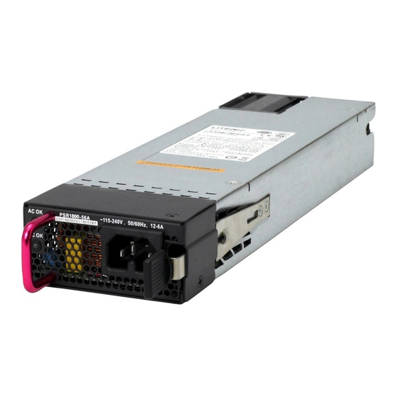
Power supply overview The PSR1800-56A (JG840A) is a power supply with AC input and DC output. It provides up to 1800 W output and delivers the following features: Feature Description Protection against over-current input, under-voltage input, over-voltage output, Protection over-current output, output short circuit, and over-temperature. - Page 5 Item Specifications 32.2 A (201 VAC to 240 VAC input • voltage) Output current 19.6 A (100 VAC to 200 VAC input • voltage) 1800 W (201 VAC to 240 VAC input • voltage) Maximum output power 1 100 W (100 VAC to 200 VAC input •...
-
Page 6: Appearance
(4) Handle (The handle is in red, indicating that the air ventilation is performed by exhausting air from the inside to the outside.) (5) Output status LED (DC OK) LEDs A PSR1800-56A has two status LEDs on its front panel. The following table lists the LED status and description. - Page 7 Status Description Steady green The power input is normal. Input status No power input or the power LED (AC OK) input is abnormal. Steady green The power output is normal. Output status LED Steady red The power output is abnormal. (DC OK) No power output.
-
Page 8: Installing And Removing A Power Supply
Installing and removing a power supply Safety precautions To avoid possible bodily injury and power supply and device damage, follow these safety precautions: When you install and remove a power supply, always wear an • ESD wrist strap and make sure it makes good skin contact and is well grounded. -
Page 9: Installing And Removing A Power Supply
Installing and removing a power supply IMPORTANT: Before installation, make sure the power supply model is as required. For more information about the device requirements, see the installation guide of the device. Installing the power supply To avoid bodily injury or device damage, follow the steps in Figure 2 install the power supply. - Page 10 To install the power supply: Put on the ESD wrist strap, making sure the strap makes good skin contact and is well grounded. Unpack the power supply and verify that the power supply model is as required. As shown in Figure 3, with the upside of the power supply up, hold the handle of the power supply with one hand and the bottom of...
- Page 11 Figure 4 Appearance of the power supply after installation IMPORTANT: To avoid damaging or bending the terminals of the power supply, • if the insertion direction is incorrect during the installation, you must pull the power supply out, adjust the direction, and insert it again.
-
Page 12: Connecting The Ac Power Cord
Figure 5 Removing the filler panel Connecting the AC power cord CAUTION: The PSR1800-56A power supply must use the high-temperature • resistant C15 connector power cord delivered with the power supply. Turn off the circuit breaker before connecting the power cord. - Page 13 To connect the power cord: As shown in Figure 6, plug the female connector end of the AC power cord into the AC input socket on the switch. Figure 6 Connecting the AC power cord As shown in Figure 7, use a cable tie to secure the power cord to the handle of the power supply.
-
Page 14: Removing The Power Supply
Plug the other end of the AC power cord into the socket strip of the power source, and turn on the circuit breaker of the power source. Examine the LED on the power supply. If the input status LED (AC OK) is steady green, the power cord is successfully connected. - Page 15 To remove the power supply: Turn off the circuit breaker of the power cord. Put on the ESD wrist strap, making sure the strap makes good skin contact and is well grounded. Loosen the cable tie, and remove the power cord. As shown in Figure 9, press the latch towards the handle, and pull...
- Page 16 Put the removed power supply on an antistatic mat or into its package. NOTE: If you do not insert another power supply into the slot after removing the power supply, install the filler panel to the power supply slot to prevent dust from entering the chassis.
-
Page 17: Support And Other Resources
Operating system type and revision level • Detailed questions • Subscription service HP recommends that you register your product at the Subscriber's Choice for Business website: http://www.hp.com/go/wwalerts After registering, you will receive email notification of product enhancements, new driver versions, firmware updates, and other... -
Page 18: Related Information
Related information Documents To find related documents, browse to the Manuals page of the HP Business Support Center website: http://www.hp.com/support/manuals For related documentation, navigate to the Networking section, • and select a networking category. For a complete list of acronyms and their definitions, see HP •... - Page 19 Command conventions Convention Description Bold text represents commands and keywords Boldface that you enter literally as shown. Italic text represents arguments that you Italic replace with actual values. Square brackets enclose syntax choices (keywords or arguments) that are optional. Braces enclose a set of required syntax { x | y | ...
- Page 20 GUI conventions Convention Description Window names, button names, field names, Boldface and menu items are in bold text. For example, the New User window appears; click OK. Multi-level menus are separated by angle > brackets. For example, File > Create > Folder. Symbols Convention Description...
- Page 21 Network topology icons Represents a generic network device, such as a router, switch, or firewall. Represents a routing-capable device, such as a router or Layer 3 switch. Represents a generic switch, such as a Layer 2 or Layer 3 switch, or a router that supports Layer 2 forwarding and other Layer 2 features.
Need help?
Do you have a question about the PSR1800-56A and is the answer not in the manual?
Questions and answers