
Related Manuals for Trane BCI-I


Summary of Contents for Trane BCI-I
- Page 1 Integration Guide BACnet™ Communication Interface (BCI-I) for IntelliPak™ and Commercial Self-contained ACC-SVP01B-EN September 2009...
- Page 2 © 2009 Trane All rights reserved This document and the information in it are the property of Trane and may not be used or reproduced in whole or in part, without the written permission of Trane. Trane reserves the right to revise this publication at any time and to make changes to its content without obligation to notify any person of such revision or change.
-
Page 4: Table Of Contents
............. . 45 ACC-SVP01B-EN • BCI-I Integration Guide... -
Page 5: Overview
“Additional Resources, ” p. BACnet Testing Laboratory (BTL) Certification The BCI-I supports the BACnet communication protocol and has been designed to meet the requirements of the application-specific control profile. For more details, refer to the BTL web site at www.bacnetassociation.org. -
Page 6: Bci-I Configuration
4. Click the Connect button and the Tracer TU main page will appear after successful connection. Note: The BCI-I may be powered via the USB cable or 24 Vac from the HVAC unit. Concurrent connection of unit power and the USB cable will not harm the BCI-I device. -
Page 7: Ip Units Configuration
Configuration. IP Units Configuration The BCI-I supports both inch-pound and SI (metric) units of measure. The factory default units of measure is SI. The device allows only a change of units for all objects as a whole. Mixed units of measure is not allowed. -
Page 8: Bacnet Object Configuration
6. Apply power to the HVAC equipment. Change Device ID By default, the BCI-I device sets its device ID to the same value as the one defined by the rotary switches (MS/TP MAC address) on the front of the device. Refer to the section, “Rotary Switches, ”... -
Page 9: Stand-Alone Or Bas Operation
The control system on HVAC equipment has the ability to operate the unit as a stand-alone system or as part of a building automation system. The BCI-I (either factory or field installed), by default, is configured for stand-alone operation. This configuration enables the HVAC equipment to operate prior to the commissioning of the unit into the BAS. -
Page 10: Periodic Update Of Bas Values
If the length of time exceeds a predefined limit, the BCI-I will place the object into the fault state and revert to a unit-supplied sensor value for control. At power up, the sensor objects are set to a fault state and they will remain in this state until a write is detected. -
Page 11: Diagnostics Reset Command
The BAS will change the state of the Filter Timer Reset Command object (BO 13) to the active state. Upon the change to active state, the BCI-I will set the present value of the Filter Runtime Hours object to zero and then set the Reset Command object back to the inactive state. -
Page 12: Timestamp Configuration
To minimize the possibility that the unit timestamp is not representing the actual time, the BAS should be setup to periodically synchronize the device time clock with the BAS clock using the BACnet TimeSynchronization service. ACC-SVP01B-EN • BCI-I Integration Guide... -
Page 13: Bci Intellipak Rotary Switches And Leds
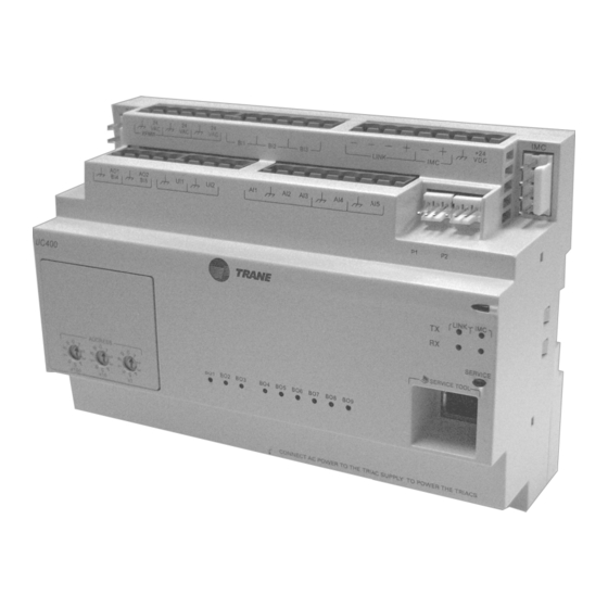
This section provides information about the BCI-I rotary switches and LED displays. Rotary Switches There are three rotary switches on the front of the BCI-I device that are used to define a three-digit address when the BCI-I is installed on a BACnet communications network. The three-digit address setting is the BACnet MAC address. -
Page 14: Leds Description, Behavior, And Troubleshooting
LEDs Description, Behavior, and Troubleshooting There are 15 LEDs on the front of the BCI-I unit. However, LEDs BO1 through BO9 are not used for the BCI-I controller. Figure 2 shows the locations of each LED. The following table provides a description of each LED activity, an indication or troubleshooting tips for each, and any notes. - Page 15 • Restore; using TU service tool will not run any applications such as trending, scheduling, and TGP2 Indicates controller is operating normally LED not lit runtime. Binary 01 to Binary 09 Not Used ACC-SVP01B-EN • BCI-I Integration Guide...
- Page 16 20.0 Vac ≤ V ≤ 30.0 Vac of-specification voltage, disconnect measurement while the unit is not the UC400 and measure the AC under load. voltage across the transformer. These measurements can direct the technician towards the problem source. ACC-SVP01B-EN • BCI-I Integration Guide...
- Page 17 Code™and local electrical codes) some route. that only one end of the shield conductor is tied to the earth ground Note: Do not assume that the building frame is a valid earth ground. ACC-SVP01B-EN • BCI-I Integration Guide...
-
Page 18: Bacnet Data Points And Configuration Property Definitions
Data Sharing-WriteProperty-B (DS-WP-B) Data Sharing-WritePropertyMultiple-B (DS-WPM-B) Alarm and Event Management Description Supported BIBB Alarm and Event-ACKI-B (AE-ACK-B) Alarm and Event-Alarm Summary-B (AE-ASUM-B) Alarm and Event-Enrollment Summary-B (AE-ESUM-B) Alarm and Event-Information-B (AE-INFO-B) Alarm and Event-Notification Internal-B (AE-N-I-B) ACC-SVP01B-EN • BCI-I Integration Guide... -
Page 19: Segmentation Capability
Device Management-Object Creation and Deletion-B (DM-OCD-B) Device Management-Private Transfer-A (DM-PT-A) Device Management-Private Transfer-B (DM-PT-B) Device Management-Reinitialize Device-B (DM-RD-B) Device Management-TimeSynchronization-B (DM-TS-B) Segmentation Capability Segmentation Description Supported Segment Segmented Requests/ Window Size: 1 Segmented Responses/ Window Size: 1 ACC-SVP01B-EN • BCI-I Integration Guide... -
Page 20: Object Types
• Polarity • Change_Of_State_Count • Time_Of_Active_Time_Reset • Elapsed_Active_Time • Time_Delay • Time_Delay • Notification_Class • Notification_Class • Alarm_Value • Alarm_Value • Event_Enable • Event_Enable • Acked_Transitions • Acked_Transitions • Notify_Type • Notify_Type • Event_Time_Stamps • Reliability ACC-SVP01B-EN • BCI-I Integration Guide... - Page 21 • Object_Name • Notify_Type user created Object • Object_Type • Event_Parameters objects • Event_Type • Object_Property_Reference • Notify_Type • Event_Enable • Event_Parameters • Notification_Class • Object_Property_Reference • Event_State • Event_Enable • Acked_Transitions • Notification_Class • Event_Time_Stamps ACC-SVP01B-EN • BCI-I Integration Guide...
- Page 22 • Log_Buffer • Last_Notify_Record • Event_State • Record_Count • Notification_Class • Notification_Threshold • Event_Enable • Notification_Class • Acked_Transitions • Event_Enable • Event_Time_Stamps • Notify_Type (a)Properties written for Present_Value and Reliability only if Out_of_Service is TRUE. ACC-SVP01B-EN • BCI-I Integration Guide...
-
Page 23: Bacnet Protocol
Device Address Binding Device Address Binding Supported? Static Device Binding Supported Networking Options Supported Networking Descriptions Option Annex H, BACnet Tunneling BACnet/IP Broadcast Management Device (BBMD) Does the BBMD Support Registrations by Foreign Devices? Router ACC-SVP01B-EN • BCI-I Integration Guide... - Page 24 Indicates support for multiple characters sets, but does not imply that all character sets are supported simultaneously. Maximum supported string length is 64 bytes (any character set). Character Set Descriptions Supported ANSI X3.4 IBM/Microsoft DBCS ISO 10646 (UCS-4) ISO 10646 (UCS2) ISO 8859-1 JIS C 6226 ACC-SVP01B-EN • BCI-I Integration Guide...
-
Page 25: Object Data Points And Diagnostic Data Points
Analog Output, 22 Discharge Air Dewpoint Setpoint BAS Degrees-Fahrenheit (64) 45.0 to 75.0 dewpoint setpoint value. BAS supplied discharge air Analog Output, 23 Discharge Air Reheat Setpoint BAS Degrees-Fahrenheit (64) 65.0 to 80.0 reheat setpoint value. ACC-SVP01B-EN • BCI-I Integration Guide... - Page 26 The mixed air temperature value from a unit-mounted Analog Input, 25 Mixed Air Temperature Degrees-Fahrenheit (64 sensor. The return air temperature value from a unit-mounted Analog Input, 26 Return Air Temperature Degrees-Fahrenheit (64 sensor. ACC-SVP01B-EN • BCI-I Integration Guide...
- Page 27 Indicates the active supply air reheat temperature Analog Input, 61 Discharge Air Reheat Setpoint Active Degrees-Fahrenheit (64) setpoint. Indicates the setpoint used during space humidification Analog Input, 62 Space Humidification Setpoint Active Percent (98) control. ACC-SVP01B-EN • BCI-I Integration Guide...
- Page 28 Table 5. Analog Value Object Identifier Object Name Description Units Valid Range The setpoint value used by the filter Analog Value, 1 Filter Runtime Hours Setpoint Hours (71) 0 to 10,000 run hours calculation. ACC-SVP01B-EN • BCI-I Integration Guide...
- Page 29 2= Mode A Active Indicates if the unit is in a ventilation 3= Mode B Active Multi-State Input, 13 Ventilation Override Status override mode of operation. 4= Mode C Active 5= Mode D Active 6= Mode E Active ACC-SVP01B-EN • BCI-I Integration Guide...
- Page 30 Heat Output 2 2 = On output 2. 3 = Not Present 1 = Off Indicates the commanded state of heating Multi-State Input, 31 Heat Output 3 2 = On output 3. 3 = Not Present ACC-SVP01B-EN • BCI-I Integration Guide...
- Page 31 Binary Output, 13 Filter Timer Reset Command Inactive accumulated filter run hours. Active = Reset Command the unit to reset and Inactive = Normal Binary Output, 14 Diagnostic Reset Command Inactive clear diagnostics. Active = Reset ACC-SVP01B-EN • BCI-I Integration Guide...
- Page 32 Diagnostic: RTM Aux Temp Sensor Failure Diagnostic: RTM Aux Temp Sensor Failure Identifier for RT or CSC) Binary Input, 31 (use Object Diagnostic: SA Temp Sensor Fail Diagnostic: SA Temp Sensor Fail Identifier for FAU) ACC-SVP01B-EN • BCI-I Integration Guide...
- Page 33 Diagnostic: SA Temp Heat Setpoint Fail Diagnostic: SA Temp Heat Setpoint Fail Binary Input, 76 Diagnostic: Dirty Filter Diagnostic: Dirty Filter Binary Input, 77 Diagnostic: NSB Zone Temp Sensor Fail Diagnostic: NSB Zone Temp Sensor Fail ACC-SVP01B-EN • BCI-I Integration Guide...
- Page 34 Diagnostic: SA Drying Setpoint Failure Diagnostic: SA Drying Setpoint Failure Identifier for FAU) Binary Input, 122 Diagnostic: Insufficient Airflow for Dehumid Diagnostic: Insufficient Airflow for Dehumid Binary Input, 123 Diagnostic: SA Reheat Setpoint Failure Diagnostic: SA Reheat Setpoint Failure ACC-SVP01B-EN • BCI-I Integration Guide...
- Page 35 Condenser water leaving temperature from a unit-mounted sensor. Binary Input, 24 Condenser Water Pump Status Indicates the status of the condenser water system pump. Analog Input, 42 Condensing Saturated Temperature Circuit 1 Indicates the saturated condenser temperature for circuit 1. ACC-SVP01B-EN • BCI-I Integration Guide...
- Page 36 The minimum position value the economizer damper will utilize. Analog Output, 1 Economizer Minimum Position Setpoint BAS BAS supplied economizer position minimum setpoint value. Analog Input, 86 Economizer Minimum Position Setpoint Local Indicates the local economizer minimum position setpoint. ACC-SVP01B-EN • BCI-I Integration Guide...
- Page 37 Heating Reset Type Status Indicates the type of heating reset. Multi-State Input, 23 Heating Setpoint Source Indicates the source of the space heating setpoint. Analog Input, 76 Humidification Capacity Status Indicates the unit humidification capacity being utilized. ACC-SVP01B-EN • BCI-I Integration Guide...
- Page 38 Indicates the low limit space CO setpoint for ventilation. Analog Output, 21 Space Dehumidification Setpoint BAS BAS supplied space dehumidification setpoint value. Analog Input, 17 Space Enthalpy The space enthalpy value from a unit-mounted control. ACC-SVP01B-EN • BCI-I Integration Guide...
- Page 39 Diagnostic: Auto - SA High Press Limit Diagnostic: Auto - SA High Press Limit 1 = active 0 = inactive BI 66 Diagnostic: BACnet Module Comm Fail Diagnostic: BACnet Module Comm Fail 1 = active ACC-SVP01B-EN • BCI-I Integration Guide...
- Page 40 Diagnostic: Ent Evap Temp Sensor Fail-Ckt 2 Diagnostic: Ent Evap Temp Sensor Fail-Ckt 2 1 = active 0 = inactive BI 109 Diagnostic: Ent Evap Temp Sensor Fail-Ckt 3 Diagnostic: Ent Evap Temp Sensor Fail-Ckt 3 1 = active ACC-SVP01B-EN • BCI-I Integration Guide...
- Page 41 1 = active 0 = inactive BI 62 Diagnostic: MCM Communications Failure Diagnostic: MCM Communications Failure 1 = active 0 = inactive BI 128 Diagnostic: MDM Communications Failure Diagnostic: MDM Communications Failure 1 = active ACC-SVP01B-EN • BCI-I Integration Guide...
- Page 42 BI 54 Diagnostic: SA Duct Press Setpoint Fail Diagnostic: SA Duct Press Setpoint Fail 1 = active 0 = inactive BI 123 Diagnostic: SA Reheat Setpoint Failure Diagnostic: SA Reheat Setpoint Failure 1 = active ACC-SVP01B-EN • BCI-I Integration Guide...
- Page 43 0 = inactive BI 80 Diagnostic: VOM Mode C Active Diagnostic: VOM Mode C Active 1 = active 0 = inactive BI 81 Diagnostic: VOM Mode D Active Diagnostic: VOM Mode D Active 1 = active ACC-SVP01B-EN • BCI-I Integration Guide...
- Page 44 Diagnostic: WSM MA Temp Sensor Failure 1 = active BI 58 0 = inactive (use Object Diagnostic: Zone Humidity Sensor Failure Diagnostic: Zone Humidity Sensor Failure 1 = active Identifier for FAU) (a) BI=Binary Input ACC-SVP01B-EN • BCI-I Integration Guide...
-
Page 45: Additional Resources
Tracer™ TU Service Tool Getting Started Guide (TTU-SVN02) (X39641083) • Tracer TU Service Tool for Water-cooled CenTraVac Chillers with Tracer AdaptiView Control Programming Guide (current version of CTV-SVP02) Note: For further assistance, contact your local Trane sales office. ACC-SVP01B-EN • BCI-I Integration Guide... -
Page 47: Glossary
See BACnet interoperability building blocks Building Automation Control network (BACnet and ANSI/ASHRAE Standard 135-2004) An interoperable protocol developed specifically for the building controls industry. The American National Standards Institute named it as a standard and Trane ACC-SVP01B-EN • BCI-I Integration Guide... - Page 48 September 2009 Supersedes ACC-SVP01A-EN www.trane.com For more information, contact your local Trane Trane has a policy of continuous product and product data improvement and reserves the right to office or e-mail us at comfort@trane.com change design and specifications without notice.
Need help?
Do you have a question about the BCI-I and is the answer not in the manual?
Questions and answers