Table of Contents
Advertisement
Quick Links
Installation Instructions
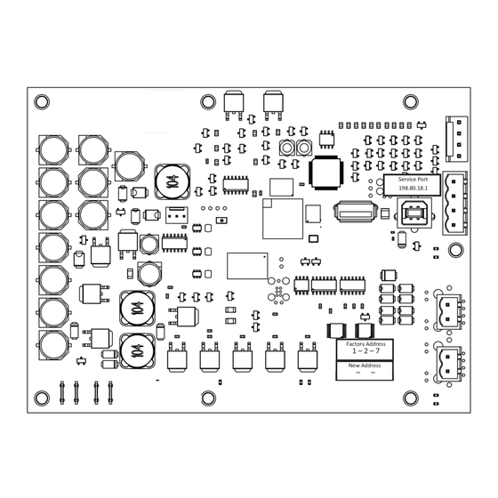
BACnet® Communication Interface
for Chillers (BCI2-C)
Field Kit Order Number KIT19852
Models:
RTWD, RTAC, CGAM
Only qualified personnel should install and service the equipment. The installation, starting up, and servicing of
heating, ventilating, and air-conditioning equipment can be hazardous and requires specific knowledge and training.
Improperly installed, adjusted or altered equipment by an unqualified person could result in death or serious injury.
When working on the equipment, observe all precautions in the literature and on the tags, stickers, and labels that are
attached to the equipment.
February 2024
SAFETY WARNING
RF-SVN006C-EN
Service Port
Service Port
Service Port
198.80.18.1
198.80.18.1
198.80.18.1
Factory Address
Factory Address
Factory Address
1 – 2 – 7
1 – 2 – 7
1 – 2 – 7
New Address
New Address
New Address
–
–
–
–
–
–
X39641444
Advertisement
Table of Contents

Related Manuals for Trane BACnet BCI2-C


Summary of Contents for Trane BACnet BCI2-C
- Page 1 Installation Instructions BACnet® Communication Interface for Chillers (BCI2-C) Field Kit Order Number KIT19852 Service Port Service Port Service Port 198.80.18.1 198.80.18.1 198.80.18.1 Factory Address Factory Address Factory Address 1 – 2 – 7 1 – 2 – 7 1 – 2 – 7 New Address New Address New Address...
- Page 2 When working with or around hazardous chemicals, these compounds have the same potential impact to the ALWAYS refer to the appropriate SDS and OSHA/GHS environment. Trane advocates the responsible handling of all (Global Harmonized System of Classification and refrigerants. Labeling of Chemicals) guidelines for information on...
- Page 3 Copyright This document and the information in it are the property of Trane, and may not be used or reproduced in whole or in part without written permission. Trane reserves the right to revise this publication at any time, and to make changes to its content without obligation to notify any person of such revision or change.
-
Page 4: Table Of Contents
Table of Contents Overview ....... . 5 BACnet Protocol ..... . . 5 Specifications, Requirements, and Dimensions . -
Page 5: Overview
Overview The BACnet® Communication Interface for Chillers (BCI2-C) is comprised of a Trane controller with interface software. It is a non-programmable communications module that allows heating, ventilation, and air-conditioning (HVAC) equipment to communicate on a BACnet communications network. This guide provides information about: •... -
Page 6: Specifications, Requirements, And Dimensions
Overview Specifications, Requirements, and Dimensions The following table and illustration provides specifications, requirements, and dimensions of the BCI2-C controller. Table 1. Specification and requirements Storage Temperature: -44°C to 95°C (-48°F to 203°F) Relative humidity: Between 5% to 95% (non-condensing) Operating Temperature: -40°C to 70°C (-40°F to 158°F) Humidity:... - Page 7 Overview Figure 1. Controller dimension RF-SVN006C-EN...
-
Page 8: Installing Bci2-C In The Chiller Control Panel Installation
Installing BCI2-C in the Chiller Control Panel Installation Before installing the BCI2-C kit, open the box and verify that the following parts are enclosed: Important: Before beginning installation, it is important to Parts List read the following safety warnings. Procedures presented in this guide should be performed X13651793001 Module;... - Page 9 Installing BCI2-C in the Chiller Control Panel Figure 2. RTWD/RTUD Figure 3. RTAC Figure 4. CGAM RF-SVN006C-EN...
-
Page 10: Mounting A Cgam Slant Bci2-C
Installing BCI2-C in the Chiller Control Panel Figure 5. BCI2-C link IMC Mounting a CGAM Slant BCI2-C Figure 6. CGAM slant RF-SVN006C-EN... -
Page 11: Setting Rotary Dial Address Using Embedded Bci2 Software Tool
Setting Rotary Dial Address Using Embedded BCI2 Software Tool Previous versions of BCI-C had rotary dials to set the controller 4. The BCI2 Service Tool will be served up from the BCI2 address. The BCI2-C controller does not have rotary dials to controller. -
Page 12: Connecting And Configuring The Bci2-C With Tracer Tu Software
Connecting and Configuring the BCI2-C with Tracer TU Software This section describes how to connect to the Tracer TU Important: If using a PC with multiple USB ports, it is software and configure the BCI2-C controller. Before conceivable to connect using the same beginning, if the TU service tool is not installed, refer to the process outlined below for the same piece of Tracer TU Service Tool Getting Started Guide (TTU-SVN02). -
Page 13: Configuring The Bci2-C
Connecting and Configuring the BCI2-C with Tracer TU Software Configuring the BCI2-C To configure the BCI2-C: 1. Select the Controller Settings tab from the horizontal tab Configuring the BCI2-C is performed by means of the TU set in the TU window. Controller Settings tab. - Page 14 Connecting and Configuring the BCI2-C with Tracer TU Software 4. Click the Clear Controller button and a pop-up window will displays with a message that asks for confirmation to reset the device. Click Yes. 5. A pop-up window displays confirming that the controller has been reset indicating that the controller will be rebooted.
-
Page 15: Connecting And Configuring The Bci2-C With Bci2 Service Tool
Connecting and Configuring the BCI2-C with BCI2 Service Tool This section describes how to configure the BCI2-C controller 3. Enter 198.80.18.1 using the embedded BCI2 Service Tool. 4. The BCI2 Service Tool will be served up from the BCI2 1. Use a USB-A to USB-B cable. Plug the USB-B end into the controller. - Page 16 Connecting and Configuring the BCI2-C with BCI2 Service Tool To clear the BCI-2 controller, navigate to Tools > Backup and The BCI2-R is cleared and ready to accept a new Restore > Clear Controller. When prompted, click Continue. configuration. RF-SVN006C-EN...
- Page 17 Connecting and Configuring the BCI2-C with BCI2 Service Tool To configure Baud Rate, Rotary address and Device ID, navigate to Installation > Identification and Communication > Protocol Configuration > Edit. To change system units navigate to Installation > System Units. RF-SVN006C-EN...
-
Page 18: Configuring A Ch530 For Bacnet With Techview Software
TechView software, go to http://www.trane.com/ commercial/designanalysis/techview.aspx. Figure 9. Trane Tracer CH530 Unit Control Service Tools 5. Navigate to Binding View and locate the device in the device setup area. 6. When prompted, use the BCI2 Service Tool to activate the BCI2-C for binding. - Page 19 Configuring a CH530 for BACnet with TechView Software Figure 10. Activate binding Note: The Activate for Binding button is used for binding the BCI2-C instead of a a Service Button or a magnet, as has been the case in the past. 7.
-
Page 20: Additional Resources
Integration Guide (BAS-SVP055*-EN) • KestrelView® Service Software, Help online • Tracer® BACnet® Terminator Installation Instructions (X39641151-01) • Tracer® TU Help Online • Tracer® TU Service Tool Getting Started Guide (TTU-SVN02*-EN) (X39641083) Note: For further assistance, contact your local Trane sales office. RF-SVN006C-EN... - Page 21 Notes RF-SVN006C-EN...
- Page 22 Notes RF-SVN006C-EN...
- Page 23 Notes RF-SVN006C-EN...
- Page 24 For more information, please visit trane.com or tranetechnologies.com. Trane has a policy of continuous product and product data improvement and reserves the right to change design and specifications without notice. We are committed to using environmentally conscious print practices.
Need help?
Do you have a question about the BACnet BCI2-C and is the answer not in the manual?
Questions and answers