Table of Contents
Advertisement
ATTENTION:
Depending on what replacement
parts you are ordering, we will
need the following information:
GRINDER COMPONENTS
Serial Number
Model Number of Grinder
ENGINE COMPONENTS
Brand
Engine Serial Number
Engine Model Number
BUILT WITH QUALITY
AND DESIGN FIRST
STUMP GRINDER
OPERATING & PARTS MANUAL
Model No: _____________________
Serial No: _____________________
Engine Make: __________________
Serial No: _____________________
Clutch Make: __________________
Model: ___________ S/N ________
Delivery Date: __________________
DEALER:
Name: _______________________
Address: ______________________
City/State: _____________________
Phone No: _____________________
Copyright 3/15
BANDIT INDUSTRIES, INC.
REMUS, MICHIGAN, USA 49340
PHONE: (800) 952-0178 IN USA
PHONE: (989) 561-2270 OR 561-2272
FAX: (989) 561-2273 ~ SALES DEPT.
FAX: (989) 561-2962 ~ PARTS/SERVICE
E-MAIL: www.banditchippers.com
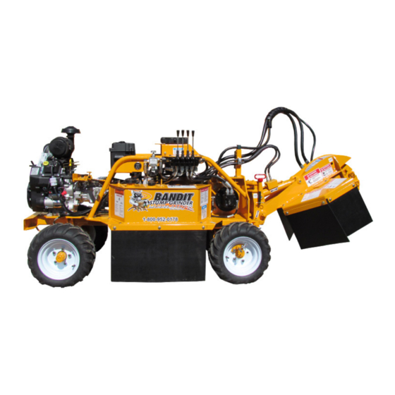
MODEL 2250R
2250R
MANUFACTURED BY
6750 Millbrook Road
Advertisement
Table of Contents

Related Manuals for Brush Bandit 2250R


Summary of Contents for Brush Bandit 2250R
- Page 1 BUILT WITH QUALITY AND DESIGN FIRST STUMP GRINDER ATTENTION: MODEL 2250R Depending on what replacement OPERATING & PARTS MANUAL parts you are ordering, we will need the following information: 2250R Model No: _____________________ GRINDER COMPONENTS Serial Number Serial No: _____________________...
- Page 2 CALIFORNIA PROPOSITION 65 WARNING ADVERTENCIA Breathing diesel engine Respirar gases de escape de exhaust exposes you to motores diesel expone chemicals known to the quÍmicos conocidos por el estado State of California to cause de California como causales de cancer and birth defects or cáncer y defectos congénitos u other reproductive harm.
- Page 3 Copyright 4-14 FORM #WV-124 IT IS VERY IMPORTANT THAT THIS FORM IS FILLED OUT COMPLETELY & ACCURATELY. IF WE CANNOT READ THE PURCHASER’S INFORMATION OR IT IS INCORRECT, OUR CUSTOMER LIST WILL NOT BE ACCURATE. Customer Data Department IMPORTANT - THIS FORM MUST BE RETURNED TO THE 6750 Millbrook Road CUSTOMER DATA DEPARTMENT WITHIN TEN Remus, MI, USA 49340...
- Page 4 Copyright 7-04 FORM #Q-112 DATE PURCHASE: ______________________ TO BE RETURNED AFTER THIRTY (30) DAYS OF OPERATION MODEL: ________________________________ SERIAL NUMBER: _______________________ Please return to: Customer Data Department 6750 Millbrook Road DEALER NAME: ________________________ Remus, MI 49340 _______________________________________ Phone: (800) 952-0178 in USA Phone: (989) 561-2270 Fax: (989) 561-2273...
-
Page 5: Table Of Contents
MODEL 2250R TABLE OF CONTENTS TABLE OF CONTENTS PAGE INTRODUCTION & WARRANTY ............2 SERIAL NUMBER LOCATION ............. 6 SAFETY PROCEDURES ..............7 EQUIPMENT SPECIFICATIONS ............11 DECALS ....................12 CONTROLS.................... 15 MACHINE OPERATION ................ 19 TRANSPORTATION PROCEDURES ........... 23 MAINTENANCE .................. -
Page 6: Introduction & Warranty
INTRODUCTION & WARRANTY INTRODUCTION The purpose of this manual is to provide the user with specifications and procedures for the o peration, m aintenance and repair of this BANDIT product. As with any piece of equipment, safety should always be a constant thought while the machine is being operated, serviced or stored. In order to highlight this consideration, the material which addresses safety is proceeded by the following signal words: Degree of Potential Signal Word... - Page 8 MODEL 2250R SERIAL NUMBER LOCATIONS TYPICAL SERIAL NUMBER AND/OR WORK ORDER NUMBER LOCATIONS NOTICE 1. Side of tank or control box 2. W/O # on pivot mount plate The engine information is located on the engine block. Bandit Copyright 3/15...
-
Page 9: Safety Procedures
MODEL 2250R SAFETY PROCEDURES SAFETY PROCEDURES DANGER The words Danger, Warning, Caution, and DANGER Notice are used on the safety decals and throughout NEVER sit, stand, lay, climb or ride anywhere this manual, to make you aware of the safety on this machine while it is running, operating, or in p rocedures. These procedures are very important,... - Page 10 MODEL 2250R SAFETY PROCEDURES SAFETY PROCEDURES WARNING DANGER It is very important after you have operated a new DO NOT operate this machine indoors! Exhaust machine for approximately an hour to shut down the fumes can be fatal. Never refuel while the machine machine and recheck all nuts and bolts. It is normal is running.
- Page 11 MODEL 2250R SAFETY PROCEDURES SAFETY PROCEDURES NOTICE DANGER Engage and disengage cutter wheel at low rpm. DO NOT go near or in-line with the debris field of the stump grinder while in operation. While grinding NOTICE stumps, the chips and portions of the stump fly from Do not attempt to start the engine or engage the the cutter wheel and can cause severe injury.
- Page 12 MODEL 2250R SAFETY PROCEDURES SAFETY PROCEDURES IF MACHINE IS EQUIPPED WITH A SELF PROPELLED UNDERCARRIAGE Machines equipped with undercarriage tracks are shipped with a manual from the track manufacturer. Refer to it for service, operation, and safety information. WARNING Do not attempt to operate the machine on an ascending or descending slope of more than 25° or 46% or a side slope of more than 17° or 30%, it is Dangerous and could be Fatal. This is the maximum slope grade...
-
Page 13: Equipment Specifications
EQUIPMENT SPECIFICATIONS Approximate Dimensions & Weights (Dimensions & weights will vary depending on optional equipment) Approx. Weight: Model 2250R: 1380 lbs. (625 kg) (Approximate weights depending on engine and equipment options.) Overall Dimension: Model 2250R: Height: 44-1/4” (1.12 m), Length: 112” (2.84 m), Width: 35”... - Page 14 MODEL 2250R DECALS DECAL LOCATIONS Decal locations may vary, these are general locations. 6,14,20,26 1,17,28 1,2,11 8,12,13 16,23,25 7,8,18 1,17,28 1,2,27 19,24 1,8,13 8,23 4,5,10 Bandit Copyright 3/15...
- Page 15 ...Cutter Wheel Stall... 900-8900-34 Basic Safety Decal Kit (Options may require additional decals) 900-8901-90 Bandit Model 2250R Logo Decal Kit NOTICE Some decals are for optional equipment. Decal locations may vary, these are general locations. If any decals become damaged, replace immediately.
-
Page 16: Decals
MODEL 2250R DECALS DECALS Decals located on your Bandit equipment contain useful information to assist you in operating your equipment safely. Some of the decals on your machine and their location are shown in this section. It is very important that all decals remain in place and in good condition on your machine. Please follow the care and instructions given below: You should use soap and water to keep your decals clean. -
Page 17: Controls
MODEL 2250R CONTROLS ENGINE OPERATING SPEEDS NOTICE Refer to the Completion/Check Sheet, that is shipped with the machine for the correct engine rpm. If needed, contact your local dealer or Bandit Industries. Some Current Engine Types Maximum RPM Kohler CH730S - 27 Hp... - Page 18 MODEL 2250R CONTROLS CONTROLS Basic Location of Controls and Components LOCATION SHOWN Hydraulic Speed Control Valve Steer Right / Left 3. Travel Forward / Reverse Cutter Down / Up 5. Boom Travel Left / Right Hour Meter Cutter Wheel Engagement Lever 3 4 5 Bandit Copyright 3/15...
- Page 19 MODEL 2250R CONTROLS CONTROL OPERATING PROCEDURES 1. Hydraulic Speed Control Valve: The Hydraulic Speed Control Valve controls the rate at which hydraulic fluid flows towards each control function such as Travel Forward / Travel Reverse, Steer Right / Steer Left, etc. By rotating the knob clockwise various function speed will slow down. By rotating the knob counter-clockwise various function speed will increase. 2. Steer Right / Left: To steer the machine to the right, push the handle or switch, away from the operator. To steer the machine to the left, pull the handle or switch, towards the operator. The steering is s tationary when the...
- Page 20 MODEL 2250R CONTROLS CONSULT THE ENGINE MANUFACTURER’S MANUAL FOR SPECIFIC CONTROLS, OPERATION, & MAINTENANCE FOR TYPICAL ENGINES 1. Ignition Switch: Turn the ignition switch key clockwise one stop (on position) to turn the electrical system on. The key should remain in the on p osition while the engine is running. Turn the key fully clockwise (start position) this will start the engine. To shut off the engine, return the key to the off position. 2. On/Off Switch - Push Button Start: Some gasoline engines may have a Toggle Switch or an On/Off Switch combined with a push button to start the engine. First turn the On/Off Switch or Toggle Switch to the on position, then depress and hold the Push Button Start until the engine starts, then release the button. To shut off the engine, return the On/Off Switch or Toggle Switch to the off position.
-
Page 21: Machine Operation
MODEL 2250R MACHINE OPERATION MACHINE OPERATION • Check all fluids before starting the machine. • Make sure to go through the daily start-up and maintenance procedures before operating the machine. • Cutter wheel must be disengaged before starting. • Start engine at idle speed and allow for sufficient time for oil to circulate before proceeding. • Test all controls for proper operation. • Avoid transversing slopes. DANGER DO NOT OPERATE AROUND WATER LINES, GAS LINES, POWER LINES, PHONE LINES, ETC. IF IN DOUBT, CHECK BEFORE GRINDING. DANGER WEAR ALL PERSONAL PROTECTIVE EQUIPMENT PER ANSI, OSHA AND MANUALS. - Page 22 MODEL 2250R MACHINE OPERATION CUTTING AREA DANGER For optimum performance, the stump should be cut with the portion of the cutter wheel shown below. NEVER UNDERCUT THE STUMP. Undercutting the stump may cause severe kickback, vibration and component damage. NEVER CUT THE STUMP FROM THE TOP. The cutter wheel will throw debris up and toward the operator, instead of down and under the machine.
- Page 23 MACHINE OPERATION MODEL 2250R TURNING THE MACHINE NOTICE If the machine needs to turn in a small area, the drive lock pin can be pulled out to let the right drive tire free wheel. Only remove the drive lock pin when making a tight turn. Immediately replace the drive lock pin after the turn is achieved. The person running the machine controls should be the person to pull or replace the...
- Page 24 MODEL 2250R MACHINE OPERATION MOVING A MACHINE WITHOUT POWER WARNING Do not attempt to remove drive chain while machine is located on a incline or uneven surface. Machine will roll causing damage to persons, property and or machine. NOTICE Use this procedure only when the machine will not start or run to help prevent damage to the drive system.
-
Page 25: Transportation Procedures
MODEL 2250R TRANSPORTATION PROCEDURES TRANSPORTATION PROCEDURES WARNING BEFORE TRANSPORTING THE MACHINE, INSPECT AND CONFIRM THE FOLLOWING STEPS: 1. The trailer has a cargo weight rating capacity for the weight of the stump grinder. The combined weight of the trailer and the stump grinder can not exceed the load capacity of the tires, axles, hitch coupler system or the GVWR (Gross Vehicle Weight Rating) of the trailer. - Page 26 MODEL 2250R TRANSPORTATION PROCEDURES LOADING & UNLOADING WARNING BEFORE LOADING OR UNLOADING THE MACHINE, INSPECT AND CONFIRM THE FOLLOWING STEPS: When loading or unloading the self-propelled machine on the trailer, use care and caution. The maneuvering of the equipment must be slow, smooth, and intentional, not fast and jerky. DANGER Never load or unload the machine with the drive lock pin pulled out of the rim. Make sure the drive lock pin is in all the way.
-
Page 27: Maintenance
MODEL 2250R MAINTENANCE SECTION MAINTENANCE SECTION The Bandit is a very simple machine to maintain. If you will follow a regular scheduled preventative maintenance program, you should have years of trouble free operation. DANGER Before attempting any type of maintenance disengage clutch, turn off engine, wait for the cutter wheel to come to a complete stop, install the cutter wheel lock pin, place the cutter wheel on the ground, disconnect battery, and make sure the ignition key is in your possession. - Page 28 MODEL 2250R MAINTENANCE SECTION DAILY START UP & MAINTENANCE (cont.) 8. Grease both drive axle bearings daily: 16. Check air cleaner or precleaner: Use an EP-2 Lithium type grease only for all bearings. Clean or replace element following engine manual Grease both drive axle bearings with one shot of recommendations.
- Page 29 MODEL 2250R MAINTENANCE SECTION WEEKLY MAINTENANCE 1. Grease swing pivot assembly bushings: 6. Lube drive axle chain: Grease the top and bottom swing pivot assembly Use a dry lube on the drive axle chain and sprockets. bushings with 1 to 2 shots of EP-2 Lithium type grease.
- Page 30 MODEL 2250R MAINTENANCE SECTION 3 MONTH MAINTENANCE 1. Hydraulic oil filter(s): Must be replaced after FIRST 10 HOURS OF O PERATION, USE A 10 MICRON FILTER. After first change replace oil filter every 3 months or 400 hours. YEARLY MAINTENANCE 1. Grease steering wheel hub bearings: 3. Fuel tank: Inspect and clean the steering wheel hub bearings, Drain and clean the fuel tank yearly.
- Page 31 MODEL 2250R MAINTENANCE SECTION DAILY START UP & MAINTENANCE CHECK LIST Each day before starting your machine these checks must be made: OK Repaired 1. Check the safety decals and engine gauges, replace if damaged. 2. Check, maintain, and service all safety equipment for proper operation.
- Page 32 MODEL 2250R MAINTENANCE SECTION WEEKLY CHECK LIST OK Repaired 1. Grease the top and bottom pivot assembly bushings with 1 to 2 shots. 2. Grease steering axle pivot bushings with 1 to 2 shots. 3. Grease steering bushings with 1 to 2 shots.
- Page 33 MODEL 2250R MAINTENANCE SECTION CUTTER WHEEL ENGAGEMENT LEVER DANGER Before attempting any type of maintenance disengage clutch, turn off engine, wait for the cutter wheel to come to a complete stop, install the cutter wheel lock pin, place the cutter wheel on the ground, disconnect battery, and make sure the ignition key is in your possession.
- Page 34 MODEL 2250R MAINTENANCE SECTION LUBRICATION CHART CHECK # DESCRIPTION DAY WEEK MONTH PROCEDURE Drive Axle Bearings 1 shot of grease - wipe off excess Cutter Wheel Arm Pivot Bushings 1 to 2 shots of grease - wipe off excess Swing Pivot Ass’y Bushings...
- Page 35 MODEL 2250R MAINTENANCE SECTION LUBRICATION CHART Use as a reference only, locations may vary depending on options or component manufacturer. NOTICE Lubrication point instructions are described on the machine, in the Lubrication & Coolant Section and Maintenance Section of this manual, or component manufacturer’s manual.
- Page 36 MAINTENANCE SECTION MODEL 2250R CUTTER WHEEL MOTOR COUPLER DANGER Before attempting any type of maintenance disengage clutch, turn off engine, wait for the cutter wheel to come to a complete stop, install the cutter wheel lock pin, place the cutter wheel on the ground, disconnect battery, and make sure the ignition key is in your possession.
- Page 37 MODEL 2250R MAINTENANCE SECTION CUTTER WHEEL MOTOR COUPLER Stub Shaft Brace Stub Shaft Cutter Wheel Hub Coupler Removal Hole Cutter Wheel Cutter Wheel Motor Coupler Cutter Wheel Motor Shaft Bandit Copyright 3/15...
- Page 38 MODEL 2250R MAINTENANCE SECTION TROUBLE SHOOTING PROBLEM POSSIBLE CAUSE SOLUTION Engine will 1. Loose ground cable. 1. Clean and tighten. not start. (See 2. Loose hot cable. 2. Clean and tighten. Engine Mfg. 3. Dead battery. 3. Recharge or replace.
-
Page 39: Hydraulic Section
MODEL 2250R HYDRAULIC SECTION HYDRAULIC SECTION WARNING It is very important after you have operated a new machine for approximately an hour to shut down the machine and recheck all hydraulic fittings. Retighten as needed. DO NOT GO NEAR HYDRAULIC LEAKS! High pressure oil easily punctures skin causing serious injury, g angrene, or death. Avoid burns from fluid. Hot fluid under pressure can cause severe burns. DO NOT use fingers or skin to check for leaks. Lower load or relieve hydraulic pressure before loosening fittings. Relieve all pressure in the system before d isconnecting the lines, hoses, or performing other work. Use a piece of c ardboard to find leaks. Never use your bare hands. Allow system to cool down to ambient temperature before opening any coolant or hydraulic oil system. - Page 40 MODEL 2250R HYDRAULIC SECTION HYDRAULIC SECTION Alternate hydraulic oils are available, but they do not equal the performance or longevity of the “Hydrex XV” oil. Consult the following information supplied by the oil distributor. CELSIUS (C) -40 -34 -29 -23 -18 -12 -7...
- Page 41 MODEL 2250R HYDRAULIC SECTION HYDRAULIC SECTION TYPICAL HYDRAULIC RELIEF PRESSURE SETTINGS TYPICAL HYDRAULIC FLOWS AND RPM SETTINGS (Approximate, For Reference Only, Engine At Full RPM) Equipment 2250R Model Cutter Wheel Pump GPM (LPM) (143) Function Pump GPM (LPM) (18) Function Main Relief PSI...
- Page 42 MODEL 2250R HYDRAULIC SECTION HYDRAULIC SECTION THE BANDIT HYDRAULIC SYSTEM The Bandit is equipped with a very efficient, simple • Replace hydraulic oil & suction screen(s) at least hydraulic system. Each component is capable of once yearly. This is also a very good time to flush and withstanding a specified PSI (bar) and still operate clean the tank. Replace hydraulic oil immediately if it for a very long time. is contaminated or looks “milky”. See pages 37 - 38 for hydraulic oil requirements.
- Page 43 MODEL 2250R HYDRAULIC SECTION HYDRAULIC SECTION WARNING It is very important after you have operated a new machine for approximately an hour to shut down the machine and recheck all hydraulic fittings. Retighten as needed. DO NOT GO NEAR HYDRAULIC LEAKS! High pressure oil easily punctures skin causing serious injury, g angrene, or death. Avoid burns from fluid. Hot fluid under pressure can cause severe burns. DO NOT use fingers or skin to check for leaks. Lower load or relieve hydraulic pressure before loosening fittings. Relieve all pressure in the system before d isconnecting the lines, hoses, or performing other work. Use a piece of c ardboard to find leaks. Never use your bare hands. Allow system to cool down to ambient temperature before opening any coolant or hydraulic oil system.
- Page 44 MODEL 2250R HYDRAULIC SECTION CHECKING HYDRAULIC PRESSURE The relief valve is typically located internally in the valve bank. Do not adjust the relief valves above the s pecified psi (bar). The relief valve system is a simple spring tension design but small pieces of debris can stick the valve partially open which weakens the hydraulic power. The relief as well as hydraulic oil, and suction screen must be kept clean. WARNING Before attempting any hydraulic pressure settings, make sure engine is shut off, engine key removed and in your possession, hydraulic oil is clean, hydraulic tank is 3/4 to 7/8 full, and the machine has been pre-run to warm the hydraulic oil. To correctly check relief valve pressure, gauge MUST be installed correctly.
- Page 45 MODEL 2250R HYDRAULIC SECTION CHECKING HYDRAULIC PRESSURE cont. The relief valve is typically located internally in the valve bank. Do not adjust the relief valves above the s pecified psi (bar). The relief valve system is a simple spring tension design but small pieces of debris can stick the valve partially open which weakens the hydraulic power. The relief as well as hydraulic oil, and suction screen must be kept clean. WARNING Before attempting any hydraulic pressure settings, make sure engine is shut off, engine key removed and in your possession, hydraulic oil is clean, hydraulic tank is 3/4 to 7/8 full, and the machine has been pre-run to warm the hydraulic oil. To correctly check relief valve pressure, gauge MUST be installed correctly.
- Page 46 MODEL 2250R HYDRAULIC SECTION HYDRAULIC SYSTEM TROUBLE SHOOTING Before attempting any type of maintenance disengage clutch, turn off engine, wait for the cutter wheel to come to a complete stop, install the cutter wheel lock pin, place the cutter wheel on the ground, disconnect battery, and make sure the ignition key is in your possession.
- Page 47 MODEL 2250R HYDRAULIC SECTION MODEL 2250R SPECIFIC SCHEMATIC FUNCTION MAY VARY DEPENDING ON OPTIONS OR COMPONENT MANUFACTURE. NOTICE Parts may not be exactly as shown. Bandit Copyright 3/15...
-
Page 48: Cutter Wheel Section
NEVER USE HAND ON CUTTER WHEEL TO HOLD IN PLACE WHILE CHANGING TEETH. BE SURE TO REMOVE LOCKING PIN BEFORE OPERATING THE MACHINE. NOTICE Do Not operate machine with extremely worn or broken teeth. MODEL 2250R TOOTH ARRANGEMENT Inspect teeth, nuts and pockets for damage and To make sure the correct tooth pattern is used, make replace as required. - Page 49 TO REMOVE LOCKING PIN BEFORE OPERATING THE MACHINE. NOTICE Do Not operate machine with extremely worn or broken teeth. MODEL 2250R TOOTH ARRANGEMENT Inspect pockets, teeth and bolts for damage and When replacing complete set of teeth, be sure replace as required.
- Page 50 MODEL 2250R ELECTRICAL SECTION 2250R MACHINE HARNESS (206-8000-01) SPECIFIC SCHEMATIC FUNCTION MAY VARY DEPENDING ON OPTIONS OR COMPONENT MANUFACTURE. Bandit Copyright 3/15...
-
Page 51: Electrical Section
MODEL 2250R ELECTRICAL SECTION 2250R POSITIVE BATTERY CABLE (206-8000-02) SPECIFIC SCHEMATIC FUNCTION MAY VARY DEPENDING ON OPTIONS OR COMPONENT MANUFACTURE. 900-2903-20 900-2909-99 900-2909-99 900-2905-43 900-2920-44 900-2920-44 TO STARTER TO BATTERY 900-2909-07 2250R NEGATIVE BATTERY CABLE (206-8000-03) SPECIFIC SCHEMATIC FUNCTION MAY VARY DEPENDING ON OPTIONS OR COMPONENT MANUFACTURE. 900-2909-69 900-2909-69 900-2905-42 900-2920-44 900-2920-44 TO STARTER TO BATTERY 900-2909-07 Bandit... -
Page 52: Lubrication & Coolant
MODEL 2250R LUBRICATION & COOLANT LUBRICATION & COOLANT 1. Engine: Follow original equipment manufacturer’s requirements for both changing oils and filters, refer to engine manual s pecifications. 2. Engine Coolant: Refer to engine manufacturer’s manual specifications. 3. Hydraulic Reservoir Tank: Completely change hydraulic oil, suction screen(s), and flush the tank a nnually. Change h ydraulic oil filter AFTER FIRST 10 HOURS OF OPERATION. Then change hydraulic oil filter every 3 months or 400 hours thereafter. Maintain hydraulic oil level 3/4 to 7/8 full. See hydraulic oil requirements below. Check hydraulic oil level in tank daily. -
Page 53: Replacement Parts Section
MODEL 2250R REPLACEMENT PARTS REPLACEMENT PARTS SECTION Depending on what replacement parts you are ordering the following information will be needed: GRINDER COMPONENTS ENGINE COMPONENTS Serial Number Brand Model Number of Grinder Engine Serial Number Engine Spec. Number NOTICE When ordering any replacement parts you should have the serial number (S/N) and model of the machine to ensure that you receive the correct replacement part. - Page 54 MODEL 2250R FRAME COMPONENTS MODEL 2250R FRAME COMPONENTS NOTICE Parts may not be exactly as shown. NOTICE Nuts, bolts, washers, and all other components can be ordered by physical description. Bandit Copyright 3/15...
-
Page 55: Frame Components
MODEL 2250R FRAME COMPONENTS MODEL 2250R FRAME COMPONENTS LOCATION PART NUMBER DESCRIPTION 900-4914-00 1/2”-20NF Lug Nut 203-2000-33 Wheel Lock Holder 900-4916-32 Hub Lock Pin 3 a. 900-5909-22 18” x 8.50” - 10” Tire & White, 5 Bolt Rim (Specify Left or Right) 900-5909-20 18” x 8.50” - 10” Tire Only 900-5909-21 10” x 6” White, 5 Bolt Rim Only 900-4909-08 1”-8NC Slotted Hex Nut 900-4911-75 3/16”... - Page 56 MODEL 2250R CUTTER WHEEL ARM COMPONENTS MODEL 2250R CUTTER WHEEL ARM COMPONENTS NOTICE Parts may not be exactly as shown. NOTICE Nuts, bolts, washers, and all other components can be ordered by physical description. Bandit Copyright 3/15...
-
Page 57: Cutter Wheel Arm Components
MODEL 2250R CUTTER WHEEL ARM COMPONENTS MODEL 2250R CUTTER WHEEL ARM COMPONENTS LOCATION PART NUMBER DESCRIPTION 206-2000-07 Chip Pan 203-3002-97 Chip Curtain - 14” Wide 203-3001-49 Chip Curtain Strap - 14” 203-3002-98 Chip Curtain - 17” Wide 203-3001-44 Chip Curtain Strap - 17”... - Page 58 MODEL 2250R CUTTER WHEEL COMPONENTS CUTTER WHEEL & TEETH COMPONENTS NEW RIVER “REVOLUTION” CUTTER WHEEL & TEETH BANDIT CUTTER WHEEL WITH GREEN TEETH NOTICE Parts may not be exactly as shown. NOTICE Nuts, bolts, washers, and all other components can be ordered by physical description. Bandit Copyright 3/15...
-
Page 59: Cutter Wheel Components
MODEL 2250R CUTTER WHEEL COMPONENTS CUTTER WHEEL & TEETH COMPONENTS LOCATION PART NUMBER DESCRIPTION 900-4918-43 14mm x 55mm Hex Head Bolt 900-3959-06 Cutter Wheel Motor 900-3951-91 Manifold Block For Cutter Wheel Motor 900-4907-88 14mm Hex Nut 4. 900-1919-18 Taper Lock Coupler 203-3002-57 Cutter Wheel Hub - New Revolution Wheel b. -
Page 60: Steering Components
MODEL 2250R STEERING COMPONENTS MODEL 2250R STEERING COMPONENTS LOCATION PART NUMBER DESCRIPTION 206-2000-01 Pivot Steering Mount 900-4911-84 Grease Zerk - 1/4” 900-1902-50 Split Bushing - 1-1/4” OD x 1” ID x 1-1/2” 900-4900-80 1”-8NC Nylon Insert Hex Lock Nut 4. 900-4913-38 1”-8NC x 5-1/2” Hex Head Bolt (1-1/4” of Thread) - Special... -
Page 61: Cutter Wheel Engagement Lever Components
MODEL 2250R CUTTER WHEEL ENGAGEMENT LEVER COMPONENTS CUTTER WHEEL ENGAGEMENT LEVER COMPONENTS LOCATION PART NUMBER DESCRIPTION 206-1000-07 Complete Cutter Wheel Engagement Lever Assembly 206-2000-11 Cutter Wheel Engagement Lever Mount Assembly 900-4909-75 1/4”-20NC Cutter Wheel Engagement Lever Mount Bolt 900-9906-75 Black Plastic Handle... -
Page 62: Fuel Tank Components
MODEL 2250R FUEL TANK COMPONENTS FUEL TANK COMPONENTS LOCATION PART NUMBER DESCRIPTION 1 a. 206-1000-09 Fuel Tank Assembly (Start ??/??) 206-1000-06 Fuel Tank Assembly (Pre ??/??) 206-2000-19 Fuel Tank Weldment (Start ??/??) 206-2000-09 Fuel Tank Weldment (Pre ??/??) 2 a. 900-2929-09 Rochester Sight Gauge for Fuel Tank - 8” 900-2903-55 Face for Sight Gauge Only 3. 900-3943-22 1/4” NPTF To 3/16” Hose Barb 900-3909-03 Suction Pipe Assembly 5. a. -
Page 63: Hydraulic Tank Components
MODEL 2250R HYDRAULIC TANK COMPONENTS HYDRAULIC TANK COMPONENTS LOCATION PART NUMBER DESCRIPTION 988-300134 Clean Out Door - Hydraulic tank 900-3950-33 Rubber O-Ring 900-3944-78 Suction Screen 900-3922-60 Magnetic Drain Plug 5. 900-3900-44 Glass Sight Gauge for Hydraulic Tank 900-3941-30 Hydraulic Locking Fill Cap - Black 900-4912-40 Padlock With Short Shackle for Tank With Locking Cap (Not Shown) - Page 64 MODEL 2250R HYDRAULIC COMPONENTS MODEL 2250R HYDRAULIC COMPONENTS NOTICE Parts may not be exactly as shown. NOTICE Make sure to order components according to fitting type, fittings may vary on all components. Hydraulic components, fittings, hoses will vary depending on optional equipment.
-
Page 65: Hydraulic Components
MODEL 2250R HYDRAULIC COMPONENTS MODEL 2250R HYDRAULIC COMPONENTS LOCATION PART NUMBER DESCRIPTION 900-3951-91 Cutter Wheel Motor Manifold Relief 900-3956-04 Relief Only 900-3959-06 Cutter Wheel Motor 900-3958-80 Swing Cylinder 900-3941-35 Cutter Wheel Lift Cylinder 5. 900-3944-78 Hydraulic Tank Strainer 6 a. 900-3951-32 In-Tank Hydraulic Oil Filter Only 900-3951-31 In-Tank Return Filter Assembly - Includes Filter 7. - Page 66 MODEL 2250R HYDRAULIC COMPONENTS MODEL 2250R HYDRAULIC COMPONENTS In-Tank Return Filter Ass’y: 900-3951-31 Suction Screen: 900-3944-78 In-Tank Hydraulic Oil Filter Only: 900-3931-52 Double Counter Balance: 900-3956-84 Shuttle Valve Only: 900-3943-52 Counter Balance Relief Only: 900-3929-09 Shuttle Valve Block Only: 900-3943-55 Manual Control Valve - 4 Bank: 900-3952-74 Cross Line Swing Relief: 900-3965-16...
- Page 67 MODEL 2250R HYDRAULIC COMPONENTS MODEL 2250R HYDRAULIC COMPONENTS Swing Cylinder: 900-3958-80 Steering Cylinder: 900-3937-68 Cutter Wheel Lift Cylinder: 900-3941-35 Cutter Wheel Pump: 900-3963-72 NOTICE Parts may not be exactly as shown. Bandit Copyright 3/15...
- Page 68 MODEL 2250R HYDRAULIC COMPONENTS MODEL 2250R HYDRAULIC COMPONENTS Cutter Wheel Motor Manifold Relief: 900-3951-91 Cutter Wheel Motor: 900-3959-06 Relief Only: 900-3956-04 Braking Drive Motor: 900-3952-49 Flow Control: 900-3965-15 Oil Cooler: 900-3953-06 Oil Cooler Temperature Switch: 900-3966-18 NOTICE Parts may not be exactly as shown.
-
Page 69: Service Record
MODEL 2250R SERVICE RECORD SERVICE RECORD DATE DESCRIPTION AMOUNT Bandit Copyright 3/15... - Page 70 MODEL 2250R SERVICE RECORD SERVICE RECORD DATE DESCRIPTION AMOUNT Bandit Copyright 3/15...
Need help?
Do you have a question about the 2250R and is the answer not in the manual?
Questions and answers