Table of Contents
Advertisement
ATTENTION:
Depending on what replacement
parts you are ordering, we will
need the following information:
GRINDER COMPONENTS
Serial Number
Model Number of Grinder
ENGINE COMPONENTS
Brand
Engine Serial Number
Engine Spec. Number
CLUTCH COMPONENTS
Brand
Serial Number
Assembly of Clutch
STUMP GRINDER
OPERATING & PARTS MANUAL
Model No: _________________
Serial No: _________________
DEALER:
Name: ____________________
Address: __________________
City/State: _________________
Phone No: _________________
Delivery Date: ______________
Engine Make: ______________
Serial No: _________________
Clutch Make: _______________
Model: _________ S/N _______
Copyright 1/07
BANDIT INDUSTRIES, INC.
REMUS, MICHIGAN, USA 49340
PHONE: (800) 952-0178 IN USA
PHONE: (989) 561-2270 OR 561-2272
FAX: (989) 561-2273 ~ SALES DEPT.
FAX: (989) 561-2962 ~ PARTS/SERVICE
E-MAIL: www.banditchippers.com
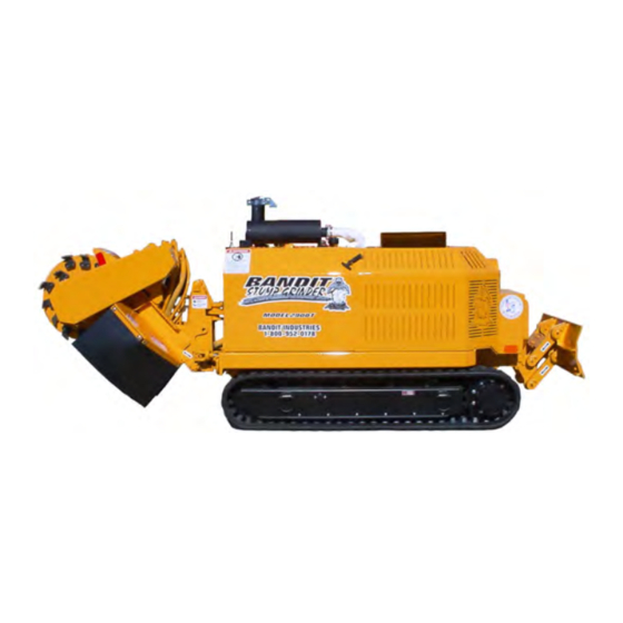
MODEL 2900T
2900T
MANUFACTURED BY
6750 Millbrook Road
Advertisement
Table of Contents
Troubleshooting

Related Manuals for Brush Bandit 2900T


Summary of Contents for Brush Bandit 2900T
- Page 1 STUMP GRINDER ATTENTION: Depending on what replacement MODEL 2900T parts you are ordering, we will need the following information: OPERATING & PARTS MANUAL GRINDER COMPONENTS Serial Number 2900T Model Number of Grinder Model No: _________________ ENGINE COMPONENTS Serial No: _________________...
- Page 3 Copyright 11-06 FORM #WV-124 IT IS VERY IMPORTANT THAT THIS FORM IS FILLED OUT COMPLETELY & ACCURATELY. IF WE CANNOT READ THE PURCHASER’S INFORMATION OR IT IS INCORRECT, OUR CUSTOMER LIST WILL NOT BE ACCURATE. Customer Data Department IMPORTANT - THIS FORM MUST BE RETURNED TO THE 6750 Millbrook Road CUSTOMER DATA DEPARTMENT WITHIN TEN (10)
- Page 5 Copyright 7-04 FORM #Q-112 DATE PURCHASED: _________________ TO BE RETURNED AFTER THIRTY (30) DAYS OF OPERATION MODEL: ___________________________ Please return to: Customer Data Department SERIAL NUMBER: ___________________ 6750 Millbrook Road DEALER NAME: ____________________ Remus, MI 49340 ___________________________________ (800) 952-0178 in USA (989) 561-2270 FAX: (989) 561-2273 E-MAIL: www.banditchippers.com...
- Page 7 MODEL 2900T TABLE OF CONTENTS TABLE OF CONTENTS PAGES INTRODUCTION & WARRANTY ............. SERIAL NUMBER LOCATIONS ............SAFETY PROCEDURES ..............EQUIPMENT SPECIFICATIONS ............11 DECALS ................... CONTROLS ..................15 MACHINE OPERATION ..............19 TRANSPORTATION PROCEDURES ..........21 MAINTENANCE ................HYDRAULIC SECTION ............31 CUTTER WHEEL SECTION ............
- Page 8 INTRODUCTION & WARRANTY INTRODUCTION The purpose of this manual is to provide the user with specifications and procedures for the operation, maintenance and repair of this BANDIT product. As with any piece of equipment, safety should always be a constant thought while the machine is being operated, serviced or stored. In order to highlight this consideration, the material which addresses safety is proceeded by the following signal words: Degree of Potential Signal Word...
- Page 10 MODEL 2900T SERIAL NUMBER LOCATIONS TYPICAL GRINDER SERIAL NUMBER AND/OR WORK ORDER NUMBER LOCATIONS 1. Serial Number NOTE: The engine information is located on the engine block. The clutch information 2. Work Order Number is located on the clutch plate (if equipped).
- Page 11 MODEL 2900T SAFETY PROCEDURES SAFETY PROCEDURES DANGER The words Danger, Warning, Caution, and DANGER Notice are used on the safety decals and throughout this manual, to make you aware of the safety Before starting the machine, take a minute to check a procedures.
- Page 12 MODEL 2900T SAFETY PROCEDURES SAFETY PROCEDURES DANGER DANGER NEVER sit, stand, lay, climb or ride anywhere Do not go near or in-line with the debris field of on this machine while it is running, operating, or in the stump grinder while in operation. While grinding stumps, the chips and portions of the stump fly from transit.
- Page 13 MODEL 2900T SAFETY PROCEDURES SAFETY PROCEDURES DANGER NOTICE Never grind any materials that might contain wires, Do not attempt to start the engine or engage the engine PTO (power-take-off) system on this machine stones, nails, or other metal objects which may if the cutter wheel is jammed or frozen in place.
- Page 14 MODEL 2900T SAFETY PROCEDURES SAFETY PROCEDURES IF MACHINE IS EQUIPPED WITH UNDERCARRIAGE TRACK Machines equipped with undercarriage tracks are shipped with a manual from the track manufacturer. Refer to it for service, operation, and safety information. WARNING Do not attempt to operate the track machine on an ascending or descending slope of more than 25° or 46% or a side slope of more than 17°...
- Page 15 MODEL 2900T EQUIPMENT SPECIFICATIONS EQUIPMENT SPECIFICATIONS CUTTER HEAD WIDTH SWING LENGTH TOP OF CUTTER HEIGHT CENTER OF WHEEL CUTTER WHEEL CUTTING DEPTH BELOW GROUND Approximate Dimensions & Weights (Dimensions & weights will vary depending on optional equipment) Approx. Weight: 4300 to 4600 lbs. (1950 to 2087 kg) (Approximate weights depending on engine and equipment options.)
- Page 16 MODEL 2900T DECALS DECAL LOCATIONS Decal locations may vary, these are general locations. 3,6,7,12,21 14,20 24,26,28,29,31 2,5,8,11,18, 22,27,30 Bandit Copyright 1/07 PAGE 12...
- Page 17 ...Go Slow Around Corners... SPW-11 Do Not Leave Unit Parked On A Slope... Bandit Model 2900T Vinyl Decals Note: Some decals are for optional equipment. Decal Locations may vary, these are general locations. If any decals become damaged , replace immediately.
- Page 18 MODEL 2900T DECALS DECALS Decals located on your Bandit equipment contain useful information to assist you in operating your equipment safely. Some of the decals on your machine and their location are shown in this section. It is very important that all decals remain in place and in good condition on your machine. Please follow the care and instructions given below: 1) You should use soap and water to keep your decals clean.
- Page 19 MODEL 2900T CONTROLS Basic Location of Controls and Adjustments LOCATION SHOWN Key Switch Tachometer, Hour Meter Belt Tensioner Poly Chain (Cutter Wheel) Belt Debris Clean Out Door Hydraulic Control Valve Grinder Teeth Upper Frame Lock Pin Hole Cutter Wheel Lock Pin Hole...
- Page 20 MODEL 2900T CONTROLS CONTROLS Basic Location of Controls and Adjustments LOCATION SHOWN Travel Speed Control 11. Remote / Local Swing Speed Control 12. Swing Enable / Blade Enable Key Switch (Deutz Engine) 13. Left Track Forward / Reverse Tach / Hour Meter 14.
- Page 21 MODEL 2900T CONTROLS CONTROL OPERATING PROCEDURES 1. Travel Speed Control: Controls the rate the machine approaches the stump. To increase the travel speed control turn the knob clockwise. To decrease the travel speed control turn the knob counter clockwise. 2. Swing Speed Control: The swing speed controls the rate the cutter wheel passes through the stump.
- Page 22 MODEL 2900T CONTROLS CONSULT THE ENGINE MANUFACTURER’S MANUAL FOR SPECIFIC CONTROLS, OPERATION, & MAINTENANCE FOR TYPICAL ENGINES Ignition Switch: Turn the ignition switch key clockwise one stop (on position) to turn the electrical system on. The key should remain in the on position while the engine is running.
- Page 23 MODEL 2900T MACHINE OPERATION MACHINE OPERATION • Check all fluids before starting the machine. • Make sure to go through the daily start-up and maintenance procedures before operating the machine. See pages 23 - 25. • Drive belts (if equipped) must be disengaged before starting.
- Page 24 MODEL 2900T MACHINE OPERATION MACHINE OPERATION (cont.) Continue in this manner until stump has been DO NOT ENGAGE OR DISENGAGE DRIVE BELTS removed. AT A HIGH ENGINE SPEED. Damage to belts and machine will occur. Larger stumps may require repositioning machine to remove complete stump.
- Page 25 MODEL 2900T TRANSPORTATION PROCEDURES Transportation Procedures WARNING BEFORE TRANSPORTING THE MACHINE INSPECT AND CONFIRM THE FOLLOWING STEPS: The trailer has a cargo weight rating capacity for the weight of the stump grinder. The combined weight of the trailer and the stump grinder can not exceed the load capacity of the tires, axles, hitch coupler system or the GVWR (Gross Vehicle Weight Rating) of the trailer.
- Page 26 MODEL 2900T TRANSPORTATION PROCEDURES Loading & Unloading WARNING BEFORE LOADING OR UNLOADING THE MACHINE INSPECT AND CONFIRM THE When loading or unloading the self-propelled stump grinder on the trailer, use care FOLLOWING STEPS: and caution. The maneuvering of the equipment must be slow, smooth, and intentional, not fast and jerky.
- Page 27 MODEL 2900T MAINTENANCE SECTION MAINTENANCE SECTION The Bandit is a very simple machine to maintain. If you will follow a regular scheduled preventative maintenance program you should have years of trouble free operation. DANGER Before attempting any type of maintenance disengage clutch, turn off engine, wait for the cutterwheel to come to a complete stop, install the cutter wheel lock pin, place cutter wheel on the ground, disconnect battery, and make sure the ignition key is in your possession.
- Page 28 MODEL 2900T MAINTENANCE SECTION DAILY START UP & MAINTENANCE cont. 7) Check cutter teeth bolts: 15) Check the fuel level: Check the fuel level, running out and repriming is time All cutter teeth bolts must be factory approved. Bolts must be replaced after a maximum of 4-5 consuming.
- Page 29 MODEL 2900T MAINTENANCE SECTION WEEKLY MAINTENANCE 1) Grease cylinder lug pin bushings: 4) Check and retighten tank mount bolts: Check the fuel tank and hydraulic tank mount bolts Grease cylinder lug pin bushings with 1 to 2 shots of EP-2 Lithium type grease. Wipe off excessive grease.
- Page 30 MODEL 2900T MAINTENANCE SECTION DAILY START UP & MAINTENANCE CHECK LIST Each day before starting your machine these checks must be made: O.K. Repaired Check the safety decals and engine gauges, replace if damaged. Check, maintain, and service all safety equipment for proper operation: Check entire machine for loose nuts, bolts, and components.
- Page 31 MODEL 2900T MAINTENANCE SECTION WEEKLY CHECK LIST O.K. Repaired Grease cylinder lug pin bushings with 1 to 2 shots. Grease upper frame pivot bushings with 1 to 2 shots. Check set screws in bearings. Check and retighten fuel tank and hydraulic tank mount bolts.
- Page 32 MODEL 2900T MAINTENANCE SECTION MAINTENANCE SECTION BOLT TORQUE CHART (THESE TORQUES ARE BASED ON DRY, CLEAN THREADS) DESCRIPTION BOLT SIZE TORQUE (FT.-LBS.) TORQUE (Nm) Grinder Bearing Bolts 5/8”-11 NC Grinder Bearing Set Screws Engine Hold Downs 1/2”-13 NC Hydrostatic Motor Cog Bushing...
- Page 33 MODEL 2900T MAINTENANCE SECTION CHECK DESCRIPTION DAY WEEK MONTH PROCEDURE Grinder Bearings Purge bearings daily - wipe off excess Bottom Pivot Bushings 1 to 2 shots of grease - wipe off excess Track Expansion Assembly 1 to 2 shots of grease - wipe off excess Tracks See manufacturer’s specs...
- Page 34 MODEL 2900T MAINTENANCE SECTION TROUBLE SHOOTING PROBLEM POSSIBLE CAUSE SOLUTION Engine will not start. 1. Loose ground cable. 1. Clean and tighten. (See Engine MFG. 2. Loose hot cable. 2. Clean and tighten. manual for further 3. Dead battery. 3. Recharge or replace.
- Page 35 MODEL 2900T HYDRAULIC SECTION HYDRAULIC SECTION WARNING DO NOT GO NEAR HYDRAULIC LEAKS! High pressure oil easily punctures skin causing serious injury, gangrene, or death. If injured, seek emergency medical help. Immediate surgery is required to remove oil. DO NOT use fingers or skin to check for leaks. Lower load or relieve hydraulic pressure before loosening fittings.
- Page 36 MODEL 2900T HYDRAULIC SECTION HYDRAULIC SECTION Alternate hydraulic oils are available, but they do not equal the performance or longevity of the “Hydrex XV” oil. Consult the following information supplied by the oil distributor. CELCIUS -23 -18 +21 +27 FAHRENHEIT...
- Page 37 MODEL 2900T HYDRAULIC SECTION HYDRAULIC SECTION THE BANDIT HYDRAULIC SYSTEM The Bandit is equipped with a very efficient, simple • Keep hydraulic oil clean. Dirty oil will cause excessive hydraulic system. Each component is capable of wear and loss of hydraulic power.
- Page 38 MODEL 2900T HYDRAULIC SECTION NOTICE DO NOT UNDER ANY CIRCUMSTANCES OVER-SET THESE RELIEF PRESSURES, BECAUSE IT WILL CAUSE DAMAGE TO COMPONENT PARTS AS WELL AS HYDRAULIC PARTS. NOTE: These Typical Hydraulic Flows And Relief Pressure Settings Are With The Engine At Full RPM. All...
- Page 39 MODEL 2900T HYDRAULIC SECTION The relief valve is typically located internally in the valve bank. Do not adjust the relief valves above the specified psi (bar). The relief valve system is a simple spring tension design but small pieces of debris can stick the valve partially open which weakens the hydraulic power.
- Page 40 MODEL 2900T HYDRAULIC SECTION High Pressure Filter Auxiliary Pump Hydrostatic Pump Cutter Wheel Valve Cross Line Relief Hydrostatic Motor Bandit Copyright 1/07 PAGE 36...
- Page 41 MODEL 2900T HYDRAULIC SECTION Hydraulic Manifold Track Proportionater Two Speed For Tracks Filter Gauge Cutter Lift Cylinder Counter Balance Hydraulic Oil Filter Super Sweep Valve Bandit Copyright 1/07 PAGE 37...
- Page 42 MODEL 2900T HYDRAULIC SECTION TROUBLE SHOOTING BEFORE ATTEMPTING ANY TYPE OF MAINTENANCE DISENGAGE CLUTCH, TURN OFF ENGINE, WAIT FOR THE CUTTER WHEEL TO COME TO A COMPLETE STOP, INSTALL THE CUTTER WHEEL LOCK PIN, DISCONNECT BATTERY, AND MAKE SURE THE IGNITION KEY IS IN YOUR POSSESSION.
- Page 43 MODEL 2900T HYDRAULIC SECTION CORRECTING HYDRAULIC PROBLEMS BEFORE ATTEMPTING ANY TYPE OF MAINTENANCE DISENGAGE CLUTCH, TURN OFF ENGINE, WAIT FOR THE CUTTER WHEEL TO COME TO A COMPLETE STOP, INSTALL THE CUTTER WHEEL LOCK PIN, DISCONNECT BATTERY, AND MAKE SURE THE IGNITION KEY IS IN YOUR POSSESSION.
- Page 44 MODEL 2900T HYDRAULIC SECTION HYDRAULIC SCHEMATIC SPECIFIC SCHEMATIC FUNCTION MAY VARY DEPENDING ON OPTIONS OR COMPONENT MANUFACTURER. Bandit Copyright 1/07 PAGE 40...
- Page 45 A locking pin is provided to hold the cutter wheel There are twenty-eight (28) teeth to a complete set on a model 2900T. Two (2) straight teeth, thirteen (13) in position during tooth removal and reinstallation. left 45° teeth, and thirteen (13) right 45° teeth.
- Page 46 MODEL 2900T BELT SECTION BELT TENSION GENERAL RULES FOR TENSIONING 1. Check tensioning during the first 2-48 hours of run-in operation. 2. Over tensioning or under tensioning shortens belt and bearing life. 3. Keep belts free from foreign materials that may cause the belt to slip.
- Page 47 MODEL 2900T BELT SECTION POLY CHAIN BELT Sprocket Alignment and Installation Sprocket and pulley alignment is very important. Proper alignment allows the load to be transferred equally across belt width, which reduces wear and improves belt life. 1. Place a straight edge on the outside of the drive pulley, making sure that the straight edge touches the outside and inside of the pulley.
- Page 48 MODEL 2900T LUBRICATION & COOLANT LUBRICATION & COOLANT 1) Engine: Follow original equipment manufacturers requirements for both changing oils and filters, refer to engine manual specifications. 2) Engine Coolant: Refer to engine manufacturers manual specifications. 3) Tracks: Follow track manufacturer’s requirements for specific track lubricating procedures.
- Page 49 MODEL 2900T ELECTRICAL SECTION ELECTRICAL SCHEMATIC WIRING HARNESS SPECIFIC SCHEMATIC FUNCTION MAY VARY DEPENDING ON OPTIONS OR COMPONENT MANUFACTURER. Bandit Copyright 1/07 PAGE 45...
- Page 50 MODEL 2900T ELECTRICAL SECTION ELECTRICAL SCHEMATIC ENGINE PANEL SPECIFIC SCHEMATIC FUNCTION MAY VARY DEPENDING ON OPTIONS OR COMPONENT MANUFACTURER. Bandit Copyright 1/07 PAGE 46...
- Page 51 MODEL 2900T ELECTRICAL SECTION ELECTRICAL SCHEMATIC FUSED RELAY BLOCK SPECIFIC SCHEMATIC FUNCTION MAY VARY DEPENDING ON OPTIONS OR COMPONENT MANUFACTURER. Bandit Copyright 1/07 PAGE 47...
- Page 52 MODEL 2900T ELECTRICAL SECTION ELECTRICAL SCHEMATIC CONTROL SWITCH PANEL SPECIFIC SCHEMATIC FUNCTION MAY VARY DEPENDING ON OPTIONS OR COMPONENT MANUFACTURER. Bandit Copyright 1/07 PAGE 48...
- Page 53 MODEL 2900T REPLACEMENT PARTS REPLACEMENT PARTS SECTION Depending on what replacement parts you are ordering the following information will be needed: GRINDER COMPONENTS ENGINE COMPONENTS CLUTCH COMPONENTS Serial Number Brand Brand Model Number of Grinder Engine Serial Number Serial Number Engine Spec.
- Page 54 MODEL 2900T UPPER FRAME COMPONENTS NOTE: Parts may not be exactly as shown. Bandit Copyright 1/07 PAGE 50...
- Page 55 MODEL 2900T UPPER FRAME COMPONENTS LOCATION PART NUMBER DESCRIPTION 989-100082 Cutter Wheel Guard 989-100062 Upper Frame Assembly 3 a. 989-100097 Hydrostatic Motor Mount 900-4912-51 Jack-Screw Adjuster - 5/8”-18NF x 6 1/2” Hex Head Bolt (Not Shown) 900-4907-06 5/8”-18NF Nut 989-300497...
- Page 56 MODEL 2900T CUTTER WHEEL COMPONENTS NOTE: Parts may not be exactly as shown. Bandit Copyright 1/07 PAGE 52...
- Page 57 MODEL 2900T CUTTER WHEEL COMPONENTS LOCATION PART NUMBER DESCRIPTION 900-4906-71 1/2”-13NC x 1 1/4” Hex Head Bolt 989-300006 Cutter Wheel Washer 3 a. 900-4903-39 5/8”-11NC Automation Lock Nut 900-4910-96 5/8” Mill Carb Washer 900-4906-96 5/8”-11NC x 2 3/4” Hex Head Bolt...
- Page 58 MODEL 2900T FRAME COMPONENTS NOTE: Parts may not be exactly as shown. Bandit Copyright 1/07 PAGE 54...
- Page 59 MODEL 2900T FRAME COMPONENTS LOCATION PART NUMBER DESCRIPTION 1 a. 900-5907-70 Rubber Track Undercarriage - Aggressive 900-5907-75 Rubber Track Undercarriage - Turf Friendly 900-1908-37 Split Bushing - 1 1/2” ID x 1 3/4” OD x 1 1/2” 900-9902-07 Manual Holder...
- Page 60 MODEL 2900T CHIP PAN COMPONENTS LOCATION PART NUMBER DESCRIPTION 994-300035 Rear Chip Pan 994-300038 Curtain Mount 994-300127 Chip Curtain 994-300177 Chip Pan Support 994-300209 Chip Pan Support NOTE: Nuts, bolts, washers, and all other components can be ordered by physical description.
- Page 61 MODEL 2900T CONTROL BOX COMPONENTS LOCATION PART NUMBER DESCRIPTION 989-100106 Control Box Assembly 900-9905-35 Rubber Stop 900-2908-63 Cap And Chain For Tether Jack 989-300812 Top Door 989-300811 Bottom Door 900-2911-29 LOFA Panel Key Switch 7 a. 989-300905 Dash Panel 900-2912-45...
- Page 62 MODEL 2900T GRADING BLADE COMPONENTS LOCATION PART NUMBER DESCRIPTION 900-3930-70 Grading Blade Cylinder 900-1909-26 Split Bushing - 1” ID x 1 1/4” OD 989-200016 Grading Blade Mount - Right 989-200017 Grading Blade Cylinder Pin - 8” Long 989-200018 Cylinder Mount 900-1908-38 Split Bushing - 3/4”...
- Page 63 MODEL 2900T REMOTE CONTROL COMPONENTS LOCATION PART NUMBER DESCRIPTION 1 a. 900-2911-81TX Radio Remote Control With Throttle Control & Blade 900-2911-81BTX Radio Remote Control With Bump Feature, Throttle Control, & Blade (Not Shown) 2 a. 900-2911-81TH Tether Cord - 25’...
- Page 64 MODEL 2900T HYDRAULIC COMPONENTS HYDRAULIC COMPONENTS (START 7/06) NOTE: Parts may not be exactly as shown. Bandit Copyright 1/07 PAGE 60...
- Page 65 MODEL 2900T HYDRAULIC COMPONENTS HYDRAULIC COMPONENTS (START 7/06) LOCATION PART NUMBER DESCRIPTION See Pages 54-55 Hydraulic Tank 900-3901-41 Suction Screen 3 a. 900-3900-10 Hydraulic Oil Filter 900-3900-09 Filter Head 900-3901-73 Filter Gauge See Track Manual Track Expansion Cylinder 975-300464 Manifold For Track Cylinders...
- Page 66 MODEL 2900T HYDRAULIC COMPONENTS HYDRAULIC COMPONENTS (PRE 7/06) NOTE: Parts may not be exactly as shown. Bandit Copyright 1/07 PAGE 62...
- Page 67 MODEL 2900T HYDRAULIC COMPONENTS HYDRAULIC COMPONENTS (PRE 7/06) LOCATION PART NUMBER DESCRIPTION See Pages 54-55 Hydraulic Tank 900-3901-41 Suction Screen 3 a. 900-3900-10 Hydraulic Oil Filter 900-3900-09 Filter Head 900-3901-73 Filter Gauge See Track Manual Track Expansion Cylinder 900-3927-47 Swing Cylinder...
- Page 68 MODEL 2900T HYDRAULIC COMPONENTS Hydraulic Manifold Cutter Wheel Valve NOTE: Parts may not be exactly as shown. Bandit Copyright 1/07 PAGE 64...
- Page 69 MODEL 2900T HYDRAULIC COMPONENTS Hydraulic Manifold LOCATION PART NUMBER DESCRIPTION 900-3933-50 Hydraulic Manifold With Cartridge Valves (Includes 1 - 7) 900-3936-22 Solenoid Coil 900-3936-21 Cartridge 900-3936-24 Solenoid Coil 900-3936-23 Cartridge 900-3932-63 Test Port 900-3928-35 Relief 900-2909-55 Herschman Connector 989-800000 Electrical Harness Assembly (Not Shown)
- Page 70 MODEL 2900T SERVICE RECORD SERVICE RECORD DATE DESCRIPTION AMOUNT Bandit Copyright 1/07 PAGE 66...
- Page 88 Start 7/06...
- Page 89 Pre 7/06...
- Page 90 Start 7/06...
- Page 91 Pre 7/06...
Need help?
Do you have a question about the 2900T and is the answer not in the manual?
Questions and answers