Table of Contents
Advertisement
Quick Links
4000909
For replacement parts visit
WENPRODUCTS.COM
Your new tool has been engineered and manufactured to WEN's highest standards for dependability, ease
of operation, and operator safety. When properly cared for, this product will supply you years of rugged,
trouble-free performance. Pay close attention to the rules for safe operation, warnings, and cautions. If
you use your tool properly and for its intended purpose, you will enjoy years of safe, reliable service.
NOTICE: Please refer to wenproducts.com for the most up-to-date instruction manual.
METAL CUTTING
IMPORTANT:
NEED HELP? CONTACT US!
Have product questions? Need technical support?
Please feel free to contact us at:
800-232-1195
techsupport@wenproducts.com
WENPRODUCTS.COM
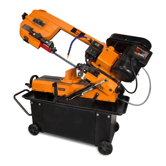
7" x 12"
BAND SAW
Model # 39707
(M-F 8AM-5PM CST)
bit.ly/wenvideo
Advertisement
Table of Contents

Related Manuals for Wen 39707


Summary of Contents for Wen 39707
- Page 1 WENPRODUCTS.COM IMPORTANT: Your new tool has been engineered and manufactured to WEN’s highest standards for dependability, ease of operation, and operator safety. When properly cared for, this product will supply you years of rugged, trouble-free performance. Pay close attention to the rules for safe operation, warnings, and cautions. If you use your tool properly and for its intended purpose, you will enjoy years of safe, reliable service.
-
Page 2: Product Specifications
Assembly Preparation & Adjustments Operation Maintenance Exploded View & Parts List Warranty Statement PRODUCT SPECIFICATIONS Model Number: 39707 Motor: 120V, 60 Hz, 9.5A, Single Phase, Class B Motor Speed: 1700 RPM Blade Speed: 135, 160, 230, 390 FPM Blade Size: 93 x 3/4 x 0.032 in. -
Page 3: Safety Introduction
SAFETY INTRODUCTION Thanks for purchasing the WEN Metal Band Saw. This is an exciting moment. You have received your new tool, opened the box, and are now about to read through the instruction manual. This manual provides information regarding potential safety concerns, as well as helpful assembly and operating instructions. Safe operation of this tool requires that you read and understand this operator’s manual and all labels affixed to the tool. -
Page 4: General Safety Rules
GENERAL SAFETY RULES WARNING! Read all safety warnings and instructions. Failure to follow all instructions may result in electric shock, fire and serious injury. The term “power tool” in the warnings refers to your mains- operated (corded) power tool. Save all warnings and instructions for future reference. WORK AREA SAFETY 1. -
Page 5: California Proposition 65 Warning
GENERAL SAFETY RULES 5. Do not overreach. Keep proper footing and balance at all times. This enables better control of the power tool in unexpected situations. 6. Dress properly. Do not wear loose clothing or jewelry. Keep your hair, clothing and gloves away from moving parts. -
Page 6: Machine Safety
SPECIFIC RULES FOR METAL BAND SAWS This metal band saw is designed and intended for use by properly trained and experienced personnel only. If you are not familiar with the proper and safe operation of a metal band saw, do not use it until proper training and knowledge have been acquired. -
Page 7: Grounding Instructions
ELECTRICAL INFORMATION GROUNDING INSTRUCTIONS In the event of a malfunction or breakdown, grounding provides the path of least resistance for an electric current and reduces the risk of electric shock. This tool is equipped with an electric cord that has an equipment grounding conductor and a grounding plug. -
Page 8: Packing List
KNOW YOUR METAL BAND SAW Carefully remove the tool and all contents from the packaging. Check all components and compare against the diagram below. If any part is damaged or missing, please contact our customer service at (800) 232-1195, M-F 8-5 CST or email us at techsupport@wenproducts.com. -
Page 9: Unpacking The Machine
ASSEMBLY WARNING: To prevent injury from accidental operation, make sure the tool is switched OFF and un- plugged from the power source before assembling the tool or making any adjustments. UNPACKING THE MACHINE WARNING: This big boy is very heavy, so you will need a muscular friend (or a trustworthy foe) to help you lift and assemble the machine. -
Page 10: Coolant Tank Preparation
ASSEMBLY WARNING: To prevent injury from accidental operation, make sure the tool is switched OFF and un- plugged from the power source before assembling the tool or making any adjustments. INSTALLING THE HYDRAULIC CYLINDER 1. Insert the hydraulic cylinder support rod (Fig. 3 - 1) into the saw base. - Page 11 PREPARATION & ADJUSTMENTS WARNING: To prevent injury from accidental operation, switch OFF and unplug the tool before making any adjustments. CONTROLLING THE HYDRAULIC SYSTEM The hydraulic system is used to control the blade’s feed rate and to lock the saw arm in the raised position. The hydraulic lever (Fig.
-
Page 12: Adjusting The Vise
PREPARATION & ADJUSTMENTS WARNING: To prevent injury from accidental operation, switch OFF and unplugged the tool before making any adjustments. ADJUSTING THE VISE The position and angle (0 to 45 degrees) of the vise can be adjusted to securely hold your workpiece in place. To adjust the position of the left movable jaw: 1. -
Page 13: Squaring The Blade To The Table
PREPARATION & ADJUSTMENTS WARNING: To prevent injury from accidental operation, switch OFF and unplugged the tool before making any adjustments. SQUARING THE BLADE TO THE TABLE 1. Raise the saw arm slightly and turn OFF the hydrau- lic valve to lock the saw arm in place. 2. -
Page 14: Adjusting The Blade Guide Bearings
PREPARATION & ADJUSTMENTS WARNING: To prevent injury from accidental operation, switch OFF and unplugged the tool before making any adjustments. ADJUSTING THE BLADE GUIDE BEARINGS WARNING: Saw blades are sharp. Wear Side Guide work gloves when handling saw blades to Bearings prevent injuries. -
Page 15: Prior To Operation
OPERATION WARNING: To prevent serious injury, make sure all the warnings and instructions have been read and understood before operating this tool. PRIOR TO OPERATION 1. Check the workpiece: • The workpiece is within the cutting capacity of the saw. Cutting capacity @ 90 degrees: 7 in. -
Page 16: Operating The Saw
OPERATION ON/OFF SWITCH & AUTOMATIC SHUTOFF Press the green button (I) (Fig. 23 - 1) to turn ON the motor. Wait for the blade to reach full speed before allowing the blade to enter the workpiece. This machine has an automatic shutoff function that will stop the motor when the saw arm has come down to the horizontal position. -
Page 17: General Maintenance
MAINTENANCE WARNING: Disconnect the machine from the power source before making any maintenance or adjust- ments. Failure to do so may result in serious injury. GENERAL MAINTENANCE 1. Keep all surfaces clean and free of rust, chips and coolant buildup. At the end of each work day, vacuum sawdust and clean the machine with a dry cloth or brush. -
Page 18: Changing The Saw Blade
MAINTENANCE WARNING: The blade is sharp and springy. Make sure to wear work gloves and safety glasses. The blade may bounce back and hit you during installation. Wear long work pants and long sleeve shirt to protect yourself from injuries. CHANGING THE SAW BLADE NOTE: The machine is designed to be used with blades that are 93"... - Page 19 MAINTENANCE CHANGING THE SAW BLADE (CONT.) 9. Carefully wrap the blade around the bottom wheel (Fig. 29 - 2). Hold the blade around the bottom wheel with one hand and slip it around the top wheel with the other hand, keeping the blade between the blade guide bearings.
-
Page 20: Adjusting The Blade Tracking
MAINTENANCE ADJUSTING THE BLADE TRACKING WARNING: Blade tracking adjustment requires running the saw with the back cover open. This adjust- ment must only be completed by a qualified person. Failure to comply may cause serious injury. Blade tracking has been set at the factory and should not require adjustment on your existing blade. If a tracking problem occurs, before making any tracking adjustments, try replacing with a new blade (see page 20 “Changing the Saw Blade”) and see if the tracking issue is resolved. -
Page 21: Product Disposal
Fig. 34 Replace the wire brush assembly (Part No. 39707-204) if it becomes damaged or worn out. The blade life will be greatly shortened if the blade cleaning brush is out of adjustment, becomes damaged or becomes worn out. -
Page 22: Exploded View And Parts List
EXPLODED VIEW & PARTS LIST... - Page 23 EXPLODED VIEW & PARTS LIST...
- Page 24 Support Plate, Right 39707-060 Hex Nut M10 39707-023 Spring 39707-062 Limit Switch 39707-024 Spring Adjusting Rod 62-3 39707-062-3 Spring Washer M6 39707-025 Spring Handle Bracket 62-4 39707-062-4 Washer M6 39707-026 Hex Hd Screw M8x16 62-5 39707-062-5 Round Hd Screw M6x16...
- Page 25 Hex Hd Screw M10x40 39707-082 Hydraulic Cylinder 39707-121 C-Ring 39707-083 Washer M8 39707-122 Blade Wheel (Rear) 39707-084 Hex Hd Screw M8x25 122-1 39707-122-1 Saw Wheel Bushing 39707-085 Hex Hd Screw 39707-123 Hex Bolt M8x20 39707-087 Cylinder Bracket 39707-124 Pin 4X25 39707-088...
- Page 26 EXPLODED VIEW & PARTS LIST Part No. Description Part No. Description 39707-145 Round Hd Screw M6x16 39707-174 Motor Pulley Cover 145-1 39707-145-1 Spring Washer 6 39707-176 Washer M6 Coolant Valve Support 39707-177 Hex Hd Screw M6x16 39707-146 Bracket 39707-178 Key 6X6x40...
-
Page 27: Limited Two-Year Warranty
LIMITED TWO YEAR WARRANTY WEN Products is committed to build tools that are dependable for years. Our warranties are consistent with this commitment and our dedication to quality. LIMITED WARRANTY OF WEN CONSUMER POWER TOOLS PRODUCTS FOR HOME USE GREAT LAKES TECHNOLOGIES, LLC (“Seller”) warrants to the original purchaser only, that all WEN con- sumer power tools will be free from defects in material or workmanship for a period of two (2) years from date of purchase. - Page 28 THANKS FOR REMEMBERING...
Need help?
Do you have a question about the 39707 and is the answer not in the manual?
Questions and answers