
Summary of Contents for FACTS Engineering Direct Logic 405
- Page 1 Automationdirect.com™ D i r e c t L o g i c 4 0 5 F o u r L o o p T e m p e r a t u r e C o n t r o l l e r F 4 - 4 L T C Manual Order Number: F4-4LTC-M...
- Page 3 ™CoProcessor is a Trademark of FACTS Engineering, Inc. COPYRIGHT Copyright 1994, FACTS Engineering Inc., 8049 Photonics Dr., New Port Richey, Florida, 34655. World rights reserved. No part of this publication may be stored in a retrieval system, transmitted, or reproduced in any way, including but not limited to photocopy photograph, magnetic or other recording media, without the prior agreement and written permission of FACTS Engineering, Inc.
- Page 5 Features may be described herein which are not present in all hardware and software systems. FACTS Engineering assumes no obligation of notice to holders of this document with respect to changes subsequently made. FACTS Engineering retains the right to make changes to hardware and software at any time, without notice.
-
Page 7: Table Of Contents
TABLE OF CONTENTS CHAPTER 1: INTRODUCTION ........... . 1.1 GENERAL DESCRIPTION . - Page 8 TEMPERATURE CONTROL PARAMETER DESCRIPTIONS ..... . . 2.13 Bit Mapped Mode Word (V5000) ........2.13 Usage of Mode Bits .
- Page 9 APPENDIX A: PID FUNDAMENTALS ..........5.1 PID CONTROL FUNDAMENTALS .
-
Page 11: Chapter 1: Introduction
CHAPTER 1: INTRODUCTION GENERAL DESCRIPTION The Direct Logic 405 Four Loop Temperature Controller CoProcessor integrates into one single slot module, all the functions of four, single loop temperature controllers. Because the module uses the DL405 high speed parallel dual port RAM interface, the effect on CPU scan time is minimal. -
Page 12: Alarming And Diagnostics
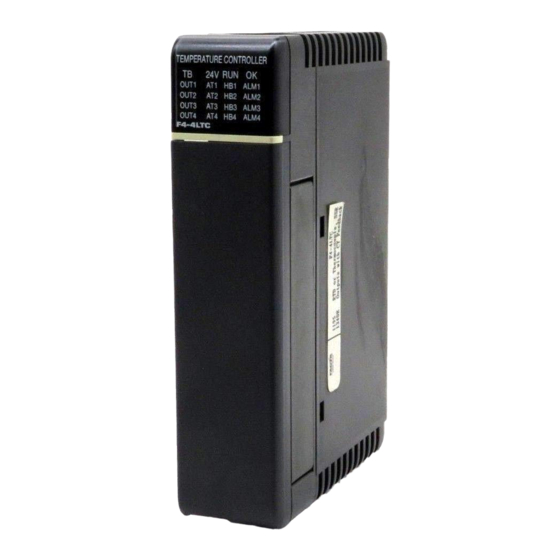
ALARMING AND DIAGNOSTICS LEDs The 20 LEDs on the face of the module provide a quick indication of the operating status of all four temperature loops. An LED is provided for each loop to indicate when an Output is ON, Auto Tune is ON, an Alarm condition is present or when heater burn-out has been detected. -
Page 13: Operational Specifications
OPERATIONAL SPECIFICATIONS Installation Up to 8 Temperature Controllers may be used with a single 405 CPU. Temperature Controllers must be installed in the CPU base. V-Memory A slot dependent V-Memory location specifies the starting address of the block of Block V-Memory to be used by the Temperature Controller. -
Page 14: Temperature Controller Hardware Specifications
TEMPERATURE CONTROLLER HARDWARE SPECIFICATIONS General Specifications Number of Loops Input Type Differential Common Mode Range ± 5 Vdc Converter Type Charge Balancing, 24-bit Controller Output Open collector, 5 to 50 Vdc at .15A. Notch Filter > 100 db notches at 50 Hz and 60 Hz f-3db = 13.1 Hz Common-Mode Rejection 90 db minimum at DC... -
Page 15: Voltage Input Specifications
Voltage Input Specifications Voltage Ranges 0-5, ±5V, 0-156.25, ±156.25mV Resolution 16-bit binary (1 in 65536) Calibration Error ±13 counts typ., ±33 maximum full scale ±1 count maximum offset (0V input) Maximum Inaccuracy ±.02% typ. ±.2% maximum Thermocouple Input Specifications Type J -190/760 EC (-310/1400 EF) Temperature Ranges Type E -210/1000 EC (-346/1832 EF) Type K -150/1372 EC (-238/2502 EF) - Page 16 INTRODUCTION...
-
Page 17: Chapter 2: Installation And Wiring
CHAPTER 2: INSTALLATION AND WIRING STEPS FOR F4-4LTC INSTALLATION The following steps should be used as guideline for installation of the F4-4LTC. All steps may not be necessary in all applications. Set Jumpers for RTD or Thermocouple Install F4-4LTC in the CPU Base and Note the Slot Number Connect Temperature Sensors to TEMP Inputs Connect SSR Controller Outputs to SSRs Connect CT Inputs to Current Transformers... -
Page 18: Set Configuration Jumpers
SET CONFIGURATION JUMPERS The module should be jumpered for the type of input device that it will be connected to. Use the following diagrams to configure the jumpers on your module. The two configurations shown here are the only valid settings, any other settings may cause unpredictable results. RTD Inputs Voltage or Thermocouple Inputs UNUSED TEMPERATURE INPUTS... -
Page 19: Install F4-4Ltc In Cpu Base
INSTALL F4-4LTC IN CPU BASE There can be up to 8 Four Loop Temperature Controllers per system. The temperature controller must be installed in the CPU base. LED STATUS INDICATORS On when I/O terminal block is loose or missing. On if no external 24 VDC power or if analog circuit failed. -
Page 20: Rtd Connection Diagram
RTD CONNECTION DIAGRAM Notes: Accurate lead wire compensation requires that the three wires which connect an RTD to the Controller be exactly the same resistance (a 3.7' difference in 26 AWG lead length will introduce a .2 EF error). If a four wire RTD is used, leave unconnected one of the positive side leads (only one wire should be connected to TEMP+). -
Page 21: Thermocouple Connection Diagram
THERMOCOUPLE CONNECTION DIAGRAM Notes: Ground the shield drain wire at one end only. For grounded thermocouples, connect shield at the sensor end. For ungrounded thermocouples, connect shield to the COM terminal of the F4-4LTC Temperature Controller module. COM and 0 VDC are internally connected. Observe the warning on page 2.2. INSTALLATION AND WIRING... -
Page 22: Grounded Vs Ungrounded Thermocouples
GROUNDED VS UNGROUNDED THERMOCOUPLES Grounded Thermocouple Assembly A grounded thermocouple provides better response time than an ungrounded thermocouple because the tip of the thermocouple junction is in direct contact with the protective case. Ungrounded Thermocouple Assembly An ungrounded thermocouple is electrically isolated from the protective case. If the case is electrically grounded (for example, by the conduit) it provides a low impedance path for electrical noise to travel. -
Page 23: Maximizing Thermocouple Measurement Precision
MAXIMIZING THERMOCOUPLE MEASUREMENT PRECISION Ambient Temperature Variations The FACTS Engineering Temperature Controller module has been designed and tested to operate within specifications over a 0 to 60 EC ambient temperature range. Thermocouple cold junction compensation is calibrated for operation in a still air environment. If used in an application with forced convection cooling (such as an enclosure with air circulated by a fan) then 2-3 EC of error is typically introduced into the cold junction compensation circuit. -
Page 24: Dedicated V-Memory Map
DEDICATED V-MEMORY MAP Each Temperature Controller has three dedicated V-Memory locations associated with it to specify the starting address of the Temperature Controller Parameters table, the number of temperature control loops enabled (scanned) for that module, and a location for the module to return configuration and self diagnostic error flags. -
Page 25: Operating Mode And Loops Enabled
Operating Mode and Loops Enabled The Operating Mode and Loops Enabled location programs the operating mode and the number of loops enabled for the module. The most significant byte selects the Operating Mode and the least significant byte selects the number of Loops Enabled. Operating Mode There are four possible operating modes for all the enabled loops on the controller. -
Page 26: Error Flag
Error Flag The dedicated V-Memory Error location for each Controller is used to report configuration and diagnostic errors. This location is bit mapped. If any one of the fatal errors is detected at power up, the TB and 24V LEDs will flash back and forth until the error is cleared. Hexadecimal Weight Bit Number Bit Description... -
Page 27: Temperature Controller Loop Configuration Memory
TEMPERATURE CONTROLLER LOOP CONFIGURATION MEMORY All V-Memory values are in hexadecimal. Use the DirectSoft BCD/Hex or Binary data type to monitor loop bit mapped values, use decimal data type to display or monitor all other loop V-Memory values. NOTE: The DirectSoft decimal data type will convert a hexadecimal value, 0-0FFFFH, to it's decimal equivalent, 0-65535. -
Page 28: Temperature Controller Loop Configuration Memory Map, 1 Loop
TEMPERATURE CONTROLLER LOOP CONFIGURATION MEMORY MAP, 1 LOOP Decimal Offset Example V-Mem. Description Units 0-1 Read continually V5000 Mode Word bit mapped ± 3276.7 EC/EF V5001 Temperature Setpoint V5002 Output Bias 0.0-100.0% or 0-4095 3-5, Written after each temperature acquisition V5003 Output 0.0-100.0% or 0-4095... -
Page 29: Bit Mapped Mode Word (V5000)
TEMPERATURE CONTROL PARAMETER DESCRIPTIONS Bit Mapped Mode Word (V5000) The bit mapped Mode Word allows you to enable and disable features, enter new PID parameters, enter new Alarm Parameters, and specify the format of the output word. There is one Mode Word per loop so that each loop can be programmed independently. -
Page 30: Temperature Setpoint (V5001)
Usage of Mode Bits Turn on bit 0 whenever any of the PID or alarm setup parameters are changed. The Temperature Controller automatically clears this bit after the new setup parameters have been loaded. Turn off bit 1 if heating control action is required. This will cause the output to increase when the temperature is below the SetPoint. -
Page 31: Output Bias (V5002)
Output Bias (V5002) Output Bias or Manual Reset is the result of the integral control action of the PID Temperature Controller. It is the integral of the error over time and is added to the Output (V5003). Bias accommodates SetPoint and load changes by eliminating steady state errors. It is sometimes called automatic reset. -
Page 32: Bit Mapped Alarm Word (V5004)
Bit Mapped Alarm Word (V5004) The bit mapped Alarm Word reports the status of the programmed alarms, the temperature sensor, and the built-in output. It is written to by the temperature controller after each temperature acquisition. Hexadecimal Weight Bit Number Bit Description 0001 ON = Temperature Low Alarm... -
Page 33: Gain (V5006)
Gain (V5006) Gain specifies the Proportional value used in the PID control algorithm. Some temperature controllers have a proportional band adjustment instead of a Gain adjustment. Gain is the inverse function of the proportional band. This means that the gain settings of 5, 1, and .5 would be equal to the proportional band settings of 20, 100 and 200% of temperature span. -
Page 34: Temperature High Alarm (V5012)
Temperature High Alarm (V5012) The Temperature High Alarm occurs when the temperature rises above the value programmed in this location. This value is read by the temperature controller when bit 0 of the Mode Word is set. Temperature Deviation Alarm (V5013) The Temperature Deviation Alarm occurs when the temperature is further from the SetPoint than the value programmed in this location. -
Page 35: Input Type (V5017)
Input Type (V5017) Input Type specifies the temperature or voltage input device being used. This parameter is used in conjunction with the module jumper settings described on page 2.2. RTDs, Voltage Inputs or Thermocouples cannot be mixed on the same module. Any combination of thermocouple types K, J, E, and N may be used. -
Page 36: Pid Control Period (V5020)
PID Control Period (V5020) The PID Control Period specifies the time period that the output will be applied to. This value is also used as the sample rate for the PID calculation. It is read by the temperature controller when bit 0 of the Mode Word is set and only applies to PID control. -
Page 37: Temperature Calibration Adjustment (V5022)
Temperature Calibration Adjustment (V5022) Temperature Calibration Adjustment is a ± 3276.7 EC or EF value which is added to the controller measured Process Temperature. This location can be used to remove inaccuracies due to thermocouple cold junction compensation errors (see page 2.7) and temperature input device errors (typical thermocouple device inaccuracy is ±1 to ±3 EC). - Page 38 2.22 INSTALLATION AND WIRING...
-
Page 39: Chapter 3: Supporting Ladder Logic
CHAPTER 3: SUPPORTING LADDER LOGIC Minimal or no ladder logic is required in most applications. The following ladder logic examples extend the capabilities of the Temperature Controller. SLOT DEPENDENT CONFIGURATION The rung below programs the slot dependent V-Memory locations for a F4-4LTC in Slot 4, Normal Operating Mode, and 4 Loops Enabled. -
Page 40: Alarm Word Decoding
ALARM WORD DECODING The rung below copies the alarm bits for loop 1 (V5004) into Y0-Y4. Temperature Low Alarm Temperature High Alarm Temperature Deviation Limit Alarm Broken RTD or Thermocouple (Burn-out detected) No Heater Current Alarm (open or disconnected) ALARM WORD ENCODING Some operator interface software packages do not permit examining discrete bits in user V-Memory. -
Page 41: Force Output On/Off (Manual Over-Ride)
FORCE OUTPUT ON/OFF (MANUAL OVER-RIDE) The following example uses two contacts to implement manual over-ride. X10 is used as a selector switch, if it is OFF then manual over-ride is disabled if it is ON then manual over-ride is enabled. If X10 is ON then X11 selects which state to force the output, X11 OFF forces the output OFF, X11 ON forces the output ON. -
Page 42: Discrete Output Status
DISCRETE OUTPUT STATUS The status of the discrete time proportioned solid state relay outputs built into the Temperature Controller is also written to bit 15 of the Alarm Word. This allows you to use an AC Output or High Current Relay Output module in the PLC to directly control, for example, a heater. -
Page 43: Positioning Actuator Control Loops
POSITIONING ACTUATOR CONTROL LOOPS A reversible electric motor used to operate a valve is an example of a positioning actuator. This example will use the controller output in V5003 to position an actuator controlled by forward and reverse contacts. Y11 will run the motor in reverse and Y10 will turn the motor in the forward direction. Feedback is required to correctly position the actuator. -
Page 44: Setpoint Ramp And Soak
SETPOINT RAMP AND SOAK For each loop the user can program a Ramp or Soak of the SetPoint as shown in the following examples. SetPoint Ramp A ramp of the SetPoint is the changing from the current SetPoint to a specified final SetPoint over a specified period of time. - Page 45 SUPPORTING LADDER LOGIC...
-
Page 46: Setpoint Soak
SetPoint Soak A Soak of the SetPoint is the changing from the current SetPoint to a specified final SetPoint in specified steps with each step maintained for a specified time. If guaranteed soaking is programmed, at each step change in the SetPoint, the Process Variable must be within a specified band around the SetPoint in order for the Soak time to be measured. - Page 47 SUPPORTING LADDER LOGIC...
- Page 48 3.10 SUPPORTING LADDER LOGIC...
-
Page 49: Chapter 4: Loop Tuning
CHAPTER 4: LOOP TUNING AUTO TUNE PROCEDURE Configure the module for the type of Temperature Sensor (V5017). Then program the PID Control Period (V5020) and Temperature SetPoint (V5001). The default value for the PID Control Period of two seconds (V5020=20) is sufficient for most applications. -
Page 50: Auto Tune Sequence
AUTO TUNE SEQUENCE The auto tune algorithm uses the following sequence of operation to calculate the controller settings. The state of the auto tune operation is reported by the Auto Tune Sequence Status bits A and B located in the Alarm Word (V5004). Bring the temperature to within 1.0 EC (1.8 EF) of the SetPoint. - Page 51 Problem: Auto Tune "hangs up" during Auto Tune Sequence steps 1, 2, or 3 and never finishes. Cause 1: One degree C of temperature instability due to noise pickup will prevent Auto Tune from completing successfully. Solution 1: Possible solutions to this problem are: Improve sensor wiring, shielding, and grounding and re-tune the loop.
-
Page 52: Auto Tune Optimization
AUTO TUNE OPTIMIZATION A perfectly tuned loop will respond quickly with no overshoot. This is the Auto Tune goal. However, the auto tune algorithm cannot determine the perfect controller settings for every application. Manual optimization can be used to fine tune the controller settings for each application. For example, fine tuning can be used to increase response, minimize steady state errors, or reduce overshoots. -
Page 53: Manual Pid Tuning
MANUAL PID TUNING Some applications will require manual PID tuning. First time PID control user's should review the PID Fundamentals described in Appendix A. Also review Auto Tune Optimization above to gain an understanding of the effect that Gain and Reset have on the PID controller. Configure the module for the type of Temperature Sensor (V5017). - Page 54 Calculate the controller settings given the ultimate gain and period determined in step 7. Gain (V5006) = .6Ku Reset (V5007) = .5Pu Rate (V5010) = Pu/8 For example, if the ultimate period is 140 seconds then the Reset value is 70 and the Rate value is 17.
-
Page 55: Appendix A: Pid Fundamentals
PV due to noise or other sources cause the output to become unstable. The FACTS Engineering Temperature Controller uses a proprietary Derivative Control action filter which de-glitches the PV while at the same time retaining the full effect of the rate setting. For correctly tuned loops, this method results in a lower damping ratio than a comparable controller with derivative gain limiting. -
Page 56: Loop Operating Modes
LOOP OPERATING MODES The Temperature Controller operates in one of two modes, either PID or ON/OFF control. PID Control In PID Control mode, the Temperature Controller initially computes and controls the outputs based on the programmed PID parameters stored in V-Memory. These parameters are normally calculated during the Auto Tuning process. -
Page 57: Pid Equation
PID equation The Temperature Controller approximates the output M(t) using a discrete PID equation. Ts = Sample rate. Kc = Proportional gain. Ki = Kc * (Ts / Ti) = Coefficient of the integral term Kr = Kc * (Td / Ts) = Coefficient of the derivative term Ti = Reset or integral time. -
Page 58: Reverse Acting Loop (Cooling)
Reverse Acting Loop (Cooling) The Temperature Controller allows a loop to be programmed as reverse acting. With a reverse acting loop, the output is driven in the opposite direction of the error. For example, if SP>PV then a reverse acting controller will decrease output to increase the PV. = −... -
Page 59: Appendix B: Troubleshooting
APPENDIX B: TROUBLESHOOTING If the module is not operating as expected then use this appendix to get the module up and running quickly. First review the description of normal module operation. If this does not identify the problem then scan the following frequently asked questions plus solutions to common problems. - Page 60 Problem: The temperature always reads 3276.7 degrees. Cause 1: The module is not jumpered correctly for the type of input device. See page 2.2 for module jumper settings. Solution 1: Jumper the module correctly. Cause 2: The Input Type location does not have the correct code for the type of input device that is connected.
- Page 61 Cause: These values are only read when module powers up. Solution: Power cycle the module. Problem: I changed my alarm parameters but the new values don't seem to be used. Cause: These values are only read when bit 0 of the Mode Word is set. Solution: Set bit 0 of the Mode Word (see the example on page 3.1).
- Page 62 TROUBLESHOOTING...
Need help?
Do you have a question about the Direct Logic 405 and is the answer not in the manual?
Questions and answers