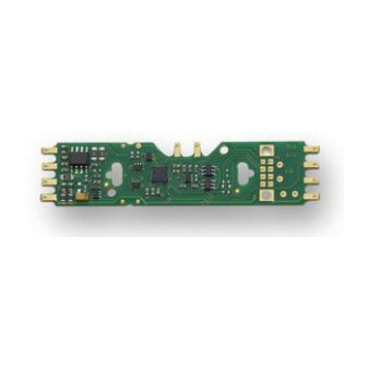
N scale mobile decoder 1.0 amp/1.5 amp peak 2 functions, 0.5 amp dcc plug 'n play with 1' harness, fits many dcc-ready n and ho scale locomotives (3 pages)
Page 1
Mobile & Sound Decoder Manual Second Edition Includes: Digitrax Series 3, 4, 5 & 6 Mobile, Sound & Function Decoders Digitrax, Inc. 2443 Transmitter Road Panama City, Florida 32404 www.digitrax.com Digitrax Manuals & Instructions are updated periodically.
3.3.3 Which Decoder Will Fit? ..........11 3.3.4 Decoder Interfaces for Installation ......12 3.3.4.1 Plug ‘N Play and Board Replacement Interfaces ...12 3.3.4.2 Digitrax 9 Pin HO & 8 Pin N Decoder Interfaces ..14 3.3.4.3 Installing Decoders with Wires ........14 3.3.5 Decoder Features-LocoMotion ........16 3.3.6 Decoder Functions-Lights, Sound, Etc.
Page 3
8.7.2 LED/Lamp Algorithm Selector ........51 8.7.3 CV61 Values: Transponding & Lighting Algorithm ..51 8.8 CV09 SuperSonic (Quiet Operation) ........52 9.0 Function CVs ............9.1 Digitrax Light Effects: CV49-CV52 & CV113-CV116..52 9.2 Setting Up FX Effects On Function Outputs ....52 9.3 Commonly Used FX Effects On Function Outputs ..53...
Page 5
This manual may not be reproduced in any form or translated without written permission from Digitrax. Digitrax, Inc. reserves the right to make changes in design and specifications, and/or to make changes, additions and/or improvements in its products without any obligation to install these changes, additions and/or improvements on prod- ucts previously manufactured.
FX 3 effects, analog mode conversion, speed stabi- lization, transponding and more. Digitrax offers many decoders that are simple to install however, in some cases decoder installations are more challenging. Most model railroaders have the common sense, judgment and skills needed to successfully install decoders.
5 and 6 Digitrax decoders. This Mobile Decoder Manual and all Decoder Instruction Sheets are available at www.digitrax.com. In addition, the first edition of the Digitrax Mobile Decoder Manual is available at www.digitrax. com for pre-Series 4 decoders that are no longer in production.
Page 8
Series 5 decoders are capable of hosting Sound Bug add-on sound decoders. Series 6 decoders have optimized LED and lamp lighting algorithms, have improved scaleable speed stabilization (Back EMF), work with Digitrax Power Xtenders to improve performance in the presence of power interruptions and have configurable FX 3 pulse function on all function outputs.
3.0 Decoder Installation Each Digitrax decoder comes with an instruction sheet that shows you the spe- cifics of how to install it in a locomotive. There are also additional installation application notes and installation videos available at www.digitrax.com/sup- port.
Decide where the decoder will fit inside the loco. Is there space to put the decoder or will you need to “make room?” Is there a decoder made specifi- cally for the loco? Digitrax offers a variety of decoder sizes, form factors and current ratings to accommodate almost any locomotive. Check the Decoder Selector at www.digitrax.com for a list of recommendations.
In many cases for O, S, O-27 & G scale Digitrax 3, 4, or 5 amp decoders will the best choice. If your installation has 2 or more motors, you will need to consider the stall currents for both motors to determine the best decoder to use.
For installations in small spaces, Z and N scale decoders are rated at 1 amp or more and will work fine in HO scale locomotives. The Digitrax Tech Support Depot at www.digitrax.com/support, has links to application notes and videos for installations in many different locomotives.
Page 13
N Scale where the decoder body will be near the socket. Digitrax 9 Pin HO: The Digitrax 9 pin socket & plug is another commonly used DCC plug ‘n play interface that is available in some HO locos.
3.3.4.2 Digitrax 9 Pin HO & 8 Pin N Decoder Interfaces Some Digitrax HO & N scale decoders come with a plug and socket on the decoder so that the wire harness can be unplugged from the decoder. This inter-...
Page 15
Refer to TABLE II for Digitrax Mobile Decoder Standard for Wire Colors and Figure 1 Digitrax Decoder Wiring Diagram for general instructions and the specific Decoder Instruction Sheet that came with your decoder for specific instructions for the decoder you are installing. See Figure 2 for lamp installa- tion information.
All Digitrax decoders are equipped with two or more function outputs that are used to turn functions on and off and set up special lighting effects called FX 3 .
Functions associated with advanced consists can be controlled, too. Function outputs on Digitrax decoders are available in several current ratings depending on the decoder. These ratings are the total current available for activating and running the devices attached to ALL the function outputs on the decoder.
3.7 Testing Decoders Before Installation Digitrax tests each decoder prior to shipping. That said, we strongly recom- mend testing by the installer before installation. The test procedure shows you how the decoder works and how to hook up the wires. Testing verifies that the decoder is working before you install it in a loco.
Page 19
Note: The LT1 can also be used to test LocoNet Cables by plugging in one end of the cable being tested into the LT1 and the other end into your command station or booster. At least one Digitrax throttle or Zephyr all-in-one unit must be plugged in to LocoNet. If all four LEDs light, the cable is good.
3.11 Installing Power Xtenders Digitrax Power Xtenders are available for most Series 6 decoders. They are designed to keep locomotives running and sound from dropping out in situations where power to the locomotive is interrupted due to dirty, dead or bad track.
Digitrax recommends running your command station and boosters at the lowest track voltage possible that provides acceptable operation. The “N” (12V) setting on Digitrax command stations and boosters works well for most HO & N scale layouts. The “HO” setting should be used only for HO and larger scales.
These are always available. If you can’t get it to work the way you think it should, let us know! Often your local Digitrax deal- er will be able to help you work out any problems you may encounter. If not, please contact Digitrax directly.
5.1 What are Configuration Variables (CVs)? Each Configuration Variable, CV, controls one or more operating character- istics of the decoder based on the CV value that you program. All Digitrax decoders come with default settings from the factory that will run “out of the box.”...
Another programming option is to use a PR3 Xtra programmer and your com- puter to program and read back decoders. Other DCC compatible programmers are able to program Digitrax decoders as well. Consult the manual for the sys- tem you are using for complete programming instructions.
At first glance, you will see that there are many different CVs. This may seem confusing but, don’t worry, Digitrax decoders are shipped with a set of pre- programmed factory default values that let you get up and running right away.
Page 31
Visit our online CV Calculator at www.digitrax.com/support/cv/ for help with determining the best CV Value to program into a CV. Table III: CVs used in Digitrax Decoders CV Usage/Notes Default Value Value Range Basic Decoder Set Up CVs Locomotive Address CVs...
Ad2 for two digit addresses and Ad4 for four digit addresses. All other CVs are displayed as numbers on Digitrax throttles. Be sure that CV29 is programmed to a value that enables 2 digit operation. See CV29 below for more information.
If your command station sends advanced 28/128 speed step commands, your decoders must be programmed for advanced mode. All Digitrax decoders are 128 speed step capable and we recommend that for best performance you run them in 128 speed step mode. If you are using non-Digitrax decoders that do not support advanced mode and you want to run your command station in advanced mode, you can “status edit”...
Page 39
Most common values for CV29: All Digitrax decoders are shipped with a factory default value of 006 in CV29. This gives the following characteristics to the decoder: 2 digit address, normal direction of travel is forward, 28/128 speed step operation, analog mode con- version ON, loadable speed table OFF.
The shape of this curve defines the “feel” of the decoder’s throttle response. With Digitrax FX 3 decoders, when the loadable speed table is active and 128 speed step information is received from the command station, the table is inter- polated to generate 4 in-between steps to give full 128 step resolution.
“straight-line” throttle response curve is used. The value of 255 represents 100% motor voltage. Digitrax Series 3, 4, 5 & 6 decoders use V-start in 128 speed step mode and run loadable speed tables in 128 speed step mode.
8.3 High Res 28 Step Loadable Speed Tables CV65-95 For a more precise throttle response curve, Digitrax decoders also have avail- able a 28 step loadable speed table option. With this method, you must program values for up to 32 different CVs as detailed below. This can be time consum- ing but you only have to do it once, since the settings will be remembered by the decoder until you change them.
It allows you to run locomotives at the same speed no matter the track grade. It can also help improve operation of steam locomo- tives. Digitrax decoders offer the ability to adjust the amount of speed stabili- zation used by a decoder. Digitrax FX decoders are shipped with default speed stabilization values that improve the operation of most locomotives.
NOTE: Locos must be selected in the system for transponding to work. 8.7.2 LED/Lamp Algorithm Selector Beginning with Series 6 decoders, Digitrax FX effects are optimized for either LEDs or incandescent lamps. Since these two types of lighting devices have different characteristics, Digitrax has set up two selectable algorithms for operating the devices.
9.0 Function CVs Function CVs control how the function leads on your decoder work. 9.1 Digitrax Light Effects: CV49-CV52 & CV113-CV116 Decoders with FX features have 8 user configurable, independent special effects generators. These are set up by programming CV values as described below.
We recommend that you try these first. Then if you want to do more customization to your specific installation you can use our online CV calculator at www.digitrax.com/support/ cv to compute the CV values for your specific situation.
F2 turned off by releasing the key on the throttle. Remember that F2 is a momentary key on most Digitrax throttles that will keep Function 2 on as long as you hold the key down and then turn Function 2 off when you release the key.
Trying to program a decoder for FX when the decoder does not sup- port FX. Be sure the decoder you are installing has FX features. Digitrax introduced FX in the summer of 1995 so if your decoder was made before then it does not have FX capability. Since 1995 all Digitrax premium decoders have included FX.
CVs. To make all CVs be controlled by the advanced consist address, pro- gram a value of 255 to both CV21 & CV22. Visit www.digitrax.com/support/ cv/ for our automated CV value calculator.
CV15 and CV16. Decoder Lock is a manufacturer specific CV. The instructions provided here are for Digitrax decoders. If you are using decoders from another manufactur- er, please consult your decoder’s instructions for how this feature works with the decoder you have installed.
Page 67
When the values in CV15 and CV16 are not equal, only CV15 can be pro- grammed. CV54 allows decoder lock to be disabled. Digitrax decoders are shipped with decoder lock enabled by default. The Factory Default Reset CV (CV08=08) will not work on decoders that are locked unless the CV15 and CV16 values are equal.
CV07 is the version ID. This is a read only CV that can’t be changed. CV08 is the decoder reset CV which also contains the manufacturer ID. The manufacturer ID is read only and can’t be changed. 11.0 Digitrax SoundFX System ® Digitrax SoundFX decoders come “ready to run”...
11.1.1 Speaker and Baffle Installation The sound performance of any sound decoder depends on the speaker(s), how it is installed and the baffle or rear enclosure. Your Digitrax SoundFX decoder was equipped with speaker at the factory. You may choose to use a different speaker as long as it does not exceed the decoder’s specifications.
11.2 Programming SoundFX Decoders Your Digitrax SoundFX decoder is ready to run and will operate and generate sound using address 03 with no additional programming. See the instruction sheet that came with your decoder for information about the default sound scheme and other sound schemes that may be available in the decoder.
CVs are used in the specific decoder and in the specific sound project file. For more information on general decoder installation and programming tech- niques and examples visit www.digitrax.com. CAUTION: Programming track voltage must not exceed 16V when pro- gramming SoundFX decoders.
11.10 Loading Sound Projects into your SoundFX Decoder Your sound decoder’s sound project can be changed using a Digitrax PR3 pro- grammer and your computer with SoundLoader 2.0 software. Both the software and a number of alternate sound project files are available from the Digitrax Sound Depot web site at no charge.
Page 75
Horn=2 +128 for playable volume.) Auto Coupler Sequence Threshold Value-Peak speed to allow 00-64 auto coupler/brake when direction change occurs and F3 is ON Project Author ID, Digitrax=221 Project ID Steam Blow down / Safety Volume 0-64 Notching/Slip Mode: 00=Automatic,...
Steam = Safety Blow off 11.11 SoundFX DC Operation Mode Digitrax SoundFX decoders will operate on smooth DC power. The sound will not start until approximately 7 volts is applied to the track and there will be no “start up sound.”...
If the sound in your decoder shuts down after you stop it and you are not using a Digitrax system for control. On some DCC systems decoders are not addressed by DCC packets after the locomotive is set to 0 speed. In this case after the CV11 timeout elapses (6 second default), sound will “shutdown.”.
Digitrax decoders with the system you are using. If there is still a problem, please check the Tech Support Depot on our website for articles related to the non-Digitrax equipment you are using.
In the event that you need a repair for a decoder or other Digitrax product that is out of warranty we will make every effort repair or replace it for a small charge.
Page 80
Proof of date of purchase is required for all warranty repairs. In some cases with Digitrax lower cost decoders, the cost to purchase a new decoder may be less than the repair charge. Also some older models are no longer repairable or replaceable due to unavailability of components needed for these repairs.
Page 86
& dealer locater. www.digitrax.com/toolbox Warranty and Repairs www.digitrax.com/support/returns Fill out the online form, print it out and return it with your item for repair Your Local Digitrax Dealer Is Also Available to Assist You.
Need help?
Do you have a question about the 3 Series and is the answer not in the manual?
Questions and answers