Advertisement
Quick Links
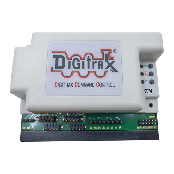
SE74
Features:
▪
4 SE1 Digitrax 10-pin ribbon cables that control 4 LED signal heads each.
▪
4 Switch (SW) control outputs for solenoid or slow-motion turnouts.
▪
Plug-in connectors for simple and easy installation and service.
▪
User defined 4+32 consecutive SW addresses in 2000+ SW range.
▪
Optional 9 types of DCC Aspect control, including Lunar lamps.
▪
Easy setup with Option Switches (OPSW) or LocoNet CV programming.
▪
Power input from 2mm DC jack, or DCC track voltage, 10V min to 20V max.
▪
8 easy to setup System Routes, with 8 SW Entries each.
▪
8 input control lines; 4 for Output/SW change and 4 Sensor/DS inputs.
▪
Additional advanced LocoNet Configuration modes using DT602 throttles.
Parts List
1 SE74 Stationary Decoder
1 Instruction Sheet
1.0 SE74 Quick Start - 4 Turnout control function
1.
Figure 1 shows the recommended connections to operate the SE74 on a Lo-
coNet layout and to control 4 SE1 signal cables with 16 total signal heads and
4 solenoid turnouts.
2.
Connect a PS14 or similar DC 12V power supply to the SE74 via the DC pow-
er jack. When powered the green ID LED should light and will briefly wink
OFF every 2 secs as a product 'heartbeat' showing the SE74 is operational.
Alternatively, power from DCC feeder wires to the TKA/B terminals.
3.
Plug in an active LocoNet to a SE74 RJ12 connector. The red OPS LED will
light up showing connection. Any good LocoNet message seen will cause the
SE74 OPS LED to blink OFF briefly. With no LocoNet the unit will default to
switch commands from the DCC track connections TKA/TKB.
4.
Factory default Base SW# is 253 to control turnout #1. To set to a custom
Base number, press and hold down the ID button for about 3 seconds until
the RTS and OPS LEDs blink alternately, then release the ID button. From
your system send a SW command to set the new Base address at this SW#.
The OPS and RTS LEDs will stop blinking showing the SE74 has set the
unit's Base SW# to the SW# you just sent, which controls SE74 turnout 1.
5.
Wire and plug in 3-wire solenoid turnouts as shown in figure 1. To use 4 stall
type switch motors modify Option Switch (OPSW) 1 to Closed/C, (see section
4.0), and use 2 wires per motor, with no P+ connections.
6.
Operate turnouts with a SW# and direction Thrown (T) or Closed(C) settings
at the; Base SW#, or the next consecutive 3 SW#'s now used by this SE74.
That's all that's required to initial check an SE74 on LocoNet!
© 2022 Digitrax, Inc.
Complete Train Control
Run Your Trains, Not Your Track!
16 signal head controller with 4 turnout con-
trols and 8 input lines
— 1 —
.
1 10-pin pluggable input cable
1 SE1 PCB test mast and 10pin cable
www.digitrax.com
Advertisement

Related Manuals for Digitrax SE74


Summary of Contents for Digitrax SE74
- Page 1 4 SE1 signal cables with 16 total signal heads and 4 solenoid turnouts. Connect a PS14 or similar DC 12V power supply to the SE74 via the DC pow- er jack. When powered the green ID LED should light and will briefly wink OFF every 2 secs as a product 'heartbeat' showing the SE74 is operational.
- Page 2 To add 4 signal heads on a single SE1 cable using default 2 SW's per head: The SE74's in factory default SE8C compatible mode have 4 turnout address- es starting at the Base address SW253, followed by 32 more SW numbers from SW257 on that control heads 1-16 consecutively with 2SW per head.
- Page 3 Plug the test mast in figure 4 into a test cable empty 10-pin socket with the led side towards the SE74 Default first SW address for Head A1 on cable S1 is the SE74 Base address 253+4 = SW257.
- Page 4 If you want a Lunar lamp on the Head to display at the Head address at the same time as one of the 3 color lamps, then configure the SE74 with OPSW41 =C to set the Lunar lamp setting Persistent, independent of the color lamps.
- Page 5 Press and hold the OPS button for about 3 seconds until the green ID and RTS LEDs blink alternately. Release the OPS button. The SE74 is now setup to configure OPSW 1 to 48 by sending the required SW# as C or T to setup an option.
- Page 6 +5V ON voltage on the BLACK wire or pin10. If the SE74 is connected to LocoNet this will occur as a SW# message to make the change and notify the system it has occurred. Wire to momen- tary press-on buttons for SW control.
- Page 7 Series7 device. Here the RED large S shows it has a SW address overlap with the 3rd SE74 #2399 at its base address of Sw0075. . The 3rd SE74 shows its SW Out# range as 36 (4+32) because it is NOT in aspect control mode, so the following device SW base address must be at or above Sw40+36 = Sw76.
- Page 8 SE74's. This Switch 'gap' is because the 1st SE74 only uses to Sw004, but its aspect number goes from head 1 to 16, so any following SE74 has to have a Base Sw at 17 or above. The DS74's don't use Aspect address ranges so can be arranged in this 'gap'.
- Page 9 OPSW8, as ms bit of CV11. The DT602 does not indicate to the SE74 when programming is complete. After finishing CV changes, best practice is to POWER cycle the SE74 to save changes. Alternately, you can WRITE CV7 to 00 to restart that SE74.
- Page 10 These six wiring diagrams show how to connect the signal LED leads you have into a SE1 cable to display LED aspects. SE74 defaults support the provided Digitrax test mast with no OPSW changes needed. Figure 4 shows a PCB test mast with; two 3-color G type heads, 100 ohm current-setting resistors and 10-pin plug.
- Page 11 R/G pair ON should draw less than 0.05A referred to DC input plug. Take care not to short any of the SE74; SE1 cables, R/G Outputs and P+ leads, or connect to other voltages like DC, Track power etc. This may cause damage not covered by Warranty.
-
Page 12: Fcc Information
: Radio or TV Interference(this information is MANDAT- ED by the FCC) This equipment has been tested by Digitrax and is Declared in Conformity with the limits for a Class B digital device, pursuant to part 15 of the FCC rules. These limits are designed to provide reasonable protection against harmful interference in a residential environment.
Need help?
Do you have a question about the SE74 and is the answer not in the manual?
Questions and answers