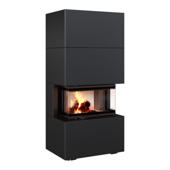
Kratki HOME EASY BOX Installation And Operating Instructions Manual
Hide thumbs
Also See for HOME EASY BOX:
- Installation and operating instructions manual (134 pages) ,
- Installation and operating instructions manual (218 pages)
Advertisement
Available languages
Available languages
Quick Links
Advertisement

Related Manuals for Kratki HOME EASY BOX


Summary of Contents for Kratki HOME EASY BOX
- Page 1 HOME EASY BOX Instrukcja instalacji i obsługi HOME EASY BOX / Installation and operating instructions (EN) HOME EASY BOX / Installations- und Bedienungsanleitung (DE) Producent: www.kratki.com Kratki.pl Marek Bal ul. W. Gombrowicza 4 26-660 Wsola/Jedlińsk...
- Page 2 Wspieramy kampanię Nie Rób Dymu www.nierobdymu.com, fb/nierobdymu DLA INSTALATORA: Zostawić instrukcję razem z urządzeniem. WŁAŚCICIEL (KONSUMENT): Zachowaj niniejszą instrukcję do przyszłego użytku. For the INSTALLER: Leave the manual with the device. CONSUMER: Keep this manual for future reference. Für den INSTALLATEUR: Lassen Sie das Handbuch bei dem Gerät. VERBRAUCHER: Bewahren Sie dieses Handbuch zum späteren Nachschlagen auf.
- Page 3 Przeczytaj instrukcję do końca i udostępnij ją każdemu ewentualnemu użytkownikowi urzą- dzenia zanim podejmie się jego obsługi, montażu lub demontażu. Dziękujemy za zaufanie i wybór naszego urządzenia HOME EASY BOX. To urządzenie zostało zaprojektowane z myślą o Państwa bezpieczeństwie i komforcie. Wyrażamy pewność, że będą...
- Page 4 WYMIARY ZABUDOWY Rys. 1. Rys. 1. Zwymiarowany rysunek zabudowy HOME EASY BOX...
-
Page 5: Ogólne Informacje
UWAGA: UCHYLENIE SIĘ OD ZALECEŃ NINIEJSZEJ INSTRUKCJI W ODNIESIENIU DO INSTA- LACJI, OBSŁUGI LUB UCHYLENIE SIĘ OD ZALECEŃ DOTYCZĄCYCH DOZWOLONYCH CZĘŚCI I AKCESORIÓW DLA TEGO URZĄDZENIA MOŻE SKUTKOWAĆ POWAŻNYMI URAZAMI LUB USZKODZENIEM MIENIA. KAŻDY MODEL ZABUDOWY JEST MODELEM DEDYKOWANYM, TO ZNACZY, ŻE JEST PRZEZNA- CZONY TO INTUICYJNEGO I SZYBKIEGO ZABUDOWANIA TYLKO TEGO MODELU KOMINKA, KTÓRY JEST WYMIENIONY NA STRONIE TYTUŁOWEJ ORAZ W OPISIE INSTALACJI. - Page 6 INFORMACJE DOTYCZĄCE BEZPIECZEŃSTWA Ze względu na możliwość występowania wysokich temperatur, zwłaszcza na szybach urządzenia, wszelkie materiały łatwopalne powinny być zlokalizowane w bezpiecznej odległości od urządze- nia, w tym od elementów jego zabudowy. Dzieci osoby starsze oraz inne osoby powinny zostać poinformowane i ostrzeżone o możliwości występowania wysokich temperatur na urządzeniu w trakcie jego pracy i zaraz po jego wygaszeniu oraz powinny unikać...
-
Page 7: Montaż Urządzenia
ZASADY INSTALACYJNE Instalacja powinna być przeprowadzona zgodnie z wymogami prawa obowiązującego na terenie da- nego kraju lub regionu. W razie braku takich przepisów, należy stosować się do zasad zawartych w tej instrukcji oraz zasad bezpieczeństwa przeciwpożarowego. To urządzenie zostało przebadane pod kątem jakości i bezpieczeństwa oraz było certyfikowane przez notyfikowany instytut badawczy, zaś... - Page 8 Krok 2. Zamontuj elementy konstrukcyjne, szkieletu zabudowy, montowane do podstawy zgodnie ze schematem poniżej. Krok 3. Zamontuj, zgodnie ze schematem poniżej, górną część konstrukcji szkieletu zabudowy.
- Page 9 Krok 4. Po montażu konstrukcji szkieletu zabudowy należy zamontować maskownicę zgodnie ze schematem poniżej skręcając ją na otworach znajdujących się w narożnikach maskownicy. Pozostaw lekki luz na potrzeby montażu dolnych paneli zabudowy. Krok 5. Zamontuj cztery elementy pleców urządzenia wsuwając je lekko od góry we wcięcia w kon- strukcji szkieletu zabudowy.
- Page 10 Krok 6. Przykręć osłonę górną zgodnie ze schematem poniżej. Krok 7. Zamontuj osłony boczne, zaczynając od dołu, zgodnie ze schematem poniżej. Przesłony wy- starczy założyc wsuwając je lekko we wcięcia w szkielecie konstrukcji zabudowy. Po ich montażu, skręć mocno również maskownicę zamontowaną zgodnie z krokiem 4.
- Page 11 Krok 8. Zamontuj osłony boczne na kolejnym poziomie, zgodnie ze schematem poniżej. Przesłony wystarczu założyc wsuwając je lekko we wcięcia w szkielecie konstrukcji zabudowy. Krok 9. Skręć ze sobą pozostałe elementy zabudowy zgodnie ze schematem poniżej, następnie przejdź do kolejnego kroku.
- Page 12 Krok 10. Założ ostatnie elementy zabudowy wsuwając je delikatnie od góry we wcięcia w szkielecie konstrukcji zabudowy. Krok 11. Po montażu zabudowy i urządzenia należy wyłamać przesłonę w zabudowie, w miejscu, w którym będzie wyprowadzony komin aby swobodnie wyprowadzić rurę spalinową. WYBÓR MIEJSCA UMIEJSCOWIENIA URZĄDZENIA W DEDYKOWANEJ ZABUDOWIE.
- Page 13 UWAGA!!! Konserwacji urządzenia może dokonać jedynie wykwalifikowany serwisant. Należy pamiętać również, że każde urządzenie grzewcze wymaga przeglądów kominiarskich zgodnie z wytycz- nymi lokalnego prawa budowlanego, ale nie rzadziej niż raz na rok. • Urządzenie należy poddawać okresowym przeglądom minimum raz w roku. •...
- Page 14 Read the manual to the end and make it available to any possible user of the device before operating, installing or dismantling it. Thank you for your confidence and choice of our HOME EASY BOX. This device was designed with your safety and comfort in mind. We are confident that you will be satisfied with your cho- ice because of the commitment we put into the design and production of this device.
-
Page 15: Installation Dimensions
INSTALLATION DIMENSIONS Fig. 1 Dimensional drawing of the HOME EASY BOX... -
Page 16: Background Information
NOTE: FAILURE TO FOLLOW THE INSTRUCTIONS IN THIS MANUAL WITH RESPECT TO INSTAL- LATION, OPERATION, OR FAILURE TO FOLLOW THE INSTRUCTIONS FOR PERMITTED PARTS AND ACCESSORIES FOR THIS DEVICE MAY RESULT IN SERIOUS INJURY OR DAMAGE TO PRO- PERTY. EACH INSTALLATION MODEL IS A DEDICATED MODEL, THAT IS TO SAY, IT IS INTENDED FOR INTUITIVE AND QUICK INSTALLATION ONLY OF THE FIREPLACE MODEL THAT IS LISTED ON THE TITLE PAGE AND IN THE INSTALLATION DESCRIPTION. -
Page 17: Safety Information
SAFETY INFORMATION Due to the possibility of high temperatures, especially on the device’s panes, all flammable mate- rials should be located at a safe distance from the device, including its built-in elements. Children, elderly people and others should be informed and warned of the possibility of high temperatures on the appliance during and immediately after its operation and should avoid contact with the appliance to prevent burns and ignition of clothing. -
Page 18: Installation Rules
INSTALLATION RULES The installation should be carried out in accordance with the requirements of the law in force in the country or region concerned. In the absence of such regulations, the rules contained in this manual and fire safety rules should be followed. This appliance has been tested for quality and safety and has been certified by a notified testing insti- tute, and the housing has only been tested for strength and safety with this appliance! INSTALLATION OF THE DEVICE... - Page 19 Step 2. Mount the structural elements, the frame, to the base according to the diagram below. Step 3. Mount the top of the frame structure according to the diagram below.
- Page 20 Step 4. After the installation of the frame structure, the grille should be mounted in accordance with the diagram below by turning it on the holes in the corners of the grille. Leave a slight slack for the installation of the bottom panels. Step 5.
- Page 21 Step 6. Screw the top cover as shown below. Step 7. Mount the side covers, starting from the bottom, according to the diagram below. Simply insert the covers by sliding them slightly into the notches in the frame. After installation, also tighten the grille installed according to step 4.
- Page 22 Step 8. Mount the side covers on the next level, as shown in the diagram below. The side covers can be inserted by inserting them slightly into the notches in the frame of the building structure. Step 9. Screw together the other components according to the diagram below, then proceed to the next step.
- Page 23 Step 10. Insert the last building elements by gently sliding them from above into the notches in the frame of the building structure. Step 11. After the installation of the unit and the installation, the cover must be broken out in place, in which the chimney will be led out in order to freely lead the flue pipe.
- Page 24 WARNING!!!! The unit may only be maintained by a qualified service technician. It should also be remembe- red that every heating appliance requires chimney sweeps in accordance with the guidelines of the local building law, but at least once a year. - The device should be periodically inspected at least once a year.
- Page 25 Verfügung, bevor Sie es in Betrieb nehmen, installieren oder demontieren. Vielen Dank für Ihr Vertrauen und die Wahl unserer HOME EASY BOX. Dieses Gerät wurde im Hinblick auf Ihre Sicherheit und Ihren Komfort entwickelt. Wir sind zuversichtlich, dass Sie mit Ihrer Wahl aufgrund des Engagements, das wir in das Design und die Produktion dieses Geräts...
- Page 26 EINBAUMAßE Abb. 1 Maßzeichnung der HOME EASY BOX...
- Page 27 HINWEIS: DIE NICHTBEACHTUNG DER ANWEISUNGEN IN DIESEM HANDBUCH IN BEZUG AUF INSTALLATION, BETRIEB ODER DIE NICHTBEACHTUNG DER ANWEISUNGEN FÜR ZULÄSSIGE TEILE UND ZUBEHÖR FÜR DIESES GERÄT KANN ZU SCHWEREN VERLETZUNGEN ODER SACH- SCHÄDEN FÜHREN. JEDES INSTALLATIONSMODELL IST EIN DEDIZIERTES MODELL, D.H. ES IST NUR FÜR DIE IN- TUITIVE UND SCHNELLE INSTALLATION DES KAMINMODELLS VORGESEHEN, DAS AUF DER TITELSEITE UND IN DER INSTALLATIONSBESCHREIBUNG AUFGEFÜHRT IST.
- Page 28 SICHERHEITSHINWEISE Wegen der Möglichkeit hoher Temperaturen, insbesondere an den Scheiben des Geräts, sollten alle brennbaren Materialien in einem sicheren Abstand zum Gerät, einschließlich seiner eingebau- ten Elemente, angeordnet werden. Kinder, ältere Menschen und andere Personen sollten über die Möglichkeit hoher Temperaturen am Gerät während und unmittelbar nach dem Betrieb informiert und gewarnt werden und den Kontakt mit dem Gerät vermeiden, um Verbrennungen und Entzün- dungen der Kleidung zu vermeiden.
- Page 29 INSTALLATIONSREGELN Die Installation sollte in Übereinstimmung mit den Anforderungen des nationalen oder regionalen Rechts durchgeführt werden. In Ermangelung solcher Vorschriften sollten die in diesem Handbuch enthaltenen Regeln und die Brandschutzregeln befolgt werden. Dieses Gerät wurde auf Qualität und Sicherheit geprüft und von einem notifizierten Prüfinstitut zertifi- ziert, und das Gehäuse wurde nur bei diesem Gerät auf Festigkeit und Sicherheit geprüft! EINRICHTUNG Das Gerät sollte gemäß...
- Page 30 Schritt 2. Montieren Sie die Strukturelemente, den Rahmen, an der Basis gemäß dem untenstehenden Schema. Schritt 3. Montieren Sie die Oberseite der Rahmenstruktur entsprechend der folgenden Abbildung.
- Page 31 Schritt 4. Nach der Installation der Rahmenstruktur sollte das Gitter gemäß dem folgenden Schema montiert werden, indem es auf die Löcher in den Ecken des Gitters gedreht wird. Lassen Sie für die Installation der Bodenplatten ein wenig Spielraum. Schritt 5. Setzen Sie die vier Komponenten der Rückseite des Geräts ein, indem Sie sie leicht von oben in die Kerben der Rahmenstruktur schieben.
- Page 32 Schritt 6. Schrauben Sie die obere Abdeckung wie in der folgenden Abbildung gezeigt. Schritt 7. Montieren Sie die Seitenabdeckungen, von unten beginnend, entsprechend dem untenste- henden Schema. Setzen Sie die Abdeckungen einfach ein, indem Sie sie leicht in die Aussparungen im Rahmen schieben.
- Page 33 Schritt 8. Montieren Sie die Seitenabdeckungen auf der nächsten Ebene, wie in der Abbildung unten gezeigt. Die Seitenabdeckungen können durch leichtes Einfügen in die Aussparungen im Rahmen der Gebäudestruktur eingefügt werden. Schritt 9. Verschrauben Sie die anderen Komponenten gemäß dem folgenden Diagramm und fahren Sie dann mit dem nächsten Schritt fort.
- Page 34 Schritt 10. Setzen Sie die letzten Bauelemente ein, indem Sie sie von oben vorsichtig in die Aussparun- gen im Rahmen der Gebäudestruktur schieben. Krok 11. Nach der Installation des Geräts und der Installation muss die Abdeckung an Ort und Stelle ausgebrochen werden, in dem der Schornstein nach außen geführt wird, um das Rauchrohr frei zu führen.
- Page 35 WARNUNG!!!! Das Gerät darf nur von einem qualifizierten Servicetechniker gewartet werden. Es sollte auch daran erinnert werden, dass für jedes Heizgerät Schornsteinfeger nach den Richtlinien des örtlichen Baugesetzes, jedoch mindestens einmal im Jahr, erforderlich sind. - Das Gerät sollte regelmäßig, mindestens einmal pro Jahr, überprüft werden. - Die Reinigung sollte regelmäßig oder bei Auftreten von überschüssiger Asche erfolgen.
- Page 36 (PL) SPRZEDAJĄCY Nazwa: Pieczęć i podpis sprzedawcy; Adres: Tel/fax: Data sprzedaży: NABYWCA WKŁADU Wkład kominkowy powinien być zainstalowany zgodnie Data i czytelny podpis nabywcy; z obowiązującymi w kraju przepisami i regułami, z postano- wieniami instrukcji obsługi przez instalatora posiadającego stosowne uprawnienia. Oświadczam, iż...
- Page 37 (PL) REJESTR PRZEGLĄDÓW PRZEWODU DYMOWEGO Przegląd przy instalacji wkładu Data, podpis i pieczęć kominiarza Data, podpis i pieczęć kominiarza Data, podpis i pieczęć kominiarza Data, podpis i pieczęć kominiarza Data, podpis i pieczęć kominiarza Data, podpis i pieczęć kominiarza Data, podpis i pieczęć kominiarza Data, podpis i pieczęć...
-
Page 38: Support Services
SELLER Seller’s seal and signature; Name: Address: Tel/fax: Date of sale: INSERT BUYER The fireplace insert should be installed in accordance with Date and legible signature of the Buyer; the rules and regulations valid in the country, the manual provisions by the installer having required qualifications. I hereby declare that having read the operating manual and the guarantee conditions in case of failure to observe the provisions included there the producer bears no liability for... - Page 39 REGISTER OF SMOKE DUCT INSPECTIONS Inspection during the insert installation Date, signature and seal of the chimney sweeper Date, signature and seal of the chimney sweeper Date, signature and seal of the chimney sweeper Date, signature and seal of the chimney sweeper Date, signature and seal of the chimney sweeper Date, signature and seal of the chimney sweeper Date, signature and seal of the chimney sweeper...
- Page 40 Kratki.pl Marek Bal ul. Gombrowicza 4, Wsola, 26-660 Jedlińsk, Poland tel. 00 48 48 389 99 00, 00 48 48 384 44 88, fax 00 48 48 384 44 88 wew. 106 www.kratki.com AP/02/2020...
Need help?
Do you have a question about the HOME EASY BOX and is the answer not in the manual?
Questions and answers