
Related Manuals for Brusa NLG513


Summary of Contents for Brusa NLG513
- Page 1 TECHNICAL DATA AND START-UP NLG513 NLG513 Translation of the original German operating instructions BRUSA Elektronik AG Neudorf 14 CH-9466 Sennwald +41 81 758 19 00 www.brusa.biz info@brusa.biz...
- Page 2 The content of this document may not be passed on to third parties without the written authorisation of the company BRUSA Elektronik AG - not even in extracts. Any technical information, drawings and photos used are copyrighted and failure to respect this constitutes a punishable offence!
- Page 3 ALIDITY This manual is valid only for the following devices: NLG513-U1-01A (water-cooled version) NLG513-U1-02A (air-cooled version) Decoding of the device designation is as follows: Technical data and start-up NLG5 charger...
-
Page 4: Table Of Contents
TABLE OF CONTENTS Foreword ..........................7 List of Abbreviations ......................7 Safety and Warning Instructions..................8 Symbols and their meaning ......................8 Safety instructions and danger levels ..................9 Generally applicable safety measures ..................10 Safety Installations / Power Limitations ..................13 3.4.1 Control Pilot (CP) ...................... - Page 5 6.8.2 Pin Assignment Modular Plug Input (Device-side) ............. 27 6.8.3 Pin Assignment Modular Plug Output (Device-side) ............27 6.8.4 Pin Assignment Control Plug (Device-side) ............... 28 6.8.4.1 Pin 1 GND ............................29 6.8.4.2 Pin 2 AUX ............................29 6.8.4.3 Pin 3 PON ............................30 6.8.4.4 Pin 4 FLT ............................
- Page 6 6.14.7 Power Indicator ......................... 46 Installation / Start-up ......................47 Installing and Connecting the Charger..................47 Configuring the Charger / Assigning Charging Profiles ............. 50 Pre-charging Voltage ........................ 53 Handling and Operation ....................54 HyperTerminal .......................... 54 8.1.1 Retrieving / Monitoring Operating Data from the Charger ..........54 ChargeStar ..........................
-
Page 7: Foreword
Foreword Dear customer! With the BRUSA NLG5 charger you have obtained a very capable and versatile product. As this is a power electronics product with dangerous voltages and currents, specialist knowledge is required for dealing with it as well as operating it! -
Page 8: Safety And Warning Instructions
Safety and Warning Instructions In this chapter you will find safety instructions which apply to this device. These refer to assembly, start-up and running operation in the vehicle. Always read and observe these instructions in order to protect people's safety and lives and to avoid damage to the device! Symbols and their meaning Throughout this manual, several symbols are used. -
Page 9: Safety Instructions And Danger Levels
Safety instructions and danger levels DANGER This instruction warns against serious, irreversible risks of injury and in some cases death! Avoid these dangers by observing these instructions! WARNING This instruction warns against serious, irreversible risks of injury! Avoid these dangers by observing these instructions! CAUTION This instruction warns against serious, irreversible risks of injury! Avoid these dangers by observing these instructions! -
Page 10: Generally Applicable Safety Measures
Generally applicable safety measures The following safety measures have been developed based on the knowledge of the manufacturer. They are not complete, they can be supplemented by local and/or country-specific safety instructions and guidelines for accident prevention! The system integrator and/or distributor of the device must therefore supplement the present general safety instructions by country-specific and local guidelines. - Page 11 You must make sure that the voltage ranges of the device and the HV battery are identical! Only use compatible and high-quality cabling! For this we recommend our specially configured original BRUSA mains and charging cables. INSTRUCTION Damage to the Charger: ...
- Page 12 3.3.4 Safety Instructions for Electrical Systems DANGER High voltage! Danger to life! Under no circumstances should you touch the HV wires or HV connections without ensuring that there is no voltage beforehand! The device may only be connected by a qualified electrician! ...
-
Page 13: Safety Installations / Power Limitations
Safety Installations / Power Limitations 3.4.1 Control Pilot (CP) The control pilot is a safety installation which also increases the reliability of the charging process of an electric vehicle. It is absolutely necessary if the supply-side charging current exceeds 16 A. The CP signal is fed to the charger from the charging station via an additional contact in the mains plug and thereby transmits the maximum permitted current carrying capacity of the mains socket. -
Page 14: General
Scope of the Entire Documentation INFORMATION In order to successfully commission the charger, you need this manual and the software manual, and possibly further software. BRUSA will be happy to provide this so-called (documentation-) “customer package” by download links. Scope of Delivery... -
Page 15: Optional Scope Of Delivery
Optional Scope of Delivery INFORMATION These accessories can be obtained optionally from BRUSA Elektronik AG. MEANING TYPE ILLUSTRATION 1. 23-pole control plug set, includes: MPAA208 1 piece AMPSEAL 770680-1 control plug for wire diameter of 0.5 mm 23 pieces AMPSEAL 770854-1 crimp terminals... -
Page 16: Eu Guidelines
This manual has been produced under application and consideration of the EC guidelines, national laws and harmonised standards (EN) valid at the time of production relevant to the product NLG5 charger . Contact Information of the Manufacturer BRUSA Elektronik AG Neudorf 14 9466 Sennwald... -
Page 17: Use And Limits Of The Product
Use and Limits of the Product Proper Use The BRUSA NLG5 charger has been designed for the following uses. In the case of planned operations in other areas, please contact the company BRUSA Elektronik AG beforehand at the manufacturer address as given in chapter 4.6. -
Page 18: About This Device
About This Device Technical Data NLG5 NLG5 AC INPUT UNIT AIR-COOLED WATER-COOLED Min. input voltage Max. input voltage Min. input frequency Max. input frequency Max. input current Max. input power (at input current = 16 A) 3.680 3.680 Power factor >... - Page 19 BASIC MECHANICAL DATA NLG5 NLG5 UNIT AIR-COOLED WATER-COOLED Weight IP protection IP54 IP65 Height Width Length (without modular plug) without coolant SAFETY AND PROTECTION FUNCTIONS NLG5 NLG5 UNIT AIR-COOLED WATER-COOLED Insulation testing (AC input / DC output) Power inlet over-voltage protection Short-circuit protection Open output protection Internal over-temperature protection...
-
Page 20: Warnings On The Device
Warning signs are installed on the device to warn the operator of possible dangers. Should one of these warning signs be missing or become illegible due to wear and tear, it must be renewed immediately! To get an original label, please contact BRUSA support at the manufacturer address given in chapter Technical data... -
Page 21: Technical Properties
Technical Properties Covers a large battery voltage range (200 - 520 V Scalable charging power of 3.3 kW – 20 kW (through linkage of several NLG5) Isolation between mains and HV battery by integrated HF transformer Compact and lightweight construction ... -
Page 22: Overview Of The Main Structural Components (Water-Cooled Nlg5)
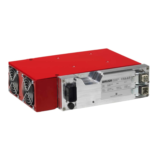
Overview of the Main Structural Components (Water-cooled NLG5) Cooling water inlet (Ø 15,2 mm) Cooling water outlet (Ø 15,2 mm) HV battery socket plug (output) Mains socket plug (input) Type plate Earth connection Pressure equalisation membrane Control plug Technical data and start-up NLG5 charger... -
Page 23: Overview Of The Main Structural Components (Air-Cooled Nlg5)
Overview of the Main Structural Components (Air-cooled NLG5) HV battery socket plug (output) Mains socket plug (input) Type plate Earth connection Control plug Pressure equalisation membrane Fan module 1 Fan module 2 Technical data and start-up NLG5 charger... -
Page 24: Mechanical Connections
Mechanical Connections 6.7.1 Cooling System INSTRUCTION Make sure that no air pockets are available in the cooling system! The vent can also be done by pressure- or vacuum-filling. Please note the maximum allowable system pressure! Air pockets in the cooling system can lead to overheating of the device! Cooling water inlet connection (external Ø... -
Page 25: Electrical Connections
Electrical Connections INFORMATION The electrical connections are the same for all model versions in terms of position and pin assignment. 23-pole control plug Modular plug output See chapter 6.8.4 Pin Assignment Control Plug See chapter 6.8.3 Pin Assignment Modular Plug (Device-side) Output (Device-side) Modular plug input... -
Page 26: Grounding Screw
6.8.1 Grounding Screw WARNING Sparking! Fire hazard! Ensure that the earth connection is connected correctly! A loose ground circuit can lead to sparking and subsequent fires! INFORMATION The grounding screw (1) must be connected with the ground of the vehicle. ... -
Page 27: Pin Assignment Modular Plug Input (Device-Side)
6.8.2 Pin Assignment Modular Plug Input (Device-side) 0 Pin0 (PE) Protective grounding 1 Pin1 (N1) Neutral conductor, power supply input 2 Pin2 Reserve 3 Pin3 (L1) Input mains supply phase 4 Pin4 (CP) Control pilot (CP) 5 Pin5 Reserve 6.8.3 Pin Assignment Modular Plug Output (Device-side) 0 Pin0 (PE) Protective grounding... -
Page 28: Pin Assignment Control Plug (Device-Side)
6.8.4 Pin Assignment Control Plug (Device-side) Earth (minus wiring system, terminal 31) 2. AUX +12 V (plus wiring system, terminal 30) Power on 4. FLT Output 1 (fault, not ready) (switched positive) 6. DO3 Output 2 (programmable) Output 3 (programmable) Output 4 (programmable) 8. -
Page 29: Pin 1 Gnd
6.8.4.1 Pin 1 GND INFORMATION If NLG5 control signals are connected with other vehicle components, then the connection to the vehicle's earth must take place at this pin. Internal wiring Pin 1 GND housing Direct earth connection of the charger's control electronics. 6.8.4.2 Pin 2 AUX INFORMATION... -
Page 30: Pin 3 Pon
6.8.4.3 Pin 3 PON INFORMATION This pin is to be viewed as the main switch input. As soon as the input level is within the range of +5 V…32 V and the power cord is connected, the charging process will be activated in the Automatic mode. -
Page 31: Pin 5 Do2, Pin 6 Do3, Pin 7 Do4
6.8.4.5 Pin 5 DO2, Pin 6 DO3, Pin 7 DO4 INFORMATION These pins can be programmed by the customer and can be used for different purposes (e.g. driving of external LEDs for displaying the state of charge). Internal wiring Pin 5 – 7 DO2, DO3, 200Ω... -
Page 32: Pin 9 Cnl, Pin 10 Cnh
6.8.4.7 Pin 9 CNL, Pin 10 CNH Internal wiring Isolated CAN- Pin 10 Transceiver 2x51uH 2x47p Pin 9 ±33V 20nF The CAN interface has the following features / possibilities: CAN 2.0 B, 500 kHz (default) - parameters can be set (125 / 250 / 500 / 1000 kBit/s). ... -
Page 33: Pin 11 Txd, Pin 12 Rxd
ChargeStar software, charging profiles can be programmed or CAN parameters can be adapted. See chapter 8.2 ChargeStar The firmware for the microprocessor can be downloaded via this interface (provided by BRUSA). Pin 13 PRO must be high for this. -
Page 34: 6.8.4.10 Pin 16 Il1, Pin 17 Il2
6.8.4.10 Pin 16 IL1, Pin 17 IL2 In order to be able to ensure a passive HV - DC-side interlock functionality, two interlock contacts are provided. The interlock circuit does not have to be wired up for the charger to function. In order to ensure safety we recommend that you activate this in all circumstances! Block circuit diagram of the interlock circuit: Technical data... -
Page 35: 6.8.4.11 Pin 18 Di3, Pin 19 Di4
6.8.4.11 Pin 18 DI3, Pin 19 DI4 Internal wiring Pin 18 DI3 Pin 19 DI4 3,3V 1,3V Schmitt Trigger The following functions are carried out via the digital inputs: The charging profile can be governed via these inputs. The transition into the next charging stage can be activated by the input level (high / low or 0 / 1). -
Page 36: 6.8.4.13 Pin 21 Ts2, Pin 22 Ts3
6.8.4.13 Pin 21 TS2, Pin 22 TS3 Internal wiring Pin 21 TS2 Pin 22 TS3 Analog Multi- plexer At the pins 21 TS2 and 22 TS3, the included temperature sensors (NTC with 33 kΩ at 25°C) can be connected. The temperature of the HV battery can be monitored and analysed with these temperature sensors. -
Page 37: Dimensions And Installation Information
Dimensions and Installation Information For the installation of the charger, the following points must be strictly adhered to: Despite the IP protection provided, the charger should be installed in a dry location, protected from splashing water. The air-cooled version must be installed so that a constant fresh air supply is guaranteed. This has a direct influence on the power of the device (derating). -
Page 38: Dimensions (Water-Cooled Nlg5)
6.9.2 Dimensions (Water-cooled NLG5) 6.9.3 Dimensions (Air-cooled NLG 5) Technical data and start-up NLG5 charger... -
Page 39: Basic Principle For Installation Into The Vehicle
6.10 Basic Principle for Installation into the Vehicle Technical data and start-up NLG5 charger... -
Page 40: Block Circuit Diagram Nlg5
6.11 Block Circuit Diagram NLG5 Technical data and start-up NLG5 charger... -
Page 41: Regulation And Control System
6.12 Regulation and Control System The following graph gives an overview of the way the different derating and shut-down installations of the charger work and how they are related. Green = Signal Yellow = Configuration Orange = Power reduction ... -
Page 42: Modes Of Operation
6.13 Modes of Operation 6.13.1 Mode A (Automatic) In this mode, the charger charges the battery in conformity with a programmed charging profile. A charging profile consists in turn of several charging stages in which each charging follows its own I / U profile. The I / U profile in stage 1 is determined using the current level I and the voltage level U . -
Page 43: Mode C (Can Controlled)
The transition into stage 2 can take place as early as phase I or U due to one or more conditions. In stage 2 the voltage level U is usually larger and the current level I is usually smaller than in stage 1. This stage is referred to as Equalisation Charge. -
Page 44: Power Limitations
6.14 Power Limitations In order to permanently protect the NLG5 from overload damages, the charging power is automatically limited through different power limitations. Here checks are constantly made to see whether all operational values are within the permitted range. The charging power is thereby permanently reduced to the level which is permitted under consideration of the current power limitations. -
Page 45: Max. Mains Power
6.14.2 Max. Mains Power The charger constantly monitors the applied charging power and limits this to 3680 W. In a 230 V mains supply, this corresponds to a primary current of 16 A. During this, the maximum permitted mains connection current is ignored and the power limiters Power Indicator and Control Pilot are not considered. -
Page 46: Power Indicator
6.14.7 Power Indicator To limit the mains current manually, a potentiometer or a resistor can be connected between pins 23 and 8 of the control plug. The dependence of the maximum mains current In on the resistor R is as follows: if R >... -
Page 47: Installation / Start-Up
Visually check the packing material and the charger itself in particular for damages before installation. Each charger undergoes a strict quality and function test at BRUSA before distribution. However, we have no control over transportation routes which can sometimes take a long time and the shipping of our products. - Page 48 Close the locking clip (2). INSTRUCTION Pay attention to the cable colours when connecting the battery cable to the HV battery! Battery + = brown (when using the BRUSA KB51A battery cable) Battery = blue (when using the BRUSA KB51A battery cable) Incorrect polarity can lead to damages to the charger! 11.
- Page 49 PROCEDURE STEP ILLUSTRATION / OTHER INFORMATION 12. Connect the mains cable (modular plug input) (1) with the charger. Close the locking clip (2). 13. Connect the charging cable to the charging socket of the vehicle. Technical data and start-up NLG5 charger...
-
Page 50: Configuring The Charger / Assigning Charging Profiles
Configuring the Charger / Assigning Charging Profiles INFORMATION The provided ChargeStar software functions using the following operating systems with 32 processors: Win2000 Win XP Win Vista PROCEDURE STEP ILLUSTRATION / OTHER INFORMATION 1. Ensure that all mechanical and electrical connections are connected with the charger. - Page 51 PROCEDURE STEP ILLUSTRATION / OTHER INFORMATION 9. In the Connection menu, press Connect with NLG (1). The connection to the charger is being established. When the connection is active, the report Connected with device will appear field (2). Check the cable connections in case the connection cannot be established and repeat the procedure.
- Page 52 PROCEDURE STEP ILLUSTRATION / OTHER INFORMATION 14. Disconnect the cable connection between the PC and the charger. INFORMATION The charger is now configured and can be completely installed. For this perform the procedure steps in chapter 7.1 Installing and Connecting the Charger. For further information on the adjustment parameters or the programming of charging profiles, read the following chapters.
-
Page 53: Pre-Charging Voltage
Pre-charging Voltage INFORMATION The following operating principle applies to the BRUSA battery type EVB1: To avoid sparks when switching on, the connected loads are pre-charged with a 50 ohm PTC. For this process, three independent voltage measurements are used. -
Page 54: Handling And Operation
Handling and Operation HyperTerminal 8.1.1 Retrieving / Monitoring Operating Data from the Charger INFORMATION To retrieve the operational data of the charger, you will need a terminal or a terminal programme. In the terminal, data which is transmitted from the charger via the serial interface (RS232) can be represented in text form. - Page 55 PROCEDURE STEP ILLUSTRATION / OTHER INFORMATION 4. Set the connection COM1 in the field (1). Then press the Configure button (2). The dialogue box COM1 Properties is opened. 5. Set the limits as follows: (1) 19200 (2) 8 (3) None (4) 1 (5) Xon / Xoff Close the dialogue box by clicking the OK button (6).
- Page 56 PROCEDURE STEP ILLUSTRATION / OTHER INFORMATION 10. Now in the text field, the operational values of the NLG5 are displayed (Main Characteristics menu). INFORMATION To retrieve current error and warning messages, press the E button on your keypad (Errors & Warnings menu).
-
Page 57: Chargestar
Loading Charging Profiles from the Database INFORMATION With the ChargeStar software, charging profiles configured by BRUSA are supplied which can be used as examples. These can be changed at any time. There is also the possibility of creating your own charging profiles. You can find details on this in chapter 8.2.2 Programming New Charging... - Page 58 PROCEDURE STEP ILLUSTRATION / OTHER INFORMATION 4. To transfer the charging profile to the charger, press Send to NLG in the Profiles menu. The charging profile is transferred to the NLG. INFORMATION The charger must be restarted to adopt / activate the charging profile. After the reset, the charging profile is automatically active.
-
Page 59: Programming New Charging Profiles
The programming of a charging profile should only be carried out by experienced specialist personnel! Incorrectly defined parameters will lead to the malfunctioning of the charger and the connected HV battery! So in case of any questions or confusion, contact BRUSA Support at the manufacturer address given in chapter... - Page 60 PROCEDURE STEP ILLUSTRATION / OTHER INFORMATION 4. Enter the required values in the field (1). See chapter 8.2.7.2 Shut-Down Parameters 5. Configure your charging profile in the field (1). See chapter 8.2.7.3 Parameters for Charging Profiles 6. To save the charging profile, press Save file (1) in the Profiles menu.
- Page 61 PROCEDURE STEP ILLUSTRATION / OTHER INFORMATION 7. To transfer the charging profile to the charger, press Send to NLG in the Profiles menu. The charging profile is transferred to the NLG. INFORMATION The charger must be restarted to adopt / activate the charging profile. After the reset, the charging profile is automatically active.
-
Page 62: Retrieving Current Charging Profile From The Charger
8.2.3 Retrieving Current Charging Profile from the Charger INFORMATION In order to determine which charging profile is currently installed on the charger, this can be called up at any time via ChargeStar. PROCEDURE STEP ILLUSTRATION / OTHER INFORMATION 1. If you have not yet done so, start the ChargeStar software. -
Page 63: Retrieving The Battery Properties Of The Charging Profile
8.2.4 Retrieving the Battery Properties of the Charging Profile INFORMATION Battery properties can be applied while programming a new charging profile and can be saved with the charging profile. Here, the battery types which can or may be charged with this charging profile can be precisely defined. -
Page 64: Retrieving Device Information From The Charger
8.2.5 Retrieving Device Information from the Charger PROCEDURE STEP ILLUSTRATION / OTHER INFORMATION 1. If you have not yet done so, start the ChargeStar software. 2. In the Connection menu, press Connect with NLG (1). The connection to the charger is being established. -
Page 65: Changing The Can Parameters (Options)
8.2.6 Changing the CAN Parameters (Options) INFORMATION In the dialogue box Options, the CAN parameters can be changed. The CAN parameters are set using the existing CAN matrix and should therefore only be changed by experienced specialist personnel! PROCEDURE STEP ILLUSTRATION / OTHER INFORMATION 1. - Page 66 PROCEDURE STEP ILLUSTRATION / OTHER INFORMATION 4. In the dialogue box Options, the different CAN parameters can now be changed. Press the OK button (1) to close the dialogue box. You can find details on the CAN matrix in the Software manual.
-
Page 67: Charging Profile Parameters
8.2.7 Charging Profile Parameters 8.2.7.1 General Parameters WARNING Overheating! Fire hazard! There is a danger of the battery catching fire if the wrong parameters or limit values are entered! Any adjustment values must be adopted from the connected battery's technical documentation or be given clearance by the manufacturer! Nominal voltage of the battery (V): Temperature coefficient of the gassing... -
Page 68: Shut-Down Parameters
8.2.7.2 Shut-Down Parameters WARNING Overheating! Fire hazard! There is a danger of the battery catching fire if the wrong parameters or limit values are entered! Any adjustment values must be adopted from the connected battery's technical documentation or be given clearance by the manufacturer! INFORMATION Shut-down parameters function as an additional safety installation. -
Page 69: Parameters For Charging Profiles
8.2.7.3 Parameters for Charging Profiles A charging profile can be divided into up to 7 stages. Each stage is sub-divided into an I phase and a U phase in which the maximum charging current / maximum charging voltage must be determined. For each stage, one or more parameters can be set which must be reached in order for the transition into the following stage to take place. -
Page 70: Warranty And Guarantee
Warranty and Guarantee The warranty corresponds to the regulations in our currently valid general terms and conditions see under www.brusa.biz/en/support/terms-conditions.html. Instructions regarding disposal A basic requirement for the re-use and recycling of used electronic devices is the correct disposal. With the implementation of the electric and electronic device regulation (ElektroG), since 24 March 2006, electronic devices may no longer be disposed of along with ordinary household waste but must be separately collected and recorded by a specialist services. -
Page 71: Index
Index Block Diagram High voltage Installation into the Vehicle ..........40 The 5 Safety Rules ..............12 Whole ................... 41 Main Contactor Charger Function ................54 Programming ................ 34 ChargeStar Entering Parameters ............. 68 NLG5 Control Pilot ..............13, 22, 45 Product-Lifespan Guidelines ..........
Need help?
Do you have a question about the NLG513 and is the answer not in the manual?
Questions and answers
Hi, my smiths edison transit tipper EV has two brusa chargers if I try charging with 16 or 32 amps of the five led lights the first yellow and red are on both units and fails to start ,initially for 30 seconds on turning mains power on first yellow lights up on both then fans start then clicking noise from passenger side battery box turns fans of and yellow red lights come on?
The issue could be that the Brusa NLG513 charger is cycling on and off because the battery voltage quickly reaches a set threshold (e.g., 393.7V), causing the charger to stop. When the voltage drops below the threshold, it restarts, repeating the cycle. This behavior may prevent stable charging at higher currents like 16 or 32 amps. Additionally, although the charger can output up to 15 amps, losses through the system reduce actual current to about 7–8 amps at the battery, limiting effective charging.
This answer is automatically generated
@Mr. Anderson
Hi again the bottom LEDs green and red flash then both sets of LEDs turn off and the to two on each charger settle at yellow and red , the dash lights when on start are flashing amber the left three and and amber on the right side suggesting I believe only ten percent charge in batterys