Table of Contents
Advertisement
OPERATION MANUAL
INDUCTIVE CHARGING SYSTEM ICS115
- INDUCTIVE CHARGING SYSTEM ICS115 -
FOR INSTALLATION – OPERATION – MAINTENANCE
Translation of original operation manual (English)
Read carefully before use! Keep safe for later reference!
BRUSA Elektronik AG
Neudorf 14
CH–9466 Sennwald
www.brusa.biz
+41 81 758 19 00
Advertisement
Table of Contents

Related Manuals for Brusa ICS115


Summary of Contents for Brusa ICS115
-
Page 1: Dimensions Cpm [Mm]
OPERATION MANUAL INDUCTIVE CHARGING SYSTEM ICS115 - INDUCTIVE CHARGING SYSTEM ICS115 - FOR INSTALLATION – OPERATION – MAINTENANCE Translation of original operation manual (English) Read carefully before use! Keep safe for later reference! BRUSA Elektronik AG Neudorf 14 CH–9466 Sennwald www.brusa.biz... - Page 2 The copyright of this document lies with BRUSA Elektronik AG. The content of this document must not be passed on to third parties – even in extracts – without the written authorization of BRUSA Elektronik AG. All technical specifications, drawings and photos used are protected by copyright.
-
Page 3: Table Of Contents
Electromagnetic Compatibility ....................15 Safety and Warning Signs ......................16 Symbols and their Meaning ...................... 16 Safety Instructions and Danger Levels ..................17 Generally Applicable Safety Instructions .................. 19 5.3.1 Safety Instructions for Thermal Hazards ................19 Operation Manual Inductive Charging System ICS115... - Page 4 8.1.1 Cleanliness of the CPM ..................... 37 8.1.2 Cleanliness of the GPM ..................... 37 Behavior after a vehicle accident ....................38 Deinstallation ..........................38 Disposal ............................38 10.1 Notes for Customer Service ....................38 Operation Manual Inductive Charging System ICS115...
- Page 5 Planning the Assembly and Installation of the ICS ............52 Planning the assembly and installation of the CPM, see Annex 12.7.4..........52 12.5.8 Transport and Storage ....................52 12.6 Deinstallation of the GPM ..................... 54 Operation Manual Inductive Charging System ICS115...
- Page 6 Annex A2 ............................ 64 13.1 Standards and Legal Requirements ..................64 13.2 DECLARATIONS OF CONFORMITY ................... 65 13.2.1 SIMPLIFIED EU-DECLARATION OF CONFORMITY ICS115 ........65 13.2.2 SIMPLIFIED EU-DECLARATION OF CONFORMITY ICS1-WLAN-ATWILC-MU-D ..65 Index ............................66 Glossary ............................. 68 Operation Manual...
-
Page 7: List Of Abbreviations
Time t in second s I [A] Electrical Current Intensity I in Ampere A T [°C] Temperature T in degrees Celsius °C U [V] Inductive Charging System (CPM+GPM) Electrical voltage U in Volt V Operation Manual Inductive Charging System ICS115... -
Page 8: Foreword
Foreword Valued Customer! With the BRUSA Inductive Charging System Model ICS115 you have purchased an inductive charging system with the latest technology. Model ICS115 is an inductive charging system of the 1 Generation for vehicles with high- voltage battery, which is subsequently abbreviated to ICS. Since it concerns high-performance electronics devices, we expect particular caution when dealing with it as well as when handling it! Read through this manual carefully –... -
Page 9: Identification Of The Product Ics
ICS1 WITH THE FOLLOWING DEVICE DESIGNATIONS ICSP11W-U0-01X-Xxx (GPM) ICSS115-U0-01X-Xxx (CPM, 2-HV-Connectors) Explanation of the code for the product identification The breakdown of the device designation for the complete system, the GPM and the CPM, is as follows: GPM: Operation Manual Inductive Charging System ICS115... -
Page 10: Service- And Contact Data
CPM: Service- and Contact Data TYPE OF INQUIRY COUNTRIES CONTACT DATA BMW Customer Support Delivery D, A, CH D–80788 Munich Help and Support Deinstallation and Disposal Germany Tel: +49 89 1250-16000 kundenbetreuung@bmw.de Operation Manual Inductive Charging System ICS115... -
Page 11: Scope Of Supply
Scope of Supply The following items are included in the scope of supply of the ICS system DESCRIPTION QUANTITY ILLUSTRATION Ground Pad Module (GPM) Car Pad Module (CPM) Original Operation Manual Operation Manual Inductive Charging System ICS115... -
Page 12: Product Description Of The Ics
Risk of injury from electromagnetic field! With inductive charging an electromagnetic field is generated under the vehicle. Cardiac pacemakers and medical implants can be affected. Do not reach underneath the vehicle or perform maintenance work during the charging process. Operation Manual Inductive Charging System ICS115... -
Page 13: Proper Intended Use
The product must not be used outside these limits within the respective life phases. Modification of products. It is not permitted to undertake modifications to the product and then continue to use the product. Operation Manual Inductive Charging System ICS115... -
Page 14: Delimitation
4.1.6 Delimitation This operation manual describes the safe handling with the Inductive Charging System in all phases of life. BRUSA Elektronik AG accepts no liability for the incomplete passing on of information from this document, in particular to those persons from the target group defined in chapter 4.1.1... -
Page 15: Energy Efficiency
ICS. Nevertheless, a disturbance of Comfort Access Systems of adjacent vehicles cannot be excluded, since both systems are based on the use of WLAN. Operation Manual Inductive Charging System ICS115... -
Page 16: Safety And Warning Signs
Warning of potentially explosive Warning of dangers from batteries environment Warning of hot surface Warning of high electric voltage Warning of non-ionizing radiation Warning of the risk of fire Warning of magnetic field Warning of hot surfaces Operation Manual Inductive Charging System ICS115... -
Page 17: Safety Instructions And Danger Levels
This sign warns of a minor risk of injury! Avoid this danger by observing this notice! NOTICE This notice warns of possible material damage, if the following instructions and work sequences are not observed. Operation Manual Inductive Charging System ICS115... - Page 18 INFORMATION This type of notice is used to communicate important information for the reader. Operation Manual Inductive Charging System ICS115...
-
Page 19: Generally Applicable Safety Instructions
Risk of fire! Mains connection cables must not be operated coiled up. In the coiled up state the cable can ignite due to a build-up of heat! Therefore basically uncoil the mains connection cable completely! Operation Manual Inductive Charging System ICS115... -
Page 20: Safety Instructions For Handling And Operation
No person must connect a GPM to the power supply without knowing the safety- and warning signs. A GPM may only be connected to the power supply, when all persons who are working near the GPM are aware of the potential dangers. Operation Manual Inductive Charging System ICS115... - Page 21 Make sure, that the voltage ranges of the device and the HV-battery are identical! Use only technically suitable and high-quality cabling! In case of uncertainties, please contact BRUSA Elektronik AG beforehand at the manufacturer address specified in chapter 3.3. NOTICE Damage to the devices: ...
-
Page 22: Safety Equipment / Power Limitations
(see manufacturer address in chapter )! Contact customer service. 5.4.3 Overcurrent Protection NOTICE It is prescribed to insert suitable overcurrent protection between CPM and HV-battery of the vehicle! Operation Manual Inductive Charging System ICS115... -
Page 23: Thermal Overload Protection (Derating)
The wiring of the Interlock-Pins is not functionally relevant for the CPM, however to guarantee the safety we definitely recommend using an interlock system! 5.4.6 Living Object Detection (LOD) DANGER Operation Manual Inductive Charging System ICS115... -
Page 24: Foreign Object Detection (Fod)
As a result it is ensured, that no energy is transmitted to the system environment. This safety function also prevents the heating of electrically conductive foreign objects during the charging process and thus reduces thermal dangers, such as e.g. fire or hot surfaces. Operation Manual Inductive Charging System ICS115... -
Page 25: Enabling The Positioning
Communication failure between CPM and vehicle-CAN (Vehicle-CAN, VCAN) With a change of position of the CPM until the device is no longer physically able to transmit energy Malfunction in the device Operation Manual Inductive Charging System ICS115... -
Page 26: Warnings
If one of these warning signs is missing or no longer legible due to wear, it must be renewed immediately! To obtain an original label, please contact your customer service! Figure 1: Warning notice (colored) on GPM underside (left) and CPM (right) Operation Manual Inductive Charging System ICS115... -
Page 27: Commissioning And Use Of The Ics
Ensure for sufficient lighting during installation, operation and deinstallation. INFORMATION Visually inspect the packaging material and in particular the GPM itself for damage before installation. Every GPM undergoes a strict quality- and function control before delivery. However we Operation Manual Inductive Charging System ICS115... - Page 28 Use resources such as floor-mounted Ensure safe and secure laying of the cable from the power ducting or similar to avoid tripping connection to the GPM. Avoid posing a tripping hazard due to hazards. protruding cable. Operation Manual Inductive Charging System ICS115...
- Page 29 7.3.1.4, insofar as the vehicle is still sensed in the transmit range of the GPM, or the GPM switches to the status NOT CONNECTED, if the vehicle should not have any WLAN reception from the GPM, see 7.3.1.3 Operation Manual Inductive Charging System ICS115...
-
Page 30: Control And Operation
Take into consideration the properties and parameters of the CPM and GPM, if you have modifications carried out on the vehicle or perform them yourself! Please note, that material damage to the vehicle or ICS is possible, if modifications to the vehicle (tuning, lowering the vehicle) are undertaken. Operation Manual Inductive Charging System ICS115... -
Page 31: Displays And Signals
/Living Object Detection, charging the vehicle is not possible, because the GPM can no longer safely evaluate, whether an object is present or not. If the GPM requires an initialization of the foreign-/living object detection, you recognize this by this flashing pattern: Operation Manual Inductive Charging System ICS115... - Page 32 If a suitable vehicle (with CPM) is configured for charging with the GPM and if this vehicle is near the GPM, then a WLAN connection is established between CPM and GPM. The charging process is controlled automatically from the vehicle via this WLAN connection. Figure 6: Flashing pattern in status Connected Operation Manual Inductive Charging System ICS115...
- Page 33 In this case check the GPM and make sure, that the GPM is free of foreign objects of any kind. 0,25s 0,25s 0,25s Figure 9: Flashing pattern in status Foreign Object Detected Operation Manual Inductive Charging System ICS115...
-
Page 34: Gpm Cooling System Fan
1. Keep calm! extremities 2. Remove yourself immediately from the charging environment! 3. Visit a doctor. Feeling unwell 1. Keep calm! 2. Remove yourself immediately from the environment of the charging station! 3. Visit a doctor. Operation Manual Inductive Charging System ICS115... -
Page 35: Troubleshooting By The User
GPM is installed. 5. If the error still occurs, contact customer service. Operation Manual Inductive Charging System ICS115... -
Page 36: Maintenance
In addition, jewelry (rings, wristwatches, etc.) can heat up considerably and become damaged or lead to burns. People with a cardiac pacemaker or implanted defibrillator should keep away from the vicinity of the system during the charging process. Keep animals away from the system during operation. Operation Manual Inductive Charging System ICS115... -
Page 37: Cleanliness
Deviation from recommended measures for cleaning can result in damage to the GPM. During use the GPM must be kept clean. It is recommended to keep the GPM clean by means of the following measures: Operation Manual Inductive Charging System ICS115... -
Page 38: Behavior After A Vehicle Accident
The disposal by a specialist company contributes significantly towards avoiding dangers for people and nature. In the case of disposal we therefore recommend that you contact a recognized specialist waste management company. Operation Manual Inductive Charging System ICS115... -
Page 39: Legal Notices
For damage that occurs during proper intended use and despite observance of the safety instructions in this document, BRUSA provides a warranty for the ICS. The warranty is in accordance with the provisions in our currently valid General Terms and Conditions, which can be viewed at www.brusa.biz/support/agb.html. -
Page 40: Annex A1
Magnetic flux density of the GPM at vehicle limitation 4.6*10 WLAN-Signal Frequency Max. transmit power Positioning signal Frequency s Max. radiated magnetic field strength at 125 kHz 17.5 dBµA/m 12.1.2 Dimensions and Center of Gravity 12.1.2.1 Dimensions GPM [mm] Operation Manual Inductive Charging System ICS115... - Page 41 12.1.2.2 Center of Gravity GPM [mm] Intake duct 12.1.3 Dimensions CPM [mm] Service flap with mains cable connection Operation Manual Figure 11: Center of gravity of GPM with fan intake duct Inductive Charging System ICS115...
-
Page 42: Center Of Gravity Cpm [Mm]
12.1.4 Center of Gravity CPM [mm] Operation Manual Inductive Charging System ICS115... -
Page 43: Technical Data
9 – 16 LV-wiring system max. voltage CPM (device destruction) IP protection class IP6K9K, IP65 Insulation class acc. EN 61140 Protection class I BASIC MECHANICAL DATA UNIT Height above ground GPM Height above ground CPM Operation Manual Inductive Charging System ICS115... -
Page 44: Conditions For Storage And Transport Of The Ics
A or class B in the electric circuit of the connection for the GPM, which monitors exclusively the function of the GPM. In addition a functional electrical safety device must be installed in the electric circuit of the power supply for the GPM. Operation Manual Inductive Charging System ICS115... -
Page 45: Mechanical Data Of The Cpm
12.4.1 Protective Equipment during Transport and Storage For the installation the following protective equipment must be worn, to prevent possible injuries in the respective work steps: Transport / Removal / Storage: Protective gloves against mechanical risks and safety shoes Operation Manual Inductive Charging System ICS115... -
Page 46: Protective Equipment During Installation
GPM in the charging station the dimensions of the vehicle must be taken into consideration. For damage that is due to faulty installation of the GPM in the charging station, no liability is accepted on the part of the manufacturer. Operation Manual Inductive Charging System ICS115... - Page 47 Mark on the floor the position and middle of the front license plate holder. c. Mark on the floor the position of the outer edges of the front wheels. Figure 13 Example for positioning the GPM with desired forward parking Operation Manual Inductive Charging System ICS115...
-
Page 48: Optional Installation Of The Gpm With Mounting Rails
Figure 15: Bottom of the GPM with mounting rails (blue). The right-hand rail snaps into recesses of the GPM-housing. The left-hand rail (on the cable bushing) is screwed tight at the side of the service cover. Operation Manual Inductive Charging System ICS115... - Page 49 Figure 16: View of GPM with mounting rails. Figure 17: Drilling template for GPM mounting rail Proceed as follows: Operation Manual Inductive Charging System ICS115...
-
Page 50: Line Connections Cpm
75°C (167°F). The color assignment must be observed without fail, see Table 2: Assignment Mains Connection Cable GPM. Color brown Phase L1 blue Neutral conductor yellow/green Protective conductor Table 2: Assignment Mains Connection Cable GPM Operation Manual Inductive Charging System ICS115... - Page 51 Figure 18: Service flap with LED - View Figure 19: Connection of a cable to the cage clamp in the service flap Operation Manual Inductive Charging System ICS115...
-
Page 52: Planning The Assembly And Installation Of The Ics
Note the technical specifications of the ICS, e.g. weight and center of gravity! Please note, that with careless handling of the CPM, injuries are possible: injuries on ICS or packaging, as well as injuries through allowing the ICS to fall (in packaging)! Operation Manual Inductive Charging System ICS115... - Page 53 GPM during the manipulation. a change of the relative position of the center of gravity of the GPM, due to contact with smooth surfaces or due to the GPM shifting in the packaging. Operation Manual Inductive Charging System ICS115...
-
Page 54: Deinstallation Of The Gpm
GPM is switched off. Disconnect the GPM from the connection to the power supply. Take into consideration the instructions for transport and Stow the GPM safely for removal. storage in chapter 12.5.8 Operation Manual Inductive Charging System ICS115... -
Page 55: Vehicle Integration Of The Cpm
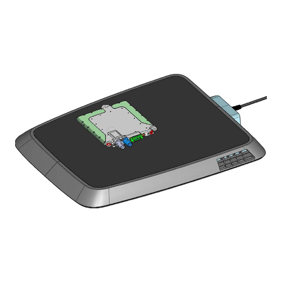
The mechanical fastening must be positioned, so that the device is installed firmly and with as little vibration as possible. Cable feeds must not bunch up on sharp-edged components. The CPM is to be installed at the three fastening points illustrated: Operation Manual Inductive Charging System ICS115... -
Page 56: Line Connections Cpm
12.7.3 Line Connections CPM Operation Manual Inductive Charging System ICS115... - Page 57 We generally recommend to route the ground lines of all drive components together at one ground point. This minimizes the risk of potential differences, which can lead to malfunctions of individual drive components! The cable cross-section of the ground line must correspond with the dimension of the HV-lines. Operation Manual Inductive Charging System ICS115...
- Page 58 Kl30C HVIL_out Kl30 Crash HV-Interlock loop output Not contacted Not contacted Kl31 Ground (supply system Minus) EV_CAN_L EV CAN low HVIL_in HV-Interlock loop input Not contacted Debug_CAN_H Debug CAN high Debug_CAN_L Debug CAN low Operation Manual Inductive Charging System ICS115...
- Page 59 HV-Interlock Loop Input HVIL_out HV-Interlock Loop Output Housing (equipotential bonding) 12.7.3.4 Pin Assignment HV-Connector (Code B) HV_DC_+ HV Battery Plus HV_DC_- HV Battery Minus HVIL_in HV-Interlock Loop Input HVIL_out HV-Interlock Loop Output Housing (equipotential bonding) Operation Manual Inductive Charging System ICS115...
-
Page 60: Planning The Assembly And Installation Of The Cpm
Note the technical specifications of the CPM, e.g. weight. Please note, that with careless handling of the CPM, injuries are possible: injuries on CPM or packaging, as well as injuries through allowing the CPM to fall! Operation Manual Inductive Charging System ICS115... -
Page 61: Installation Of The Cpm
Visually inspect the packaging material and in particular the CPM itself for damage before installation. At BRUSA every CPM undergoes a strict quality- and function control before delivery. However we have no influence on the long transport routes in some cases and the loading activities of our products. -
Page 62: Deinstallation Of The Cpm
After the 8 work step the CPM is installed ready. 12.7.7 Deinstallation of the CPM The deinstallation of the CPM component may only be performed by specialist personnel. Contact customer service. Operation Manual Inductive Charging System ICS115... - Page 63 Interrupt the CPM Interlock. Follow the instructions for the removal of the CPM for the intended vehicle of the respective vehicle manufacturer. Dispose CPM, taking into consideration regulations disposal of electrical devices in chapter 10.1. Operation Manual Inductive Charging System ICS115...
-
Page 64: Annex A2
Limitation of human exposure to electromagnetic fields from devices 13 EN 62479:2010 Assessment of the compliance of low power electronic and electrical equipment with the basic restrictions related to human exposure to electromagnetic fields (10 MHz to 300 GHz) Operation Manual Inductive Charging System ICS115... -
Page 65: Declarations Of Conformity
13.2 DECLARATIONS OF CONFORMITY 13.2.1 SIMPLIFIED EU-DECLARATION OF CONFORMITY ICS115 BRUSA Elektronik AG herewith declares, that the radio equipment type ICS115 conforms to the directive 2014/53/EU. The complete text of the EU-Declaration of Conformity is available at the following Internet address: www.brusa.biz/<todo... -
Page 66: Index
CPM, 10 CPM, 38 GPM, 9 GPM, 37 ICS, 9 Disposal, 36 Removal of the ICS, 36 Efficiency, 14 Scope of Application Emergency situations, 32 ICS, 12 Energy Efficiency, 14 Scope of supply, 11 Operation Manual Inductive Charging System ICS115... - Page 67 Storage ICS, 40 CPM, 55 Transport GPM, 49 CPM, 55 Support, 10 GPM, 49 Technical Data Troubleshooting CPM, 41 by User, 33 Energy Supply, 14 Warranty, 36 GPM, 41 Operation Manual Inductive Charging System ICS115...
-
Page 68: Glossary
Physical effect, during which electrically conductive objects situated within the field heat up and therefore can cause dangers for people (e.g. burning, fire). Electromagnetic Induction Physical effect, on which the cordless transmission of energy from the charging station (GPM) to the vehicle (CPM) is based Operation Manual Inductive Charging System ICS115...
Need help?
Do you have a question about the ICS115 and is the answer not in the manual?
Questions and answers