Table of Contents
Advertisement
Quick Links
Advertisement
Table of Contents

Subscribe to Our Youtube Channel
Related Manuals for NDT Systems NovaScope 5000


Summary of Contents for NDT Systems NovaScope 5000
-
Page 2: Table Of Contents
www.ndtsystems.com TABLE OF CONTENTS Section Page SAFETY SUMMARY ..............WARRANTY . - Page 3 5.20 GATE DISPLAY SWITCH ............5.21 GATE DISPLAY "T"...
- Page 4 6.4 SUPPLEMENTAL FUNCTION ........... . 6.4.1 Special TAC-GATE .
-
Page 5: Safety Summary
SAFETY SUMMARY This summarized safety summary is intended for both operating and service personnel. WARNING TERMS OF INSTRUMENT Caution means a personal injury hazard that is not immediately accessible as the markings are read, or a property/instrument hazard. DANGER means a personal injury hazard that is immediately accessible as the marking is read. -
Page 6: Warranty
The final determination of the existence of a defect or breach of this warranty shall be made by NDT Systems, Inc. This warranty shall extend to the buyer only, and shall not be assignable or transferable to any other person. -
Page 7: Specifications
1. SPECIFICATIONS DIGITAL DISPLAY Four Digit “Virtual” (LED), With 0.05 Second Update DIMENSIONAL READOUT English And Metric (Selector Switch) GAGING RANGE English: 0.005-10"; Metric: 0.13mm To 100mm (Depending Upon Material) DIGITAL RESOLUTION English Metric ±0.0001" On 1" Range ±0.001mm On 10mm Range ±0.001"... -
Page 8: Introduction
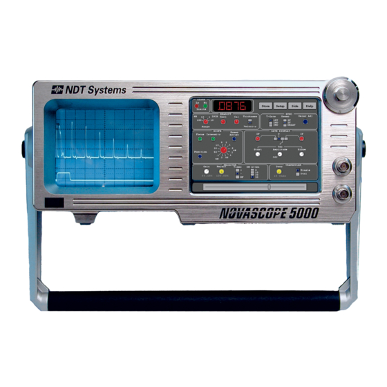
2. INTRODUCTION The NovaScope 5000 is the most significant improvement in the NovaScope series of precision ultrasonic thickness gages and represents the most versatile and precise digital ultrasonic thickness gage available on the market today. By means of its dual-trace CRT based scope display and variety of “virtual”... -
Page 9: General Applications
NovaScope. The data processed by the NovaScope can be presented as a familiar C-scan or fed (via rear panel digital or analog outputs) to a computer, recorder/logger or NDT Systems portable ultrasonic imaging system, PortaScan. -
Page 10: General Operating Principles
4. GENERAL OPERATING PRINCIPLES This section presents an elementary overview of the ultrasonic principles and general instrumentation concepts for the NovaScope. Detailed discussions on the specific controls/features and operational/calibration procedures for the NovaScope are presented in subsequent sections. The small amount of time spent in review of this section will lead to a more thorough understanding if thickness gaging in general. -
Page 11: Thickness Gaging Concept
TABLE I Characteristic Ultrasonic Velocities for Some Selected Common Materials (At Room Temperature, Unless Otherwise Noted) MATERIAL VELOCITY - in/us VELOCITY - mm/us ACRYLIC RESIN 0.105 2.67 AIR (20EC) 0.014 0.34 ALUMINUM 0.249 6.32 BRASS, NAVAL 0.174 4.43 BRONZE,PHOSPHO 0.139 3.53 0.181 4.60... -
Page 12: Instrumentation Concepts
where pulse-echo round trip across material sectional thickness material sectional thickness characteristic ultrasonic velocity for material compensation factor for the fact that the round trip time represents twice the time for the ultrasonic energy to travel across the material thickness. This relationship shows that, for a given material (of constant ultrasonic velocity), the pulse-echo time period will double if the thickness doubles. - Page 13 which converts electrical energy into mechanical energy and vice-versa. The piezoelectric material in the transducer is shaped into a thin wafer whose thickness is resonant at the ultrasonic frequency range desired. An ultrasonic (mechanical) damping agent is bonded to the back surface of the wafer so that the transducer pulse duration (pulse width) is very short.
-
Page 14: A-Scan Presentation
The horizontal axis across which no signal occurs (zero amplitude) c a l l e d t h e b a s e l i n e . s u c h time-amplitude display readily depicts the vibrational nature of the ultrasonic pulse as a burst of damped oscillations (damped sinusoid) at a given frequency (spectral central frequency). - Page 15 With respect to the transducer location, the echo on the left side of the A-scan is called the interface echo, while the echo on the right side of the A-scan is called the first back surface echo. The time duration between the occurrence of the interface echo and the first back surface echo is proportional to the material thickness (see Section 4.1.2).
-
Page 16: Resolving Power And Sensitivity
Another fundamentally very important electronic control which affects the A-scan appearance is the receiver gain control. The gain control changes the amplitude scale along the vertical axis of the A- scan trace. A gain control permits the height of the echos to be either conveniently increased or decreased. - Page 17 It is more difficult to resolve the interface echo and a very quickly following first back surface echo (because of the high amplitude of the interface echo) than it is to resolve echo multiples. Thus, echo multiples can generally allow the gaging of thinner sections as compared to the interface-to-first back surface echo (if the material permits multiples).
-
Page 18: Thickness Gaging Modes
4.3 THICKNESS GAGING MODES The NovaScope offers two basic thickness gaging modes which are governed by the method selected to couple the ultrasonic energy between the transducer and the material surface, namely the contact mode and the immersion/delay line mode. 4.3.1 Contact Mode - The contact mode utilizes a contact transducer during the thickness gaging procedure. - Page 19 The non-contact feature of the immersion coupling mode permits non-contact gaging of moving materials or for non-contact scanning of the immersion transducer over the surface of a stationary material. Immersion gaging can be accomplished by submerging the material in water and locating the transducer at some selected distance above the surface or by placing the transducer in a water squirter nozzle and accomplishing coupling via a small diameter water jet between the nozzle and material surface.
-
Page 20: Gates
4.4 GATES Standard Delay Line Immersion Coupling Mode With InterFace Sync Mode Figure 9 Gates are important supplementary circuits in the NovaScope that help gage thickness and enhance the overall performance of a gaging instrument. A gate is a time interval or "window" along the A- scan which either permits or prevents an instrument response to an echo(s) occurring within that window. - Page 21 Figure 10... Gate Examples The most important function for a gate in ultrasonic thickness gaging is to select (and indicate) the thickness echo period across which the instrument is to compute the thickness. Figure 10(b) shows such a "thickness gate" set to automatically trigger across the IP-first back surface echo period. Thickness gates can be used to trigger between virtually any two echos.
-
Page 22: Functional Description Of Novascope Controls
5. FUNCTIONAL DESCRIPTION OF NovaScope CONTROLS Section 5 describes the functions of all NovaScope controls located on its “virtual” front and sidepanels. These virtual controls are meant to function in a similar fashion to those located on on previous NovaScope generations. - Page 23 touched, it’s position would move to the velocity display mode. Another touch would toggle the position back to thickness. Figures 11 and 16 can be used as a convenient reference for locating each of these controls during their description. Section 4 of this manual should be read and understood before proceeding with this section.
-
Page 24: Scope Sweep Speed
“VIRTUAL” FRONT PANEL CONTROLS (Refer To Figure 11) 5.2 SCOPE SWEEP SPEED - Variable scope sweep speed control. This control changes speed in discreet steps. 5.2.1 VARIABLE SWEEP SPEED CONTROL - Provides a continuous adjustment between the discrete sweep speed steps. 5.3 SCOPE INTENSITY - Adjusts the Scope’s CRT brightness. -
Page 25: Receiver Gain/Agc
5.14 RECEIVER GAIN/AGC - Variable GAIN control. In the most CCW position the Automatic Gain Control is turned on for automatically maintaining echo amplitudes at a constant level. 5.15 RECEIVER REJECT - Removes baseline noise from being displayed on the scope and also from entering the logic circuits by controlling the threshold detection level of the unprocessed pulse waveforms. - Page 26 (A) IF-To-First back surface echo in “1 ” (B) First back surface echo-to-first switch position multiple in “2 ” switch position (C) First multiple-to-second multiple in (D) Arbitrary selection of multiple period “3 ” switch position with switch in 3 position FIGURE 12 Selection of T-Gate thickness period with SYNC T-Gate switch...
-
Page 27: Gate Display Switch
5.21 GATE DISPLAY "T" - The T-Gate or thickness gate (see Figure 12) which indicates the echo period over which thickness is being gaged. The T-Gate, always operational, is displayed when the GATE DISPLAY switch is in the "T" position. 5.22 GATE DSPLAY "IP"... - Page 28 Contact Gaging Blocking IP noise Immersion Gaging Blocking potential waterpath noise between IP & IF echo Preliminary setup (Slow Sweep Speed). Note Blocked Noise echo occurring prior to IF echo and back echo pattern Delay line transducer Gaging - Blocking plastic delay line path just prior to IF echo.
- Page 29 FIGURE 14 Use of IF-Gate to block noise following IF- Sync Sweep mode during immersion or delay line transducer gaging FIGURE 15 TAC-Gate and its three adjustable functions Manual No. OM5000 Jan X/04 Ver 1.40...
-
Page 30: Alarm
5.25 ALARM - Alarm light “Virtual LEDs” which illuminates whenever either the LO, HI or both LO/HI alarm levels are exceeded by the thickness reading. The ALARM controls are on the sidepanel. 5.26 Setup Button - The setup function button allows the user to save a set of calibration settings under a new record or file name, Recall a setup, Delete a setup or Edit the name of an existing... - Page 31 NovaScope. NOTE: the optional BUDdy card must be installed prior to the NovaScope being turned on. If it is not, save the existing setup internally and exit to the front panel view and turn the unit off. Insert the BUDdy card into the rear panel slot and then restart the 5000. The following is an example procedure for the saving of a setup from one NovaScope for recall to another NovaScope.
-
Page 32: Store Button
5.28 Store Button - The STORE button permits the user to save a given set of setup or calibration parameters under the existing file name. You will be prompted for confirmation as all settings associated with this name will be changed. If you desire to save a given setup under a new name it is advised to use the NEW function. -
Page 33: T-Gate/Start/Stop
“VIRTUAL” SIDEPANEL CONTROLS The following controls are accessed by touching the “SIDE” button on the top left of the main screen. 5.29 PULSER - LO, MED, and HI selectively set the IP pulse amplitude (and energy) for exciting the transducer. 5.30 T-GATE/START/STOP - Consists of a pair POS/NEG... -
Page 34: Operational Setup
6. OPERATIONAL SETUP Prior to calibrating the NovaScope for accurate thickness reading (Section 7), the following preliminary instrument control adjustments must be made. Also, the information presented in Sections 5 and 11 should be understood before proceeding with this section. 6.1 CONTACT THICKNESS GAGING SETUP 6.1.1 Getting Started - Set the NovaScope controls for contact gaging, in accordance with Table II. - Page 35 Manual No. OM5000 Jan X/04 Ver 1.40...
- Page 36 TABLE II Preliminary Operational Control Settings FRONT PANEL CONTROLS POWER ........OFF (CAUTION: Refer to Section 11 Before Proceeding.) SCOPE SECTION Set as Desired...
-
Page 37: Sync Sweep Delay
6.1.7 SYNC SWEEP DELAY - Occasionally, when the material being gaged is relatively thick (or its ultrasonic velocity is relatively low), the SYNC SWEEP DELAY (Delay Sync) feature now can be used to selectively "move" (position) the A-scan for improved observation of the first back surface echo and the IP. - Page 38 (A) Without Sweep Delay and sweep speed expansion - first back surface echo highly “compressed” causing poor visibility of echo details (B) With Sweep delay and sweep speed expansion - first back surface echo details clearly visible FIGURE 17 Use of SYNC SWEEP DELAY Control (Delay Sync) During Contact Transducer Gaging of Thicker Materials Manual No.
- Page 39 (A) POSITIVE VIDEO - Proper setting of (B) POSITIVE VIDEO - Improper setting damp control of damp control (C) RF VIDEO - Proper setting of damp (D) RF VIDEO - improper setting of control (same setting as 17a) damp control (same setting as 17b) FIGURE 18 Proper and Improper DAMP Control Adjustment for Contact Gaging...
- Page 40 NOTE: IP Noise on extreme left blocked by preliminary adjustment of IP Gate FIGURE 19 Proper A-Scan and T-Gate Sync for Contact Gaging Manual No. OM5000 Jan X/04 Ver 1.40...
-
Page 41: Choice Between Agc And Manual Gain
Section 6.4 for possible help from the NovaScope's supplemental functions. Contact NDT Systems, Inc., its dealers or one of their local field sales representatives when further or more advanced assistance is necessary. -
Page 42: Adjusting Echo Amplitudes
6.2.7 Adjusting Echo Amplitudes - If necessary, refine the setting of the RECEIVER REJECT control to remove any minor baseline noise along the A-scan between the IF echo and the first back surface echo (or between multiples, etc., if not selecting the IF echo-to-first back surface echo for the thickness period). - Page 43 Positioning and sweep expansion of IF Echo (normally observed only against left side of display in IF sync mode). T-Gate shown Positioning and Sweep expansion of first back surface echo or multiple echos (normally, possibly “Compressed” on IF Sync or for thicker lower ultrasonic...
- Page 44 (A) Negative VIDEO - Proper setting of (B) Negative VIDEO - Improper setting Damp Control of Damp Control (C) RF VIDEO - Proper setting of DAMP (D) RF VIDEO - Improper setting of control (same setting as 20a) damp control (same settings as 20b) FIGURE 21 Proper and Improper DAMP Control Adjustment for Either Immersion or Delay Line Transducer Gaging...
-
Page 45: Setting Ip-Gate
When gaging certain attenuative materials that require particularly high sensitivity, it is sometimes helpful to rotate the DAMP control further CW than normal. This procedure adds extra energy/amplitude to the IP for increased sensitivity. It also tends to reduce resolving power and precision;... -
Page 46: Thickness Calibration
Section 6.4 for possible help from the NovaScope's supplemental functions. Contact NDT Systems, Inc., its dealers or one of their local field sales representative when further or more advanced assistance is necessary. - Page 47 TABLE III Thickness Gaging Limits During Immersion Or Delay Line Transducer Gaging RANGE SWITCH SYNC T-GATE NOMINAL EQUIV.STEEL POSITION SWITCH POSITION ECHO PERIOD (us) THICK 1" 6.40 0.75" 1" 3.10 0.36" 1" 2.20 0.25" 10" 6.41 4" 10" 3.19 2" 10"...
-
Page 48: Pulse Rate (Prf) Selection
6.3 PULSE RATE (PRF) SELECTION It is always necessary that the Pulse Rate (PRF or Rep Rate) be chosen to be slow enough that the IP and echo pattern for the next pulse (IP) doesn't initiate before the completion of the thickness period for the prior pulse (IP). - Page 49 Contact Transducer Gaging - Material to thick or material velocity to slow for selected Rep Rate. Select a slower Rep Rate Immersion/Delay Line Transducer Gaging - Combination of water path/delay line length plus material thickness to great for selected Rep Rate.
- Page 50 (A) TAC-GATE Initially turned-on (A-Scan not shown for clarity) (B) Unsuccessfully gaging “noisey” material without TAC (C) Adding proper TAC to (b), with (D) Results of proper T-GATE Sync with TAC in (c). GATE DISPLAY switch is GATE DISPLAY switch in TAC position now int the “T”...
-
Page 51: T-Gate Start/Stop Switches For Contract Transducer Gaging
Since the highest-amplitude noise echos normally occur closest to the beginning of the thickness echo period, adjust the TAC START control so that the TAC-Gate also initiates there. Now, adjust the TAC AMPLITUDE control until the noise echos closest to the beginning of the echo period barely disappear (due to TAC acting on the receiver gain in this time interval). -
Page 52: T-Gate Start/Stop Switches For Immersion Or Delay Line Transducer Gaging
half-cycle). See Figure 24. After the T-GATE/STOP switch has been properly set, return the VIDEO to the proper polarity, the GAIN control, if desired, to AGC and the SYNC SWEEP control to IP. 6.4.3 T-GATE START/STOP Switches for Immersion or Delay Line Transducer Gaging 6.4.3.1 General - These switches determine on which of the two leading half-cycles (positive or negative polarity) of the thickness period's start and stop echos the T-Gate synchronizes. - Page 53 Proper Setting - T-GATE STOP switch set to “POS” to Sync on higher amplitude, positive polarity, second half cycle of back surface echo. The first, smaller, negative half cycle would not be the most suitable or stable half cycle to use, due to the fact that it is close to the same amplitude as the second negative half cycle thereby creating a condition where potential exists to “false trigger”...
-
Page 54: Gaging If Echo - First Back Echo
into selecting the half-cycle polarity of the thickness period start echo. Instead, the T-GATE STOP switch selects the same polarity for both the thickness period start and stop echos (multiples). As shown in Figure 25, the first back surface echo and the multiples typically have the same polarity (which are inverted when compared to the associated IF echo). - Page 55 NOTE: The second half-cycle is selected (regardless of polarity) because it has a higher amplitude than the “actual” first half-cycle. The amplitude of the small first (positive) half-cycle depends on the impedance (reflectivity) of the material being measured. FIGURE 26 Proper Identification and Selection of First Half-Cycle During Immersion Gaging T-GATE STOP switch set to NEG in this...
-
Page 56: Blocking Actual If Echo
A modification is available to adapt this ultra-high resolution switching ability to metals. Contact NDT Systems, Inc. regarding such applications and transducers. Manual No. OM5000 Jan X/04 Ver 1.40... -
Page 57: Calibration Procedures
7. CALIBRATION PROCEDURES Calibration should be conducted only after properly setting-up the NovaScope initially, in accordance with Section 6. 7.1 THICKNESS CALIBRATION WITH SAMPLES a. Read Sections 8,9, and 10. b. Set the THICKNESS/VELOCITY switch in the THICKNESS position. Select the thickness range to be covered and the units of measurement (English or Metric) with the RANGE switch. -
Page 58: Material Velocity Measurement
calibration sample. In general, thickness calibration by using samples (Section 7.1) is preferred for optimal precision. 7.3 MATERIAL VELOCITY MEASUREMENT The NovaScope velocity readout feature can be used to characterize the properties of a material whose thickness is known precisely. The basic setup/calibration procedure consists of initially adjusting the NovaScope's CALIBRATE and ZERO control to obtain an accurate thickness readout on a thin and thick sample of any given suitable material (using a given transducer and T-Gate selection). -
Page 59: Calibration Samples
A complete description of NovaScope transducers can be found in the OPTIMA Transducer Catalogue, which can be obtained from NDT Systems, Inc., its dealers or their local field sales representatives. 10. COUPLANT SELECTION FOR CONTACT AND DELAY LINE TRANSDUCERS It is necessary to use a liquid couplant film between contact or delay line transducers and the test surface. -
Page 60: Ac Power Start-Up Requirements
11. AC POWER START-UP REQUIREMENTS 11.1 SAFETY - CAUTION: Prior to connecting the NovaScope to an AC power source, please read this section carefully, otherwise an operator safety hazard or damage to the NovaScope could occur. Also, read the SAFETY SUMMARY at the front (preface) of this manual, regarding AC power source, grounding and other safety considerations. - Page 61 NovaScope 5000 Rear Panel View 1) Analog Output - 0-5 VDC 2) Ext. Trigger In 3) Ext Trigger Out • Mouse input for future application expansion • VGA is for external VGA use... remember, this is for the graphics screen view only. Touch Screen is active on front panel only.
-
Page 62: Power Cord
A wide variety of NovaScope power cords are available and should be specified by the customer at time of order placement. Information regarding NovaScope power cords can be obtained by contacting NDT Systems, Inc. in Huntington Beach, CA, USA, or by contacting one of its local offices, representatives or delerships. -
Page 63: Initial Start-Up
11.6 INITIAL START-UP - Up to now, the following preparations should have been made: a. Safety information read. b. Verification that the LINE VOLTAGE SELECTOR switch is set for the source voltage to be used. Fuse type verified. d. Power cord attached into the NovaScope's receptacle. e. -
Page 64: Output/Input Ports
12. OUTPUT/INPUT PORTS Figure 28 shows the location of the various outputs and inputs, all located on the rear panel. Each of these is discussed below. 12.1 ANALOG OUT - SMB connector providing an analog output of the thickness reading (or velocity reading) appearing on the front panel digital display. -
Page 65: Ext Prf (Input)
TABLE VII Electrical Specifications For Rear Panel IP Sync Output Waveshape: Square Wave, 0-5 Volts Frequency: Rep Rate Selected By PULSE RATE Switch Current: ±1 mA 12.3 EXT PRF (Input) - This input permits the NovaScope's PRF (pulse repetition frequency) to be controlled/synchronized from some suitable external source - such as from another NovaScope (via its IP/SYNC output), an ultrasonic flaw detector or a "main"... -
Page 66: Rs-232C Interface
The high-speed binary thickness output is ideal for digital interfacing applications which require a high speed response - such as for scan-imaging or on-line monitoring of moving products. For example, the high-speed binary output is used for the NDT Systems, Inc. portable ultrasonic scan-imaging system called PortaScan. An appropriate parallel interfacing (data acquisition) plug-in circuit card and associated software are necessary in the computer to handle the high-speed binary input. - Page 67 REAR PANEL VIEW OF MULTI-PIN RECEPTACLE TYPE DB-25S (USE MATING PLUG TYPE DB-25P ON CABLE) PIN NO. DESCRIPTION S))))))Q Bit 13 (MSB) S))))))Q Bit 12 S))))))Q Bit 11 S))))))Q Bit 10 S))))))Q Bit 9 S))))))Q Bit 8 HIGH SPEED BINARY S))))))Q Bit 7 Low = 0 = Grd (0V)
- Page 68 4,800 9,600 19,200 All NovaScope 5000's are factory set at 9600 BAUD. This is easily changed using the SIDE button and selecting the appropriate BAUD rate 12.4.2.3 Serial Printer Interfacing - Figures 30 and 31 present the digital format and interface connection respectively between a typical serial printer and the NovaScope.
- Page 69 FIGURE 30 RS-232C Format For Serial Printers Manual No. OM5000 Jan X/04 Ver 1.40...
- Page 70 FIGURE 31 Typical RS-232C Interconnect Between NovaScope 5000 And Serial Printer Manual No. OM5000 Jan X/04 Ver 1.40...
- Page 71 FIGURE 32 RS-232C Format For Computers Manual No. OM5000 Jan X/04 Ver 1.40...
- Page 72 FIGURE 33 RS-232C Interconnect Between The NovaScope 5000 And A PC (Or IBM-Compatible) Computer Manual No. OM5000 Jan X/04 Ver 1.40...
-
Page 73: Alarms Output
12.4.3 ALARMS Output - The three-function NovaScope alarms (HI, LO, HI/LO) appear as a TTL-compatible output on pins 13, 24 and 25 of the DATA multi-pin connector. Refer to Figure 30. The ALARMS response speed is equal to 1-3 IP's (initial pulses) at whichever pulse rate (PRF) is selected.
Need help?
Do you have a question about the NovaScope 5000 and is the answer not in the manual?
Questions and answers