Table of Contents
Advertisement
Advertisement
Chapters
Table of Contents

Subscribe to Our Youtube Channel
Related Manuals for NDT Systems TG110DL


Summary of Contents for NDT Systems TG110DL
- Page 1 TG110DL User’s Manual NDT Systems Inc...
-
Page 2: Table Of Contents
TG110DL User’s Manual Table Of Contents Page Number 1. INTRODUCTION 2. AREAS OF APPLICATION 3. PRINCIPAL OF OPERATION 4. DEVICE REFERENCE 5. BUTTON AND INDICATOR DESCRIPTIONS 6. MAIN MENU FEATURES 7. DATA LOGGER 8. SCROLLING B-SCAN 9. PREPARATION FOR USE 10. -
Page 3: Introduction
TG110DL User’s Manual 1. INTRODUCTION NDT Systems would like to thank you for your purchase of the TG110DL, Handheld Ultrasonic Thickness Gauge. This instrument provides the best value and feature set currently available, and its robust construction will reward you with many years of dependable performance. -
Page 4: Areas Of Application
TG110DL User’s Manual 2. AREAS OF APPLICATION The TG110DL gauges a wide range of thicknesses on metals, plastics, ceramics, glass or virtually any other material which conducts ultrasound. The actual range is material and application dependent, and requires fairly parallel (or concentric) measurement surfaces. -
Page 5: Principal Of Operation
By precisely measuring roundtrip time and inputting the appropriate characteristic sound velocity, the user of the TG110DL is able to gauge accurate and repeatable material thickness results. To find the appropriate characteristic sound velocity for your application, please refer to the table of material velocities in this manual or consult your test standard manufacturer. -
Page 6: Device Reference
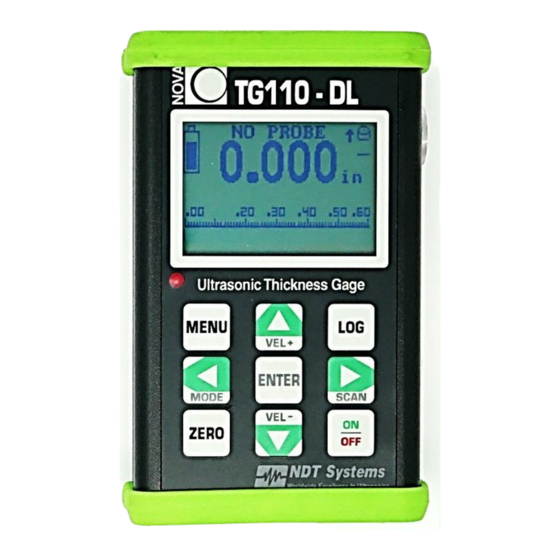
TG110DL User’s Manual 4. DEVICE REFERENCE Exterior Features, Controls, and Connections 1. ON / OFF Button 2. Up Arrow / Velocity + Button 3. Down Arrow / Velocity – Button 4. Left Arrow / Mode Button Enter Button 5. Right Arrow & B-Scan Start Button 6. -
Page 7: Button And Indicator Descriptions
LOG BUTTON: Access to the TG110DL’s data logging features. Use the LOG menu to start a NEW LOG (only choice of no other log exists), view an existing LOG, edit an existing LOG, ADD readings to an existing LOG or delete existing LOGs. - Page 8 TG110DL User’s Manual SCAN BAR & SCALE: The black bar at the bottom of the display is called a Scan Bar. This feature is unique to NDT Systems handheld thickness gauges. A visual representation of the measured thickness, as the thickness value changes the bar position across the screen changes.
-
Page 9: Main Menu Features
Adjust Scale The Scan Bar Scale is user adjustable and can start and end at any value within the TG110DL specifications. Suggested scale values might be 10% over the maximum value of expected thickness to be measured. For instance, if the material under test is never expected to exceed 0.500"... - Page 10 Also available in the SELECT PROBE menu is a library list of legacy NOVA Series transducers. These transducers were originally provided with the NDT Systems, Inc Nova 100D which has been available for many years. The items on this list allow you to use your existing investments in Nova series transducers. In time this list will be increased to support other transducers as well.
- Page 11 The NDT Systems TG-560P Through-Paint transducer is available separately or bundled with the TG-110DL (Order TG-110 PKG 560P).
- Page 12 Press ENTER to save the gauge velocity value to the displayed value. Press the LEFT/MODE button to return to the main measuring screen and begin taking measurements. NOTE: The TG110DL cannot be loaded with both the Through-Paint and Velocity software packages. 11 | P a g e NDT Systems, Inc.
-
Page 13: Data Logger
The data log file is named by moving this cursor through the alphanumeric field and pressing ENTER on each desired character. If no name is defined, the TG110DL will assign the next available numeric value by default. Press the menu button when finished naming the data log to return to the NEW LOG FILE menu. - Page 14 TG110DL User’s Manual ENTERING DATA: To enter a value in a data log, hold the transducer on the area of interest and press the ENTER key when the reading is stable. The value measured will be recorded in the currently flashing cell of the data log. To enter the next value, use the RIGHT or LEFT arrow buttons to move to a new cell and repeat the process above.
-
Page 15: Scrolling B-Scan
TG110DL User’s Manual 8. SCROLLING B-SCAN To activate the time encoded B-SCAN press the SCAN / RIGHT arrow button when the main measurement screen is active. A series of scrolling dots will appear, moving right to left. Along the left vertical axis is a scale value representing the thickness range value set for the SCAN BAR. -
Page 16: Preparationfor Use
Probe Attachment: All transducers except the “Mini-Probes” have a detachable dual cable for connecting to the TG110DL. Connect the dual cable (LMD1) to the probe using the cable end with the smaller red-sleeved and black- sleeved Microdot screw-on connectors (certain transducers may require attaching the red-sleeved and black- sleeved connectors to the correspondingly marked polarized connectors). - Page 17 TG110DL. These specially formulated couplants should be used whenever possible. Reference Samples: To calibrate the TG110DL, a known thickness or a known ultrasonic velocity for the material is needed. These calibration techniques require. at least initially, a reference sample representing the material to be gauged.
- Page 18 AUTO-SHUTOFF: The TG110DL automatically turns itself off approximately three minutes after non-use, thereby eliminating the need to use the OFF switch. To reset the turnoff timer, take a thickness reading or press the ENTER key.
-
Page 19: Calibration Procedures
TG110DL User’s Manual 10. CALIBRATION PROCEDURES With prior review of all other sections of this manual, use the following procedure to calibrate the TG110DL: 1 Connect the probe and cable to the gauge. 2 Momentarily depress ON/OFF to turn power on. -
Page 20: Gaging Tips & Techniques
TG110DL User’s Manual 11. GAGING TIPS & TECHNIQUES 1.Clean Surface: Prior to gaging, always remove performance hindering foreign substances from the material surface (e.g. dirt, loose scale, corrosion, particles, and flaking paint). 2.Excessive Surface Roughness: Very rough surfaces can cause erratic, extremely low or no thickness readouts. In such cases, consider scraping, sanding, grinding or filing the surface smooth enough to obtain a proper response (provided such a procedure and the amount of metal removal are acceptable). - Page 21 Use the smaller of the two minimum readings. Compound contours are difficult to gauge, so if successful results cannot be obtained, try using an ultrasonic flaw detector such as the NDT Systems Raptor or a thickness gauge with ‘A’ Trace capability such as NDT Systems' TG410.
-
Page 22: Gaging Precautions
Another effect, known as "pulse-envelope cycle-jumping," produces a reading somewhat larger than the actual thickness. It is advisable to double check critical thinner sections by using NDT Systems' NovaScope or an ultrasonic flaw detector such the Avenger EZ or Raptor. -
Page 23: Accessories
TG110DL User’s Manual 13. ACCESSORIES Standard Accessories: The standard TG110DL Kit contains the TG110DL gauge (batteries installed), TG-506 Probe, LMD1 Probe Cable, Plastic Couplant Bottle, Operating Manual. Optional Accessories: Detachable wrist strap, Flared Probe Holder, Accessory Carrying Case. Other accessories include Mini-Probes with top or side-mounted integral cables. - Page 24 TG110DL User’s Manual TG-502 SUBMINIATURE PROBE Dual-element, non-detachable side-mounted cable, 0.050 inch to 1.000 inch thickness range, 5 MHz, 0.22 inch diameter element, 0.28 inch tip diameter, 0.50 inch grip diameter by 0.75 inch high case. TG-502TM SUBMINIATURE PROBE Dual-element, non-detachable top-mounted cable, 0.050 inch to 1.000 inch thickness range, 5 MHz, 0.22 inch diameter element, 0.28 inch tip diameter, 0.40 inch grip diameter by 1.125 inch high case.
-
Page 25: Troubleshooting
TG110DL User’s Manual 14. TROUBLESHOOTING If you are experiencing issues with your TG110DL, please refer to the guide below for a list of potential problems and solutions. Factory Reset: If the gauge is running slowly, behaving erratically, or exhibiting another issue not included on the guide above, a factory reset may be recommended. -
Page 26: Warranty
TG110DL User’s Manual 15. WARRANTY NDT Systems, Inc. Standard Terms & Conditions including its Warranty Terms can be found at https://www.ndtsystems.com/standard-terms-conditions 25 | P a g e NDT Systems, Inc. 5542 Buckingham Drive Huntington Beach, CA 92649 PH: 714-893-2438... - Page 27 TG110DL User’s Manual APPENDIX 26 | P a g e NDT Systems, Inc. 5542 Buckingham Drive Huntington Beach, CA 92649 PH: 714-893-2438...
- Page 28 T G 1 1 0 - D T P W USERS MANUAL Version 2.0.7 TG110 Data Transfer Program for Windows NDT Systems, Inc. 5542 Buckingham Dr. Huntington Beach, Ca 92649 Ph. 714-893-2438 Fax. 714-897-3840 www.ndtsystems.com...
- Page 29 Table Of Contents Introduction Installing TG110-DTPW 2.0.1 Installation of USB Drivers 2.0.2 Installation of TG110-DTPW Running TG110-DTPW Getting Started 4.0.1 Settings 4.0.2 Specifications Transferring Data 5.0.1 Computer Polling – Manual Method 5.0.2 Computer Polling – Automatic Method 5.0.3 Down Loading Log Files From Your Gage Working With The Data 6.0.1 Clearing Data 6.0.2 Editing a Cell...
- Page 30 1.0 INTRODUCTION TG110-DTPW is designed to provide a simple means of transferring data from NDT Systems’ TG110 series gages to an IBM compatible computer running a Microsoft Windows operating system (XP, Vista, 7). TG110-DTPW will allow you to transfer data from TG110 gages and save it, along with other important report data.
-
Page 31: Getting Started
4.0 GETTING STARTED 4.0.1 Settings These fields are used to setup the communications between the computer and the Nova gage. COM Port: Using the drop down box, select the serial communications port that will be used. Receive Data Method: Using the drop down box, select the Receive Data Method that will be used. Computer Polling –... -
Page 32: Transferring Data
Inspector: You may use this field to record the name of the operator performing the inspection. Company: You may use this field to record the name of the company the inspection is being performed for. Notes: You may use these 2 fields to record notes about your inspection. Work order numbers, Procedure numbers, setup notes, etc. - Page 33 multiple lines by holding down your left mouse button and moving your mouse over all of the items you want to copy. You may also hold down the Ctrl key on your keyboard while clicking the items to copy. This allows you to choose individual lines to copy.
-
Page 34: Working With The Data
WORKING WITH THE DATA 6.0.1 Clearing All Data To clear out or delete all of the current data, click the Clear button. This will clear out all of the readings as well as the information in the Specifications area. 6.0.2 Edit a Cell This feature allows you to edit a cell in your grid. - Page 35 To Enable or Disable this feature, click Settings on the Menu Bar. Next, click on Copy to Clipboard. This will pop up a window to allow you to Enable or Disable this feature. 6.0.4 Saving Your Readings to a File To save your readings and Specifications information to disk, simply click on floppy disk icon or click File, then Save as.
-
Page 36: Printing A Report
6.0.6 Printing a Report The Print feature allows you to print a report on your printer containing all of your readings and specifications. The report will print on any of your Windows printers. A custom header can also be printed with all of your company contact information. To setup and save your company information, click Settings on the menu bar then click Company Setup. -
Page 37: Importing Data Into A Spread Sheet Program
6.0.7 Importing Data into a Spread Sheet Program The following example shows how to import your saved TG-110 Data file into Microsoft Excel. Load Excel and click on Open to open your file. Change the Files of Type to All Files (*.*) Then select your file to load. - Page 38 Next you need to select the delimiter type. Select Comma only. The Text Qualifier is Quotes (“). Next, if you choose, you can set the data type for the columns in your spread sheet. The default is General. Click on Finish to complete your Import.
- Page 39 The format for a Nova Data Transfer file is shown below: Line 1 = Software Version Line 2 = Log File Name Line 3 = Instrument Serial Number Line 4 = Transducer Line 5 =Part Number Line 6 =Inspector Line 7 = Company Line 8 = Notes Line 9 = Notes Line 10 = units...
-
Page 40: System Requirements & Contact Information
Line 13 and beyond = Data 7.0.3 Contact Information: NDT Systems, Inc. 5542 Buckingham Dr. Huntington Beach, CA 92649 To see the latest products and services from NDT Systems, inc., log on to www.NDTSystems.com or simply click on the NDT Systems, Inc. logo and your default web browser will be launched and take you to our web sight. -
Page 41: Licensing Agreement
Please read carefully the following terms and conditions. This agreement is made between the Purchaser, (hereinafter USER), and NDT Systems, Inc. (hereinafter NDT) for the licensing of TG-110-DTPW. TG-110-DTPW has only commercial use and the terms of this agreement including the disclaimers and limitations are expressly part of the bargain on which the license to use TG-110-DTPW is granted. -
Page 42: Usb Setup Addendum
USB Setup Addendum 5542 Buckingham Dr. • Huntington Beach CA 92649 (714) 893-2438 • FAX: (714) 897-3840... - Page 43 N D T S Y S T E M S I n c . Table of Contents 1. Introduction......................2 2. WIN98/SE Compatibility..................3 3. Windows XP Setup ....................4 3.1 Setup ........................4 3.2 Changing Port Number..................
-
Page 44: Introduction
N D T S Y S T E M S I n c . Introduction The NDT Systems USB interface is setup to identify different products while using the same USB controller. This means that only one driver installation package is needed for our full line of products. -
Page 45: Win98/Se Compatibility
N D T S Y S T E M S I n c . WIN98/SE Compatibility Windows 98 and 2000 are no longer supported by the drivers included on your CD. However, if you require the application to run on these platforms, email info@ndtsystems.com for help acquiring a legacy version of our software. -
Page 46: Windows Xp Setup
Drivers” on the CD (i.e. D:\USB Drivers), and run NDTCP210xVCPInstaller.exe. The dialog above will appear. Click Install to continue. If any previous versions of NDT Systems, Inc. drivers are on the computer, the above dialog will appear. Click Yes for the removal and installation to proceed. - Page 47 CD), then the Found New Hardware wizard will take you through loading the drivers, Step by Step. When you connect your NDT Systems instrument it will bring up the Found New Hardware wizard. If not, you will need to bring up the Device Manager. Open Start menu, then choose Run…...
- Page 48 N D T S Y S T E M S I n c . At the next screen you want to select Install from a list or specific location. Select include this location in the search. Then click the browse button. In the browse for folder box select your CD drive that has the driver disc in it.
- Page 49 N D T S Y S T E M S I n c . The path to the drivers folder should now be seen to the left of the browse button. If it is correct Click the Next button. The computer will begin reading in the driver files. NOVA-DTPW USERS MANUAL VER 105...
- Page 50 N D T S Y S T E M S I n c . After the wizard finishes the driver installation, it will display this screen. Click the Finish button. When it has finished the above message will show on the tool bar. To confirm installation and determine the ComPort assignment for your instrument follow the next series of steps.
- Page 51 N D T S Y S T E M S I n c . Bring up the Systems Properties dialog by clicking on the System Icon in the Control Panel area. Next select the Hardware tab. NOVA-DTPW USERS MANUAL VER 105...
- Page 52 N D T S Y S T E M S I n c . When the hardware tab is up click on the Device Manager button. NOVA-DTPW USERS MANUAL VER 105...
- Page 53 N D T S Y S T E M S I n c . The Device Manager lists all the available devices attached to your computer. NOVA-DTPW USERS MANUAL VER 105...
- Page 54 N D T S Y S T E M S I n c . Click the plus symbol next to the listing for Ports (COM & LPT). This will list all the Ports currently recognized on your computer. It also shows which COM or LPT port they are attached to.
-
Page 55: Changing Port Number
N D T S Y S T E M S I n c . Changing Port Number Click on the NDT Systems instrument listing to bring up its properties. If it is necessary to change the COM Port it is assigned to, click on the Port Settings tab. - Page 56 N D T S Y S T E M S I n c . Click on the Advanced Button. In the lower left is a box that shows the COM Port click the down arrow to show the available COM Ports. NOVA-DTPW USERS MANUAL VER 105...
- Page 57 N D T S Y S T E M S I n c . Select an available COM Port in the range of COM1 – COM15. Then click the OK button. Click OK at each level backing out. Make sure to note the COM port assignment made as you may need this in the DTPW application.
-
Page 58: Windows Vista/7 Setup
N D T S Y S T E M S I n c . Windows Vista / 7 Setup Automatic Installation After accepting any UAC prompts, proceed as specified above for Windows XP Automatic Installation. If older versions of drivers are installed, upgrading is necessary to ensure continued functionality. - Page 59 N D T S Y S T E M S I n c . Manual Installation If the instrument was to be connected to the USB first (before running the setup on the CD) or older, unsigned drivers were previously installed, then the Found New Hardware wizard will take you through loading the drivers, Step by Step.
- Page 60 N D T S Y S T E M S I n c . Choose “Browse my computer for driver software”. Type the drive letter of your CD drive (i.e. D:\) or browse to select it. Make sure “Include subfolders” is checked, then click Next. NOVA-DTPW USERS MANUAL VER 105...
- Page 61 N D T S Y S T E M S I n c . Windows should find the drivers on the disk and automatically proceed with installation. Once installation is complete you can close the window. Take note of the COM port your instrument has been assigned to, as this will be needed in the DTPW application.
Need help?
Do you have a question about the TG110DL and is the answer not in the manual?
Questions and answers