
Subscribe to Our Youtube Channel
Related Manuals for NDT Systems TG400


Summary of Contents for NDT Systems TG400
- Page 1 OPERATOR'S MANUAL TG400 Ultrasonic Thickness Gage Featuring: SplitView, SplitScan & AutoTrack NDT Systems, Inc. 17811 Georgetown Lane Huntington Beach, CA 92647 Phone: (714) 893-2438 FAX: (714) 897-3840 Rev. 1.0 07/06...
- Page 2 As you may have concluded, this manual contains a lot of various information. You do not necessarily have to read the whole manual in order to use the TG400. Much of the information is presented in a tutorial fashion to aid in the understanding of specific applications.
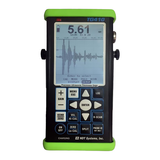
- Page 3 1.1 Specifications Display Super Twist LCD, 3.9" 240x320, transflective; backlit, contrast adjustable, battery status and mode icons, large thickness/soundpath display. Hollow or filled waveform, reversed field selectable. Display Mode RF; Positive Halfwave, Negative Halfwave, Full-wave rectified. Graticule Graphically Generated, 10 x 10 major divisions Receiver 0.5 to 25 MHZ Broadband, 1 Band Pass Filter Gain...
- Page 4 Battery Pack Discharge time - Up to 20 hours, typical, depending upon display back light usage. (3 ‘AA’ NiMH furnished) Battery Charger 5 hours for full charge. Transducer Cable Lemo Connectors. Connectors Size Top Section: 3.25"W x 7"L x 1.4"D Weight (Including Approximately 1 pounds (0.6kg) Battery Pack)
- Page 5 First, turn the TG400 off using the on/off key. If the unit won’t turn off in this manner, open the rear panel & remove and replace the battery cap. Next, press and hold the SEL key down and while holding this key down press the ON/Off key.
- Page 6 The TG400. For best results, use transducers from the OPTIMA line of transducers produced by NDT Systems, Inc. A free catalog will be sent on request by contacting Customer Information at NDT Systems, Inc., 17188 Georgetown Lane, Huntington Beach, CA 92647, phone (714) 893-2438, FAX (714) 897-3840.
-
Page 7: Menu Descriptions
2. MENU DESCRIPTIONS One of the significant features of the TG400 is the Direct Access Keypad. Velocity, Zero and Gain are just a single keystroke away. There are also 2 option keys. Opt2 is predefined as A-Trace split. Opt1 is reserved for future use. - Page 8 “ENTER TO SELECT” MAIN MENU (MENU/ESC Keypad Selection) The functions grouped in the MAIN menu are used to select TG400 basic setup parameters. These items are logically among the first to be addressed during a new setup. Last setup/factory default values are automatically displayed.
-
Page 9: Automatic Gain Control (Agc)
Damping to visually optimize the receiver / transducer performance AUTOMATIC GAIN CONTROL (AGC) A unique feature of the TG400 is the Automatic Gain Control. This control is is under hardware control and is fully automatic. The useful- ness of this feature would be evident on material with varied attenuation properties such as painted and non painted surfaces or corroded back surfaces. - Page 10 - HW - Negative half-wave rectified - HW when selected, displays only the negative portion of the RF signal on the A-trace display. FW - Fullwave rectified FW when selected, displays a superimposed -HW signal on a +HW signal on the A- trace display.
- Page 11 Measurement Time is a unique feature generally used in Delay Line Transducer Measurements. In the figure to the left we have used a standard NDT Systems, D11 Transducer. Currently the gage is triggering on the 2 delay line multiple which is of no value and could potentially cause operator confusion when actual measurements approach the delay end.
-
Page 12: Setup Menu
Saved transducer setups. PICK Use the Up & Down arrow to select transducer types. PICK recalls any ultrasonic setup stored in the TG400's memory. This includes User setup, Factory Default setup or any of the other 30 11 11... - Page 13 instrument setups. Note: If the gage is powered ON with the ENTER button depressed, the Factory Default setup will be loaded. 12 12...
-
Page 14: Transducer Selection
Set rectification HW+, HW-, RF or FW as desired. 3.0 TRANSDUCER SELECTION The TG400 is a capable precision thickness gage. Virtually any broad band or general purpose transducer (application dependant) used with the TG400, as can equivalent transducers produced by other manufacturers. - Page 15 ±0.0001 (±0.003mm). To achieve such accuracy, not only is it necessary to have an appropriate transducer, the thickness gaging instrument must have extremely stable, high speed electronic circuitry. TG400 fulfills this requirement admirably. For a procedure to demonstrate this capability, see Section 4.3.2.3, below.
- Page 16 This is useful, for example, in gaging remaining thickness over internal passages in turbine blades. Procedures for using immersion transducers are outlined in Section 4.3.2.4, below. Metals with Thicknesses Ranging from 0.030 inch (0.76mm) Upward. Single Element Contact Transducers Hard-Faced Wear Plates. Depending upon active element size and frequency, highly damped (broadband) transducers of this type can seldom be used on steel or aluminum much below 0.030 inch (0.8mm).
- Page 17 The ultrasonic instrument must provide the capability of isolating the pulser and receiver, as does the TG400. Practical minimum thickness resolution from a dual element transducer optimized for thickness gaging is approximately 0.040 inch (1.0mm).
- Page 18 4.0 TG400 SETUP AND OPERATING PROCEDURES. In designing the menus for the TG400, particular attention has been paid to simplifying the process of locating items, then prompting the operator to do something intuitive in order to change control settings. 4.2 FACTORY Setup Variables.
- Page 19 1.2 inch. However, note that T-readout did not change unless the gain was substantially increased. With TG400’s digital electronics, it is not necessary to use the graticule or other precise settings of range in order to calibrate for, and to readout precise thicknesses.
- Page 20 screen. Its purpose is to "block" the trailing edge echos associated with the initial pulse or any spurious signals which might interfere with what is known as the true interface. This group of echos contains ring-down echos from the transducer and "noise" accompanying stray reflections resulting from coupling.
- Page 21 ZERO & VELOCITY The next two functions, VEL and ZERO are adjustments necessary to "calibrate" the gage to the accurately measure the specific material under test. In our example, using a 0.500 inch thickness step, we have yet to perform any operations to "calibrate"...
- Page 22 A short-cut in the calibration routine for metals other than steel is to scroll the value at VEL to the nominal velocity for that material. Velocity values are tabulated in a variety of publications, including NDT Systems, Inc.' OPTIMA transducer catalog. NOTE: Tabulated velocity values have been obtained from a variety of sources that do not always agree.
- Page 23 For precision thickness gaging, the type of waveform used for setups has a significant effect on gaging results. Note that the RECT default is +HW, meaning that the current display is of signals that are positive half-wave rectified. Appropriate Selection of Echo Half cycle To better illustrate the effects produced by the various waveform displays, press MENU to return to the Main Menu.
- Page 24 "expand" the RF display. If, for example, for a 2 inch thick test specimen, the full-scale range of the TG400 has been set to a long range, and the RF display is selected, there will be poor detail in the presentation of the RF.
- Page 25 Procedures for Using Dual Element Transducers with Delay Lines. Dual element transducers combine the advantages of single element delay line transducers with the addition of a few more. The sound beam of a dual element transducer is generally directed into the test object at a small angle.
- Page 26 V-Path are corrected and linearized in software. Since each manufacturers V-Path factor can be different it is not possible to provide a full table of possible variations. In order to calibrate using an NDT Systems Probe (such as the TG506) follow the following simplified procedure:...
- Page 27 Option - A < Connect TG506 Transducer < From PROBE Menu, Select SINGLE or DUAL transducer < Press PROBE ID Key - The gage will recognize the attached transducer ad select the appropriate transducer from the list. < Press ZERO/ECHO front panel key. The gage will display the screen to the right, requesting you to place the probe on the ZERO Disc and then pressing the ENTER key.
- Page 28 Dual Element Multiple Echo Interval Measurement Procedure. With careful optimization and setup, multiple back echo intervals can be used for thickness measurement using dual element transducers. In the example shown to the right, multiple back echo intervals as far as the 4th back echo can be seen.
-
Page 29: B-Scan Setup
B-SCAN SETUP MENU Selections STOP SAVE Save as a user EDIT To Keyboard for user file naming and scan annotation RECALL BSCAN# Select Saved B-Scan from list EDIT Annotate and re-save a stored B-Scan GAIN Up or Down Arrow to adjust. Up or Down Arrow to adjust. - Page 30 Quick Start B-Scan Setup Assumptions: Stock Transducer - PX506 0.500" Thick Pipe/Plate Assembly: Connect and secure cable to Phoenix bottom Connect Lemo end to Scanner Assure transducer is flush to recessed into swivel sled. Recess should not be more than 0.004" This is about the thickness of 1 piece of scotch tape.
- Page 31 gage) and when you have a steady echo, press the ENTER key. This sets the probe Zero and any offset between the probe and surface under inspection. Place the probe on the 0.500"(or thicker) Step of the step block Select VEL on the Keypad, then use the Up & Dn arrow keys to adjust the Velocity. It should range between 0.2320 to 0.2350 in general terms for un-coated steel.
- Page 32 Thickness Gaging Procedures for Non-Metallic and Composite Materials. To some extent, all of the previously described procedures can be applied to thickness gaging of engineering materials other than metals. Because there are so many such materials, there will be no attempt in this manual to detail them.
-
Page 33: Battery Pack And Charger
The gage is charged via an external battery charger. Once fully charged the TG400 will run for up to 20+ hours before requiring another charge. Charge time is 6-8 hours for a full charge from empty. - Page 34 In addition to NDT Systems, Inc.' OPTIMA transducers, cables, reference standards and other transducer accessories, the following optional TG400 accessories are available: ATRP1 - TG400 Carry Pouch - A light-weight leatherette protective case. The TG400 fits firmly into a case like compartment supported at an adjustable angle stand. The integrated stand also snaps around a belt.
-
Page 35: Warranty
Purchaser's exclusive remedy will be the return of the purchase price for the instrument. The liability of NDT Systems, Inc. shall in no event be greater then the full amount of the purchase price for the instrument.
Need help?
Do you have a question about the TG400 and is the answer not in the manual?
Questions and answers