Table of Contents
Advertisement
Quick Links
FEATURES
▪ PIE-1 changes analog relay output signals (N.C.) to
original ASCII code.
▪ PIE-1 can supply power to detector using a PoE hub
or switch.
SAFETY PRECAUTION
▪ Follow all cautions and instructions in this manual
before installation.
▪ Keep this manual after installation so that you can
read when necessary.
▪ Remember the meanings of "Warning" and
"Caution" below to use the product safely.
If you ignore a warning, the user or other
Warning
people may be injured or dead.
If you ignore a caution, the user or other
Caution
people may be injured or the product or
something around it may be damaged.
▪ Do not repair, dismantle or modify the product
yourself.
▪ Do not touch the product with a wet hand.
▪ Be careful not to damage other interior wiring when
installing or wiring the product.
▪ Power off the product immediately if smoke, odor or
strange sound emits from the product.
▪ Do not install the product in an extremely moist place
such as a bathroom or a place where the product
may be wet.
▪ Insert the connectors securely when wiring.
CE Statement
Warning: This is a class A product. In a domestic
environment this product may cause radio interference
in which case the user may be required to take
adequate measures. (EN55022)
PoE IP Encoder
PoE IP Encoder
PIE-1
PIE-1
Warning
Warning
Caution
INSTALLATION INSTRUCTIONS
( for SIP series and RLS series )
PARTS IDENTIFICATION
1
Main unit of PIE-1
■
■
■ No. 6-32 UNC screw (5/8 inch), 6 pcs
■ Alarm 10-pin cable (26cm)
■ Alarm 6-pin cable (10cm)
■ Alarm 4-pin cable (10cm)
■ Power 2-pin cable (26cm)
■ Power 2-pin cable (10cm)
Be sure to use the attached cables.
▪
Do not use 12V and 24V power sources at the same time.
▪
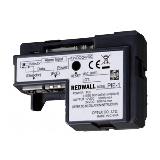
Connectors
Ethernet connector for detector
SIP mounting plate
■ Gasket sheet
for Gang Box
for Gang Box
Caution
Alarm input connector
12VDC Power output connector
24VDC Power output connector
Ethernet connector for PoE
No.5919420
Advertisement
Table of Contents

Related Manuals for Optex REDWALL PIE-1

Summary of Contents for Optex REDWALL PIE-1
- Page 1 No.5919420 INSTALLATION INSTRUCTIONS PoE IP Encoder PoE IP Encoder ( for SIP series and RLS series ) PIE-1 PIE-1 FEATURES PARTS IDENTIFICATION ▪ PIE-1 changes analog relay output signals (N.C.) to original ASCII code. ▪ PIE-1 can supply power to detector using a PoE hub or switch.
- Page 2 CONNECT PIE-1 TO THE SIP MAIN UNIT Step 1 (1) Prepare an appropriate Dual Gang Box. (2) Using an Allen key, detach the SIP base from the SIP main unit. Step 2 Step 3 Step 4 (1) Plug the alarm 10-pin cable to (1) Take off a rectangular gasket (1) Pass the alarm 10-pin PIE-1.
- Page 3 3. Enter the user ID and the password below. RESETTING User ID: PIE-1 Password: OPTEX If you forget the IP address you have set, reset it to 4. Change the IP address if necessary. obtain the default IP address in the following procedure.
- Page 4 TEL:+1-909-993-5770 Tech:(800)966-7839 URL:http://www.optexamerica.com/ OPTEX SECURITY SAS (FRANCE) TEL:+33-437-55-50-50 URL:http://www.optex-security.com/ Required power less than 25.5W, can use the PoE Plus Hub. OPTEX (EUROPE) LTD. (UK) TEL:+44-1628-631000 URL:http://www.optexeurope.com/ *Specifications may be modified without prior notice. OPTEX SECURITY Sp. z o. o. (POLAND) TEL:+48-22-598-06-55 URL:http://www.optex.com.pl/...
Need help?
Do you have a question about the REDWALL PIE-1 and is the answer not in the manual?
Questions and answers