
Related Manuals for Deltec CADD-Prizm PCS II 6101


Summary of Contents for Deltec CADD-Prizm PCS II 6101
- Page 1 This online version differs from the printed version. Certain information that is not intended for patients has been removed.
- Page 2 Smiths Medical MD, Inc. to see if a later revision of this manual is available. Technical Assistance If you have comments or questions concerning the operation of the Deltec CADD-Prizm ® PCS II pump, please call the number given below. When calling, please specify the pump’s software module.
-
Page 3: Warnings
® Read this entire Operator’s Manual before operating the Deltec CADD-Prizm PCS II ambulatory infusion pump. Failure to properly follow warnings, cautions, and instructions could result in death or serious injury to the patient. WARNINGS • This Operator’s Manual should be used by clinicians only. Do not permit... - Page 4 of medication and delivery accuracy required must be considered when using a syringe with the CADD ® pump. Clinicians must regularly compare the volume remaining in the syringe to the pump’s displayed values such as RES VOL and GIVEN in order to determine whether under-delivery of medication is occurring and if neces- sary, take appropriate action.
- Page 5 If you are using a Deltec administration set or medication cassette reser- voir that does not have the flow stop feature (reorder number does not ™...
- Page 6 delivery. • When you enter a new Max Doses per Hour value, any lockout time in effect will be cleared. A Demand Dose could be requested and delivered immediately upon starting the pump, resulting in over-delivery. • With the pump stopped and in LL0 ONLY: Entering a new Delivery Limit will reset the delivery limit feature.
-
Page 7: Cautions
CAUTIONS • To avoid damaging the pump’s electronics, do not operate the pump at temperatures below +2°C (36°F) or above 40°C (104°F). • To avoid damaging the pump’s electronics, do not store the pump at temperatures below -20°C (-4°F) or above 60°C (140°F). Do not store the pump with a Medication Cassette Reservoir or CADD ™... - Page 8 pump. Remove the pump from the patient during MRI procedures and keep it at a safe distance from magnetic energy. • Use of this pump on patients monitored by electronic equipment may cause artifactual interference. As with all electronic equipment, artifacts which affect the performance of other equipment, such as ECG monitors, can occur.
-
Page 9: Table Of Contents
Table of Contents WARNINGS CAUTIONS Section 1: General Description Introduction ................. Indications ................... Epidural/Subarachnoid Administration ........1.3.1 Analgesics ................ 1.3.2 Anesthetics ..............Symbols ..................Pump Diagram ................Description of the Keys, Display and Features ......1.6.1 Indicator Lights ..............1.6.2 Display with backlighting ..........1.6.3 Keypad ................ - Page 10 Unlocking the Pump Program to LL0 .......... 2.3.1 To unlock the pump program using the Cassette / Keypad Lock Key ................. 2.3.2 To unlock the pump using the keypad ....... 18 Programming the Pump: General Instructions ......2.4.1 Messages you may see during programming ....2.4.2 Before Beginning Programming ........
- Page 11 2.14.1 To attach the Remote Dose Cord ........2.14.2 To detach the Remote Dose Cord ........2.15 Starting the Pump ................ 2.16 Adjusting Patient Delivery (Titration) .......... 2.16.1 Titrating while the pump is running ......... Section 3: Operating the Pump Stopping the Pump ..............
- Page 12 Section 5: Biomed Toolbox Overview: Accessing the Biomed Toolbox ........5.1.1 To Access the Biomed Toolbox Menu ....... 67 Custom Concentrations ..............68 Dosing Limits ................69 Delivery Limit ................Program Limits ................Maximum Delivery Rate ............. Key Beeps ..................Res Vol Trip Point ................
- Page 13 Section 6: Reference & Troubleshooting Troubleshooting ................Alarms and Messages, Alphabetical List ........90 Cleaning the Pump and Accessories ..........6.3.1 Cleaning the Battery Contacts .......... 100 Exposure to Radiation or Magnetic Resonance Imaging (MRI) ... 101 Continuous Rate Scroll Ranges ............ 102 Demand Dose, Clinician Bolus Scroll Ranges: Milliliters .....
-
Page 15: Section 1: General Description
Section 1: General Description Section 1: General Description 1.1 Introduction The Deltec CADD-Prizm ® PCS II (Pain Control System) ambulatory drug delivery system provides measured drug therapy to patients in hospital or outpatient settings. Therapy should always be overseen by a physician or a certified, licensed healthcare professional. - Page 16 Section 1: General Description patient injury or death. To prevent the infusion of drugs that are not indicated for epidural space or subarachnoid space infusion, DO NOT use administration sets that incorpo- rate injection sites. The inadvertent use of injection sites for infusion of such drugs may cause serious patient injury or death.
-
Page 17: Symbols
Section 1: General Description 1.4 Symbols Alternating Current Accessory Jack Attention, consult accompanying documents (read Instructions for Use) Class II Equipment Type CF Equipment Splashproof - water splashed against pump housing will have no harmful effects (see Cleaning the Pump and Accessories, Section 6, for additional important information) Date of Manufacture Catalog (reorder) number... -
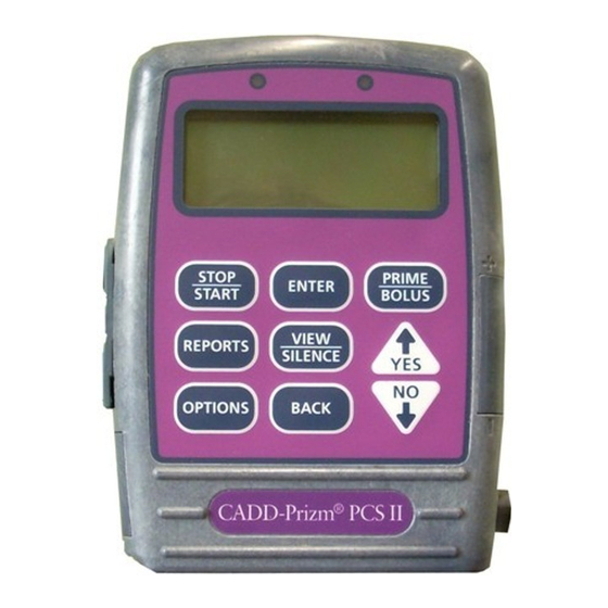
Page 18: Pump Diagram
Section 1: General Description 1.5 Pump Diagram Indicator Lights Amber Green Display Keypad ‹ ⁄ ¤ ´ Œ „ Î Power jack Å Í Data In/Out jack Front View Air Detector Port Cover P C S I I ® - P r i z m C A D D Air Detector (optional) -
Page 19: Description Of The Keys, Display And Features
Section 1: General Description 1.6 Description of the Keys, Display and Features 1.6.1 Indicator Lights When the pump is being powered the indicator light flashes. Green: The green light flashes to indicate that the pump is running and delivering fluid as programmed. Amber: The amber light flashes when the pump is stopped or an alarm condition exists. -
Page 20: Power Jack
Section 1: General Description „ is used to view the programming screens without changing the setting or value displayed. It is also used to return from the Options Menu to the main screen, from the Reports menu to the main screen, or from the Biomed Toolbox Menu to the Options Menu. -
Page 21: Cassette
Section 1: General Description sounds and delivery stops. (See Section 6 for Air Detector specifications.) The pump may be customized to require an Air Detector (see Section 5, Biomed Tool- box). If an Air Detector is attached but not required, it may be turned off (see Section 4, Options). -
Page 22: Cassette / Keypad Lock
Section 1: General Description 1.6.12 Cassette / Keypad lock This allows you to secure the cassette to the pump using the key provided. The cassette must be latched before it can be locked. The Cassette/keypad lock also works together with the AutoLock feature to lock or unlock the pump program (see Lock Levels, this section, for more information). -
Page 23: The Main Screen
Section 1: General Description 1.7 The Main Screen The main screen is the starting point for programming or viewing the pump’s settings. The main screen may be customized in the Biomed Toolbox (see Custom Main Screen, Section 5). The following information may be displayed: Active delivery mode (Epidural displayed if turned on, or 21... -
Page 24: Lock Levels
Section 1: General Description 1.8 Lock Levels Lock levels are used to limit patient access to certain programming and operat- ing functions. The table on the next page lists the functions that are accessible in LL0 (Lock Level 0 - pump program and keypad completely unlocked), LL1 (Lock Level 1 - limited access to pump program and keypad), and LL2 (Lock Level 2 - minimal access to pump program, keypad is locked). -
Page 25: Lock Level Tables
Section 1: General Description 1.9 Lock Level Tables These tables list the operations that are accessible in each lock level while the pump is stopped and running. LL0 permits complete access to all programming and operating functions. LL1 permits limited access to pump programming and operations. - Page 26 Section 1: General Description Stopped Running Pump Options Yes, Biomed Toolbox w/code Lock Level Yes* Yes* Yes* Yes* Yes* Yes* View View Epidural Mode only only View View Units only only View View Time only only View View Date only only View View...
-
Page 27: Section 2: Pump Setup And Programming
Section 2: Pump Setup and Programming Section 2: Pump Setup and Programming 2.1 Installing the Battery Use a new, 9 volt alkaline or lithium battery such as the DURACELL ® Alkaline ® ® MN 1604, the EVEREADY ENERGIZER Alkaline #522 or the ULTRA- LIFE ®... -
Page 28: To Install A Battery
Section 2: Pump Setup and Programming 2.1.1 To install a battery w/Button» 1. Make sure the pump is stopped. Press the button on the battery door and slide the battery door forward. Remove the used battery. 2. Match the + and – markings on Match the new battery with the mark- tery»... -
Page 29: Power Up
Section 2: Pump Setup and Programming 2.2 Power Up When you install a battery or turn the pump indicators on by pressing any key on the keypad, the pump will start its power up sequence during which it performs self-tests, may display programmed values and, if turned on in the Biomed Toolbox, allows you to program a New Patient Marker. -
Page 30: If Biomed Toolbox Is Set To Clear Program In Power Up
Section 2: Pump Setup and Programming • An event is added to the Event Log. • The Pain Scale Log, Delivery Log, Doses Hour by Hour, and Patient Review Log are cleared. • Given is cleared. • Doses Attempted and Doses Given are cleared. •... - Page 31 Section 2: Pump Setup and Programming • Records and lockouts are cleared, as described in 2.2.1, above. • Concentration (if units are milligrams or micrograms) defaults to the highest value (100 mg/ml or 500 mcg/ml, or highest value not customized to “Off” in Custom Concentrations in Biomed Toolbox), and must be confirmed.
-
Page 32: Unlocking The Pump Program To Ll0
If you are using a Deltec administration set or medication cassette reservoir that does not have the flow stop feature (reorder number does not start with 21-73xx): you must use a CADD ™... -
Page 33: Programming The Pump: General Instructions
Section 2: Pump Setup and Programming NOTE: If <Enter Custom Code> appears on the screen, the Lock Level Code has been customized. Enter the custom Lock Level Code in the next step. ´ Lock Level Code Î 3. Press until the Lock Level ** Text Omitted ** Code To Unlock Keypad... -
Page 34: Messages You May See During Programming
Section 2: Pump Setup and Programming The procedure for changing a programmed setting is similar for most program- ming screens. The following example of the Reservoir Volume screen illustrates the typical features of a programming screen: • Make sure the pump is stopped and in Lock Level 0 (pump pro- gram and keypad completely unlocked). -
Page 35: Reports Key
Section 2: Pump Setup and Programming Œ REPORTS Key Œ key is used to access a variety of reporting and record-keeping functions. The reports menu can be customized in the Biomed Toolbox by enabling (or turning on) only those reports that you are interested in. Access to reports is dependent on the pump’s Lock Level (see Lock Level Tables at the end of Section 1). -
Page 36: Given
Section 2: Pump Setup and Programming ¤ 2. Press to clear the dose counters. Dose Counters Given/Attempt: 0/ 0 since 01/01/00 07:14 2.5.2 Given <Clearing...> This screen appears if it has been turned on in the Biomed Toolbox, and shows the total amount of fluid delivered since the time and date indicated, which is the last time the value was cleared manually, or by adding a New Patient Marker. -
Page 37: Patient Review
Section 2: Pump Setup and Programming 2.5.4 Patient Review This screen appears if it has been turned on in the Biomed Toolbox, and allows you to review a summary of the pump’s current settings, and the number of doses given and attempted, beginning at a date and time (no longer than 48 hours) that you program. -
Page 38: Pain Scale Log
Section 2: Pump Setup and Programming 2.5.6 Pain Scale Log The Pain Scale Log appears if it has been turned on in the Biomed Toolbox, and displays all Pain Scale entries since the last time a New Patient Marker was added. -
Page 39: Event Log
Section 2: Pump Setup and Programming 2.5.8 Event Log The Event Log appears if it has been turned on in the Biomed Toolbox, and records the following types of events: hourly given totals, dose delivery, alarms, errors, power source changes, cassette changes and changes to pump program- ming or settings. -
Page 40: In Reports Menu
Section 2: Pump Setup and Programming ´ Pressing will cause the following to occur: • An event is added to the Event Log. • The Pain Scale Log, Delivery Log, Doses Hour by Hour, and Patient Review Log are cleared. •... - Page 41 Section 2: Pump Setup and Programming • Records and lockouts are cleared, as described in 2.5.9.1, above. • Concentration (if units milligrams or micrograms) defaults to the highest value (100 mg/ml or 500 mcg/ml, or highest value not customized to off in Custom Concentrations in Biomed Tool- box), and must be confirmed.
-
Page 42: Delivery Methods
Section 2: Pump Setup and Programming 2.6 Delivery Methods The pump provides the following methods of delivery: • Continuous Rate • Demand Dose, activated by the patient • Clinician Bolus, activated by the clinician. You may program each of the methods individually or in combination. The following graph illustrates the combined delivery methods. -
Page 43: Programming Screens
Section 2: Pump Setup and Programming 2.7 Programming Screens These are the programming screens. Descriptions of the screens follow. If Units programming is set as part of Options menu or as part of Biomed Toolbox (see Biomed Toolbox, Section 5), you may want to view and/or change Units (milliliters, milligrams or micrograms), in the Option menu or Biomed Toolbox (see Section 4, Options or Section 5, Biomed Toolbox) before beginning pro- gramming. -
Page 44: Units (If Applicable)
Section 2: Pump Setup and Programming Set Delivery Limit Set 1 hour limit 1.00 mg <Range: 1-100000 mg> Reservoir Volume Reservoir Volume 10.0 ml <Range: 1 - 9999> Air Detector Required Air Detector (review) <Review Only> 2.7.1 Units (if applicable) The Biomed Toolbox allows you to program the display so that Units appears as part of the Options menu, the Biomed Toolbox menu or here as part of the programming screens. -
Page 45: Demand Dose
Section 2: Pump Setup and Programming The maximum rate may be limited by the settings made in the Program Limits section of the Biomed Toolbox. 2.7.4 Demand Dose Enter the amount of drug to be delivered when the patient presses the Remote Dose Cord button. -
Page 46: Reservoir Volume
Section 2: Pump Setup and Programming frame is programmable from 1 to 12 hours in the Biomed Toolbox. This feature limits the amount delivered by the Continuous Rate and Demand Dose, but does not limit the amount delivered by a Clinician Bolus. When the limit is reached, the pump automatically begins to deliver fluid at the preset KVO rate for a minimum of 5 minutes. -
Page 47: Programming Example
Section 2: Pump Setup and Programming 2.8 Programming Example Medication is provided in a 100 ml Medication Cassette Reservoir at a concen- tration of 1.0 mg/ml. The patient should receive medication continuously at 5.0 mg/hr. Patient-activated doses of 2.5 mg are allowed, with a 15 minute lockout time between doses, and a Delivery Limit of 100 mg in 4 hours. - Page 48 Section 2: Pump Setup and Programming 3. Enter the Concentration of the drug This screen will not appear if the units are milliliters; go to step 4. ´ Î • Press to select the Concentration desired concentration. (If you 1.0 mg/ml cannot select the desired concen- tration, it may have been turned <Range: 0.1 - 100>...
- Page 49 Section 2: Pump Setup and Programming the dose because the Units or Concentration was changed, or the dose is greater than or equal to 100 ´ mg or mcg. Press to confirm, Î or press and re-enter the dose. NOTE: The pump will not allow you to scroll the dose outside the range displayed.
- Page 50 Section 2: Pump Setup and Programming only numbers within the range will appear. Max Doses Per Hour ´ Î • Press to select the maximum number of doses per hour. <Range: 1 - 4> ¤ • Press WARNING: When you enter a new Max Doses per Hour value, any lockout time in effect will be cleared.
- Page 51 Section 2: Pump Setup and Programming ´ • Press to confirm the change Change 4 Hr Limit to and clear accumulated limit 100 mg & clear value. accumulated limit? Press YES or NO NOTE: It may take a moment before the change is entered, as data in pump memory must first be cleared.
-
Page 52: Removing A Cassette
Section 2: Pump Setup and Programming 2.9 Removing a Cassette WARNING: Per general rules of safe practice, always clamp tubing before removing the cassette from the pump. Removing the cassette without closing the clamp could potentially cause unregulated gravity infusion, which could result in patient injury or death. -
Page 53: Attaching A Cassette
Section 2: Pump Setup and Programming 2.10 Attaching a Cassette Obtain a new, filled Medication Cassette Reservoir, or CADD ™ Administration Set attached to a nonvented, flexible IV bag. Refer to the instructions for use supplied with the product for information on preparing the product for use. Before attaching a new cassette, install a battery or turn pump indicators on as appropriate. - Page 54 «Prizm Latched & Locked» patient. If you are using a Deltec administration set or medica- Latch tion cassette reservoir that does not have the flow stop feature (reorder number does not start with 21-73xx): you must use a CADD ™...
- Page 55 Section 2: Pump Setup and Programming 6. The message “Cassette Locked” will Cassette Locked „ appear on the display. Press VIEW to continue 7. “Reset Reservoir Volume to...?” may Reset Reservoir appear. Volume to 100.0 ml? • To reset Reservoir Volume to the Press YES or NO ´...
-
Page 56: Priming The Tubing And Connecting To The Patient
Section 2: Pump Setup and Programming 2.11 Priming the Tubing and Connecting to the Patient Prime the tubing before connecting it to the patient’s infusion set or indwelling catheter. The pump must be stopped and in LL0 (pump program and keypad completely unlocked) or LL1 (limited access to pump program and keypad) to use the priming feature. - Page 57 Section 2: Pump Setup and Programming WARNING: Ensure that the entire fluid path is free of all air bubbles before connecting to the patient to prevent air embolism. Air embolism could result in serious patient injury or death. NOTE: If the fluid path contains an air eliminating filter, it is acceptable for air bubbles to be present on the vent side of the filter.
-
Page 58: Inserting The Tubing Into The Air Detector
Section 2: Pump Setup and Programming 2.12 Inserting the Tubing into the Air Detector WARNING: When the Air Detector is not installed, or is installed but turned off, the pump will not detect air in the fluid path. It is recommended that you periodically inspect the fluid path and remove any air to prevent air embolism. -
Page 59: Locking The Pump Program For The Patient
Section 2: Pump Setup and Programming 2.13 Locking the Pump Program for the Patient The Lock Level must be reset to LL1 (limited access to pump program and keypad) or LL2 (minimal access to pump program, keypad is locked) to pre- vent the patient from having complete access to all programming and operating functions. - Page 60 Section 2: Pump Setup and Programming WARNING: Do not disclose to the patient the pump’s security codes or any other information that would allow the patient complete access to all program- ming and operating functions. Improper programming could result in serious patient injury or death.
-
Page 61: Remote Dose Cord
Section 2: Pump Setup and Programming 2.14 Remote Dose Cord The patient uses the button on the Remote Dose Cord to start a Demand Dose. For easy access, the Remote Dose Cord may be fastened to the patient’s cloth- ing or bed sheet with the attached clip. WARNING: Do not place the Remote Dose Cord where the button might accidentally be pushed. -
Page 62: Starting The Pump
Section 2: Pump Setup and Programming 2.15 Starting the Pump 1. This is the last screen to appear when Start the Pump? you latch and lock a cassette. If the fluid path is free of air and the tubing ´ is attached to the patient, press Press YES or NO to start the pump. -
Page 63: Adjusting Patient Delivery (Titration)
Section 2: Pump Setup and Programming 2.16 Adjusting Patient Delivery (Titration) If the prescription allows, the Continuous Rate, Demand Dose and Delivery Limit can be easily adjusted (titrated) during the course of therapy. Titration can be accomplished in LL1 (limited access to pump program and keypad) while the pump is stopped, and in LL0 (pump program and keypad completely unlocked) or LL1 while the pump is running. - Page 64 Section 2: Pump Setup and Programming to relock the cassette to relock the pump program (or, change the Lock Level setting in the Options menu.) To Purchase, Visit Avobus.com or call 1-800-674-3655...
-
Page 65: Section 3: Operating The Pump
Section 3: Operating the Pump Section 3: Operating the Pump 3.1 Stopping the Pump Stopping the pump stops delivery. “STOPPED” will appear on the main screen and the amber indicator light will blink. 3.1.1 To stop the pump ⁄ Stop the Pump? 1. -
Page 66: To Start The Pump
Section 3: Operating the Pump main screen, and the green indicator light will blink. If the pump will not start, a message will appear on the display. Refer to the Messages and Alarms Table in Section 6. 3.2.1 To start the pump ⁄... -
Page 67: Starting A Clinician Bolus
Section 3: Operating the Pump 3.3 Starting a Clinician Bolus A Clinician Bolus may be delivered while the pump is running. It allows you to deliver a specified amount of drug, for example, as a loading dose. Lockout settings have no affect on Clinician Bolus frequency. However, a Clinician Bolus cannot be started while a Demand Dose is in progress. - Page 68 Section 3: Operating the Pump than or equal to 100 mg or mcg, a screen will appear asking you to ´ confirm the value. Press to con- Î firm, or to re-enter the value. Clinician Bolus 7. The screen will show the amount 10.00 mg decreasing as the bolus is delivered.
-
Page 69: Starting A Demand Dose
Section 3: Operating the Pump 3.4 Starting a Demand Dose If a Demand Dose has been programmed, the patient may start a Demand Dose while the pump is running. The amount delivered is added to the amount provided by the Continuous Rate. Each time the patient requests a Demand Dose, the pump will automatically add it to the Dose Counters screen. - Page 70 Section 3: Operating the Pump As the Demand Dose is delivered, the * PCS XXXXX main screen will show “DOSING” in Low Battery DOSING place of “RUNNING.” Res Vol 47.0 ml Press VIEW to advance...
-
Page 71: Stopping A Demand Dose Or Clinician Bolus
Section 3: Operating the Pump 3.5 Stopping a Demand Dose or Clinician Bolus A Demand Dose or Clinician Bolus can be stopped in progress. The pump may be in any lock level. A Demand Dose that has been stopped will remain recorded on the Dose Counter screen under “Given/Attempt.”... -
Page 72: Resetting The Reservoir Volume
Section 3: Operating the Pump 3.6 Resetting the Reservoir Volume 3.6.1 Resetting Reservoir Volume without changing the cassette Normally, when you latch and lock a cassette onto the pump as described in Section 2, a series of messages lead you through resetting the Reservoir Vol- ume, priming the tubing, (except in LL2), and starting the pump. -
Page 73: Section 4: Options
Section 4: Options Section 4: Options 4.1 Overview: Accessing Options The Options menu allows access to other pump features and settings. • If the pump is stopped the availability of an option may depend on Biomed Toolbox settings, the presence of an air detector and whether the pump program is locked or unlocked. -
Page 74: Lock Level
Section 4: Options 4.2 Lock Level You may view or program the pump’s lock status at any time, with the pump running or stopped, from the Options Menu if the Autolock feature is not in use. If you wish to use the AutoLock feature, see Section 5, Biomed Toolbox. 4.2.1 To change Lock Level Å... -
Page 75: Epidural Mode
Section 4: Options 4.3 Epidural Mode Reservoir latched When the Epidural Mode Option is turned On, Is epidural reservoir and a cassette is attached to the pump or the attached? pump is powered up with a cassette attached, one Press Yes or No of the messages at right appears in the display. -
Page 76: To Turn Epidural Mode On Or Off
Section 4: Options 4.3.1 To turn Epidural Mode On or Off Å Options Menu 2. Press | Epidural Mode ´ Î Å Press until “Epidu- ¤ Press § or fl or ENTER ral Mode” appears. Then press ´ Î 3. Press to select the desired Epidural Mode ¤... -
Page 77: Time
Section 4: Options the Units screen will display “custom” if two units have been selected in the Units Selection feature. The scroll range on the Units screen will include only the selected units. 4.5 Time The Time Option shows the time of day in 24-hour (military) time according to the pump’s internal clock. -
Page 78: Date
Section 4: Options ´ 4. Press to confirm the change. Change Time to 15:45? NOTE: It may take a moment before the change is entered, as data in pump Press YES or NO memory must first be cleared. Watch for <Entering> to appear at the bottom of the screen. -
Page 79: Air Detector On/Off
Section 4: Options ´ Î 3. Press to select the date, Date ¤ then press | 03/01/00 Press § or fl or ENTER Change Date to ´ 4. Press to confirm the change. 03/01/00? Press YES or NO NOTE: It may take a moment before the change is entered, as data in pump memory must first be cleared. -
Page 80: To Change The Air Detector Setting
Section 4: Options 4.7.1 To change the Air Detector setting To view the setting, the pump may be in any lock level. To change the setting, the pump must be stopped and in LL0 (pump program and keypad completely unlocked). Options Menu Å... -
Page 81: Section 5: Biomed Toolbox
Section 5: Biomed Toolbox Section 5: Biomed Toolbox 5.1 Overview: Accessing the Biomed Toolbox The Biomed Toolbox contains pump configurations that are less frequently changed. The Biomed Toolbox is accessible only when the pump is stopped and unlocked. 5.1.1 To Access the Biomed Toolbox Menu Å... -
Page 82: Custom Concentrations
Section 5: Biomed Toolbox 5.2 Custom Concentrations This screen allows you to select the concentrations that will be available for programming in the Concentration screen (mg/ml or mcg/ml). You may turn on or turn off all concentrations, except the currently programmed concentration. Then you can selectively turn on or turn off individual concentrations. -
Page 83: Dosing Limits
Section 5: Biomed Toolbox 5. Turn individual concentrations on or off as appropriate: ´ Î • Press to select the concentration. Select Concentration ¤ 2.0 mg/ml Off • Press to turn the concentration on or off. ENTER to turn on •... -
Page 84: Delivery Limit
Section 5: Biomed Toolbox The new setting is entered. Dosing Limit Delivery Limit <Entering...> 5.4 Delivery Limit If you have selected Delivery Limit in Dosing Limit (above), this screen will appear. The Delivery Limit feature limits the amount that can be delivered by the Continuous Rate and Demand Dose in a programmable 1 to 12 hour period. -
Page 85: Maximum Delivery Rate
Section 5: Biomed Toolbox 1. At the Biomed Toolbox Menu, press Biomed Toolbox Menu Î ´ until “Program Limits” | Program Limits appears. Press § or fl or ENTER ¤ 2. To change the setting, press Max Demand Dose Î ´... -
Page 86: Key Beeps
Section 5: Biomed Toolbox 5.7 Key Beeps This screen allows you to turn off the audible beep which accompanies each key press. This feature does not turn off any audible alarms associated with alarm or alert conditions of the pump. The default setting is On. Biomed Toolbox Menu 1. -
Page 87: Res Vol Empty Alarm
Section 5: Biomed Toolbox Change Res Vol Trip ´ 3. Press to confirm change. Point to 10 ml? Press YES or NO Biomed Toolbox Menu | Titration Limit Press § or fl or ENTER 5.9 Res Vol Empty Alarm The Res Vol Empty Alarm allows you to select either a Single or Insistent alarm when the Res Vol is empty. -
Page 88: Titration Limit
Section 5: Biomed Toolbox pump is powered down or the indicators are turned off. When Beep is selected the pump will beep every 5 minutes. The default is Beep. Biomed Toolbox Menu 1. At the Biomed Toolbox Menu, press ´ Î... -
Page 89: Autolock
Section 5: Biomed Toolbox 5.12 AutoLock The AutoLock feature automatically changes the Lock Level from LL0 to LL1 or LL2 when the pump is started, instead of requiring you to manually change the Lock Level. AutoLock may be set to LL1 Key/Code, LL2 Key/Code, LL1 No Key, LL2 No Key or “Not in Use.”... -
Page 90: Pm (Preventive Maintenance) Reminder
Section 5: Biomed Toolbox ¤ 2. Press . The current AutoLock AutoLock setting will appear. | LL1 Key/Code • To leave the setting unchanged and Press § or fl or ENTER return to the Biomed Toolbox menu, ¤ Change AutoLock to press LL1 Key/Code? ´... -
Page 91: Custom Clinician Code
Section 5: Biomed Toolbox ** Text omitted ** also changes the Biomed Toolbox Code to It does not affect the Clinician Bolus Code. 1. At the Biomed Toolbox Menu, press Biomed Toolbox Menu ´ Î until “Custom Lock” | Custom Lock œ... -
Page 92: Units Selection
Section 5: Biomed Toolbox 5.16 Units Selection Units Selection allows you to select which programming units you want to appear in the Programming Units screens. If you disable all but one set of programming units, the Programming Units will not appear. You cannot disable the programming units that is currently in use on the pump. -
Page 93: Programming Units
Section 5: Biomed Toolbox box” to have it be part of the Biomed Change Units Location Toolbox menu or “Program” to have it to Options? be part of the pump’s normal program- ming screens. Press YES or NO ´ 3. Press to confirm the change. -
Page 94: Date Format
Section 5: Biomed Toolbox 5.19 Date Format This screen allows you to select the date format. The date can be set to display in US Standard format (month/day/year) or in European Standard format (day/ month/year). Biomed Toolbox Menu 1. At the Biomed Toolbox Menu, press | Date Format ´... -
Page 95: Auto Review
Section 5: Biomed Toolbox In the Power Source display screen, only one box will be checked. To select ¤ the between them, press (Low 9V is the default setting). NOTE: To leave a Biomed Toolbox „ setting unchanged, press 5.21 Auto Review Auto review allows you to select the automatic program review feature, which would be displayed during the pump’s power up sequence. -
Page 96: To Access The Custom Reports Screens
Section 5: Biomed Toolbox 5.22.1 To access the Custom Reports Screens 1. At the Biomed Toolbox Menu, press Biomed Toolbox Menu ´ Î until “Custom Report” | Custom Report appears. Press § or fl or ENTER 2. To enter the Custom Reports screens, ¤... -
Page 97: Pain Scale
Section 5: Biomed Toolbox ered and total Given starting at a time and date within the last 48 hours that you specify. Custom Reports ¤ 1. Press to turn the Patient Review | Patient Review On report function on or off. ENTER to turn Off 5.22.1.5 Pain Scale The Pain Scale allows the Clinician and/or patient to enter a pain scale... -
Page 98: New Patient Marker
Section 5: Biomed Toolbox events in order starting from the most recent through the last 500 events. ¤ Custom Reports 1. Press to turn the Event Log | Event Log report function on or off. ENTER to turn On 5.22.1.9 New Patient Marker The New Patient Marker feature is configured in the Biomed Toolbox (see Section 5.16). - Page 99 Section 5: Biomed Toolbox Clearing the program (either in the Reports menu, as part of the pump’s power up routine, or both), causes the following to occur: • Adds an event to the Event History Log • Previous records and lockouts are cleared (see above) •...
-
Page 100: To View Or Change The New Patient Marker Function
Section 5: Biomed Toolbox Marker will be logged in the Event Log, and the program will be cleared. The New Patient Marker feature will not appear as part of the pump’s power up routine. • Option 4 Power Up/Clear - this means that the New Patient Marker feature will be available as part of the pump’s power up routine. -
Page 101: Upstream Sensor On/Off
Section 5: Biomed Toolbox 5.24 Upstream Sensor On/Off The Upstream Occlusion Sensor screen can be set to on or off. If this screen is set to on, and an upstream occlusion (between pump and fluid container) is detected, an alarm will sound, delivery will stop, and the display will show “Upstream Occlusion.”... -
Page 102: Air Detector Requirement
Section 5: Biomed Toolbox 5.25 Air Detector Requirement The Air Detector screen can be set to “Required” or “Not Required.” If this screen is set to “Required,” an Air Detector must be installed and active in order to start the pump; however, the pump may be programmed without an Air Detector. -
Page 103: Section 6: Reference & Troubleshooting
Section 6: Reference & Troubleshooting Section 6: Reference & Troubleshooting 6.1 Troubleshooting A continuous two-tone alarm is sounding; the amber light is lit or flashing. Delivery has stopped. Read the message on the display and refer to the list of messages beginning on the next page. - Page 104 Section 6: Reference & Troubleshooting concentration on (Section 5). Or, the concentration may not be programmable (see scroll range tables, this section).
-
Page 105: Alarms And Messages, Alphabetical List
Section 6: Reference & Troubleshooting 6.2 Alarms and Messages, Alphabetical List Messages and Alarms Description / Corrective Action The battery power is too low to operate the pump. 9 volt Battery Depleted / „ The pump is now stopped. Press to silence the Install good battery alarm. - Page 106 Section 6: Reference & Troubleshooting Messages and Alarms Description / Corrective Action AC Adapter Unpowered / The AC Adapter is not receiving power from the wall Check power source outlet. The 9 volt battery is powering the pump. Press „ to silence the alarm.
- Page 107 Section 6: Reference & Troubleshooting Messages and Alarms Description / Corrective Action All concentrations cannot be At least one concentration must be turned on when „ customizing concentrations. Press , then enable a turned off concentration. Cable Removed The cable was detached from the Data In/Out jack. „...
- Page 108 Section 6: Reference & Troubleshooting Messages and Alarms Description / Corrective Action A Clinician Bolus may not be started while a Demand Clinician Bolus not available Dose is being delivered. Wait until the Demand Dose during Demand Dose finishes, then start the Clinician Bolus if appropriate. Clock Battery needs service The clock battery must be replaced soon.
- Page 109 Section 6: Reference & Troubleshooting Messages and Alarms Description / Corrective Action The 9 volt battery does not provide sufficient power Delivery Too Slow / to support the programmed delivery rate. Connect an External power source external source of power. Or, if appropriate, acknowl- must be connected edge the message and allow delivery to proceed at the „...
- Page 110 Section 6: Reference & Troubleshooting Messages and Alarms Description / Corrective Action The AC Adapter is not receiving power or the power Insufficient External Power pack is completely depleted. Ensure the cords and Check Power Source cables are properly attached. Or, begin recharging the power pack.
- Page 111 Section 6: Reference & Troubleshooting Messages and Alarms Description / Corrective Action Your institution may have established a maintenance Prev. Maint. Reminder (date) program for the pump, and the pump is due for preven- tive maintenance. Refer to your institution’s policy. Printing has stopped.
- Page 112 Section 6: Reference & Troubleshooting Messages and Alarms Description / Corrective Action Upstream Occlusion Fluid is not flowing from the fluid container to the pump, which may be resulting from a kink, a closed clamp, or air bubble in the tubing between the fluid container and pump.
-
Page 113: Cleaning The Pump And Accessories
Section 6: Reference & Troubleshooting 6.3 Cleaning the Pump and Accessories CAUTION: • Do not immerse the pump in cleaning fluid or water. Do not allow solution to soak into the pump, accumulate on the keypad, or enter the battery compartment, Data In/Out jack, Power jack or Air Detector port area. -
Page 114: Cleaning The Battery Contacts
Section 6: Reference & Troubleshooting 6.3.1 Cleaning the Battery Contacts Routinely clean the battery contacts, possibly as part of the preventative maintenance cycle, to remove buildup of foreign material on the contacts. Use the following to clean the battery contacts: •... -
Page 115: Exposure To Radiation Or Magnetic Resonance Imaging (Mri)
Section 6: Reference & Troubleshooting 6.4 Exposure to Radiation or Magnetic Resonance Imaging (MRI) CAUTION: • Do not expose the pump to therapeutic levels of ionizing radiation as per- manent damage to the pump’s electronic circuitry may occur. The best procedure to follow is to remove the pump from the patient during thera- peutic radiation sessions. -
Page 116: Continuous Rate Scroll Ranges
Section 6: Reference & Troubleshooting 6.5 Continuous Rate Scroll Ranges Units Starting Value Increment Maximum Milliliters 0.10 0.10 30.00 Milligrams & 10% of Mg only: Values between 0.01 and 0.5: 0.01 Concentration × 30 Micrograms concentration Mcg only: Values between 0.1 and 0.5: Values between 0.5 and 100: Values between 100 and 1000: Values greater than 1000:... -
Page 117: Demand Dose, Clinician Bolus Scroll Ranges: Milligrams
Section 6: Reference & Troubleshooting 6.7 Demand Dose, Clinician Bolus Scroll Range: Milligrams Milligrams Concentration mg/ml increment max. 0.01 0.02 0.03 0.04 0.05 0.05 0.10 0.15 0.20 0.25 0.30 0.35 0.40 0.45 0.50 0.55 0.60 0.65 0.70 0.75 1.00 1.25 1.50 1.75 2.00... -
Page 118: Demand Dose, Clinician Bolus Scroll Ranges: Micrograms
Section 6: Reference & Troubleshooting 6.8 Demand Dose, Clinician Bolus Scroll Range: Micrograms Micrograms Concentration mcg/ml increment max. 0.05 0.10 0.15 0.20 0.25 0.30 0.35 0.40 0.45 0.50 0.55 0.60 0.65 0.70 0.75 1.00 1.25 1.50 1.75 2.00 2.25 2.50 1000 2.75 1100... -
Page 119: Military Time Conversion Chart
Section 6: Reference & Troubleshooting 6.9 Military Time Conversion Chart 12-Hour Time Military Time 12:00 AM (midnight) 00:00 1:00 AM 01:00 2:00 AM 02:00 3:00 AM 03:00 4:00 AM 04:00 5:00 AM 05:00 6:00 AM 06:00 7:00 AM 07:00 8:00 AM 08:00 9:00 AM 09:00... -
Page 120: Technical Description
Section 6: Reference & Troubleshooting 6.10 Technical Description 6.10.1 Standards Used in Development of the Pump The following standards were used in whole or part in the development of the pump. IEC 1000-4-2, 8 kV contact discharge, 15 kV air discharge. IEC 1000-4-3, 26 MHz to 1 GHz, 10 V/m, 1 kHz –... - Page 121 Section 6: Reference & Troubleshooting pressure; air in line; Air Detector faulty or detached (only with the use of the optional Air Detector); Air Detector Port Cover detached; delivery too slow; key stuck; cassette detached or unlocked; print failure, epidural cassette not used. Maximum Infusion Pressure ......
- Page 122 Section 6: Reference & Troubleshooting System Delivery Accuracy ± 6% (nominal). At low infusion rates, this accuracy ......may not be achieved for short periods. During the total infusion time, the accuracy averages out (see Accuracy Curves, this section). WARNING: Ensure that the ±6% System Delivery Accuracy specification is taken into account when programming the pump and/or filling the Medication Cassette Reservoir.
-
Page 123: Delivery Specifications
Section 6: Reference & Troubleshooting 6.10.2.2 Delivery Specifications Reservoir Volume .... 1 to 9999 or Not In Use; programmable in 1 ml increments, displayed in 0.1 ml increments. Default: 1 ml Units* ......Milliliters (ml), milligrams (mg), micrograms (mcg). Default: milligrams Concentration .... -
Page 124: Options Specifications
Section 6: Reference & Troubleshooting 6.10.2.3 Options Specifications Lock Level ....... LL0, LL1, LL2. Default: LL2 Epidural Mode ....On or Off. Default: Off Units* ......Milliliters (ml), milligrams (mg), micrograms (mcg). Default: milligrams Time ........ 00:00 to 23:59 Air Detector ..... Turned On or Turned Off. Default: Turned On. 6.10.2.4 Biomed Toolbox Specifications Custom Concentrations ... - Page 125 Section 6: Reference & Troubleshooting PM (Preventive Main- tenance) Reminder ..1 to 24 months in 1 month increments, or “Not In Use.” Default: Not In Use Custom Lock Level Code ....... 001 to 899 (excluding preset code) in increments of 1. ** Text omitted ** Default: Custom Clinician Code ..
-
Page 126: Printed Reports
Section 6: Reference & Troubleshooting New Patient Marker ..Reports/No Clear Power Up/No Clear Reports/Clear Power Up/Clear Default: Reports/No Clear Upstream Occlusion Sensor ......On or Off. Default: On Air Detector Required ..Required or Not Required. Default: Required 6.10.3 Printed Reports An Interface cable is available for printing or communications. -
Page 127: Screen Maps
Section 6: Reference & Troubleshooting 6.10.4 Screen Maps Programming Screens Units* Concentration „ From Main Screen, press Continuous Rate Demand Dose Demand Dose Lockout Max Doses Per Hour* „ Í Set Delivery Limit Press to move through screens. Reservoir Volume Air Detector (review status) Options Menu Screens... - Page 128 Section 6: Reference & Troubleshooting Biomed Toolbox Menu Screens Custom Concentrations From Options menu item Biomed ¤ Dosing Limits Toolbox, press Delivery Limit** Program Limits Maximum Delivery Rate Key Beeps Res Vol Trip Point Res Vol Empty Alarm Pump Stopped Alarm Titration Limit ´...
-
Page 129: Accuracy Test Results
Section 6: Reference & Troubleshooting 6.11 Accuracy Test Results The following graphs are designed to show flow accuracy of the infusion system plotted against given time periods. Flow rate immediately following startup Time Interval: 0.5 min Total Time: 120 min Programmed Rate: 24.0000 ml/hr Cassette used:... - Page 130 Section 6: Reference & Troubleshooting Flow rate immediately following startup Time Interval: 15 min Total Time: 1500 min Programmed Rate: 0.1 ml/hr Cassette Used: CADD ™ Administration Set Short term flow rate error Programmed Rate: 0.1 ml/hr Average Flow Rate: 0.0989 ml/hr Mean Flow Error: -1.05 %...
-
Page 131: Safety Features And Fault Detection
Section 6: Reference & Troubleshooting 6.12 Safety Features and Fault Detection 6.12.1 Hardware Safety Features Key hardware safety features include a watchdog timer circuit, motor driver and motor watchdog circuits, and a voltage detector circuit. Each safety circuit performs a unique function to insure the overall safety of the device. Watchdog Timer Circuit The microprocessor must send an appropriate signal to the watchdog circuit at least once per second. - Page 132 Section 6: Reference & Troubleshooting Voltage Detector Circuit Low voltage detection is performed by part of the Watchdog Circuit and by the microprocessor via software. Three low voltage levels are detected. The first two levels are detected by software and the third by hardware. The first level to be reached is the Low Battery Warning threshold which occurs when the battery voltage decays to a nominal value of 6.8 volts.
- Page 133 Section 6: Reference & Troubleshooting Motor Circuit Check At power up and at regular intervals thereafter, the motor circuit is checked to ensure that no power is being applied to the motor unless the motor is actually on. If the software detects power being applied to the motor at any other time, it will sound a continuous two-tone audible alarm and will no longer attempt to deliver medication.
-
Page 134: Inspection Procedures
The suggested procedures are only provided as a reference for your use. NOTE: Persons performing the following tests and procedures should be familiar with the Deltec CADD-Prizm ® pump. Please read the entire Operator’s Manual before proceeding. -
Page 135: Testing Procedures
Section 6: Reference & Troubleshooting The mating tabs on the pump housing should not be broken. • Examine the battery compartment for damage. If the battery con- tacts appear corroded, clean them with a cotton swab and isopropyl alcohol. If the battery contacts appear to be bent or pushed in, straightening may be possible with a small screwdriver or other suitable tool. - Page 136 Section 6: Reference & Troubleshooting Program and Start new patient” screen appears. If no error message is immediately shown, the pump has powered up normally. The pump should sequentially display all of the programmed values. The words “Self Test Complete” should appear, then the text “Power Up Successful”...
- Page 137 Section 6: Reference & Troubleshooting ™ a CADD Administration Set to the pump. Latch the cassette to the pump. The display should show “Admin Set Latched.” • Lock the cassette by inserting a key into the lock and turning counterclockwise until the mark lines up with the solid dot. The display should show “Cassette Locked.”...
- Page 138 Section 6: Reference & Troubleshooting Motor and Gear Train Check • Attach either a 50 or 100 ml Medication Cassette Reservoir or ™ CADD Administration Set filled with water to the pump. Latch and lock the cassette. ‹ ´ • Press .
- Page 139 Section 6: Reference & Troubleshooting Concentration: 1.0 mg/ml Continuous Rate: 30.0 mg/hr Demand Dose: 0.0 mg Set Delivery Limit: “No Limit” Reservoir Volume: 1.0 ml Given: 0.0 mg (make sure Given is turned on in Reports in the Biomed Toolbox - see Section 5. Œ...
- Page 140 Section 6: Reference & Troubleshooting ¤ press to clear) Given: 0.0 mg (make sure Given is turned on in Reports in the Biomed Toolbox - see Section 5. Œ Press until the Given screen ¤ appears, then press to clear) ´...
-
Page 141: Occlusion Pressure Range Tests
Section 6: Reference & Troubleshooting 6.16 Occlusion Pressure Range Tests Occlusion Pressure Range Test I Description: Pressure is generated by activating the pumping mechanism with an attached filled, clamped Medication Cassette Reservoir. The pump is started and a Demand Dose is given until the high pressure alarm sounds. Equipment needed: 50 or 100 ml Medication Cassette Reservoir containing distilled water. - Page 142 Section 6: Reference & Troubleshooting Given: 0.0 mg (make sure Given is turned on in Reports in the Biomed Toolbox - see Section 5. Œ Press until the Given screen ¤ appears, then press to clear) 6. Start the pump. When the pump is running, activate a Demand Dose, noting when the high pressure alarm is activated.
- Page 143 Section 6: Reference & Troubleshooting 3. Assemble the apparatus as shown. 2000-03-08 D. Zurn, «Occlusion Set-up Prizm 6/96» 4. Connect the Medication Cassette Reservoir outlet tube to the metered pressure source. NOTE: Do not use a CADD ™ Extension Set with Anti-Siphon Valve. 5.
-
Page 144: Accuracy Tests
Section 6: Reference & Troubleshooting 6.17 Accuracy Tests Gravimetric Accuracy Testing Description: A Medication Cassette Reservoir is partially filled with water and weighed. The cassette is then attached to the pump and the pump is set to deliver a certain amount of water. - Page 145 Section 6: Reference & Troubleshooting extension set, and weight of the water.) 5. Attach the cassette to the pump. Program the Reservoir Volume to ¤ 20 ml. Now press . This value is the intended delivery volume. (One ml of water at 20°C weighs 1 gram.) Open the clamp. 6.
- Page 146 Section 6: Reference & Troubleshooting Volumetric Accuracy Testing Description: A predetermined amount of water is delivered into a collection device such as a burette or graduated cylinder. The amount of water delivered is compared to the amount that the pump should have delivered. Nominal system accuracy is given in the technical specifications section for the pump.
- Page 147 Section 6: Reference & Troubleshooting This is the actual delivery. 7. Find the difference between the actual delivery volume and the intended delivery volume. This is the inaccuracy volume. 8. Divide the inaccuracy volume by the intended delivery volume and multiply by 100.
-
Page 148: Index
Section 6: Reference & Troubleshooting Index Dosing Limit, 69 Epidural Mode, 12 key beeps, 72, 110 Bold page numbers indicate figure refer- Maximum Delivery Rate, 71, 110 ences New Patient Marker, 84, 112 PM Reminder, 76, 111 Program Limits, 70 programming units, 79 Pump Stopped Alarm, 73 Res Vol Alert, 72, 110... - Page 149 Section 6: Reference & Troubleshooting Doses Hour by Hour, 12, 22 turning on/off, 62 Event Log, 12, 25 Event Log, 12, 25, 83 on/off, 84 viewing, 25 Given, 12, 22 New Patient Marker, 12 on/off, 84 Pain Scale, 12, 23, 83 Given, 12, 22, 109 on/off, 83 clearing, 22...
- Page 150 Section 6: Reference & Troubleshooting Options, 12 safety features, 117 accessing, 59 hardware, 117 Air Detector On/Off, 65 software, 118 Date, 64 Screen Maps, 113 Epidural Mode, 61 Biomed Toolbox Menu Screens, 114 Lock Level, 60 Custom Reports Menu Screens, 114 Time, 63 Options Menu Screens, 113 Units, 62...
-
Page 151: Limited Warranty
D. Limitations and Exclusions: Repair or replace- Smiths Medical MD, Inc. (the “Manufacturer”) war- ment of the Pump or any component part thereof is rants to the Original Purchaser that the Deltec CADD- the EXCLUSIVE remedy offered by the Manufacturer. Prizm ®... - Page 152 CADD, CADD-Prizm, and the Medication Cassette Reservoir design mark are trademarks of the Smiths Medical family of companies. The symbol ® indicates it is registered in the U.S. Office of Patent and Trademarks and certain other countries. All other names and marks mentioned are trade names, trademarks or service marks of their respective owners.
Need help?
Do you have a question about the CADD-Prizm PCS II 6101 and is the answer not in the manual?
Questions and answers