Advertisement
Quick Links
GAMMA instabus
Tastsensor Glas
Touch Sensor Glass
Bedien- und Montageanleitung
Operating and Mounting Instructions
Stand: März 2015
Issued: March 2015
Produkt
Produkt
Product
Product
Bild / Figure 1
Bild / Figure 2
Bild / Figure 3
Bild / Figure 4
Bild / Figure 5
Bild / Figure 6
L1V30351113A
DS02
weiß
schwarz
white
black
Produkt- und Funktionsbeschreibung
Die Tastsensoren Glas bieten ein, zwei oder vier vertikal angeord-
nete Tastflächenpaare. Diese sind jeweils von transparenten Rin-
gen umgeben, welche von einer Status LED hinterleuchtet wer-
den. Die Hinterleuchtung ist in 7 Farben einstellbar und kann
auch als Orientierungsbeleuchtung eingesetzt werden.
Jeder Tastsensor besteht aus einem Grundmodul und einer quad-
ratischen Abdeckung.
Das Grundmodul enthält die Elektronik mit Programmierknopf
und Programmier-LED, sowie das Bus Transceiver Interface (BTI).
Die Abdeckung besteht aus weißem oder schwarzem Glas. Auf ihr
befinden sich die jeweiligen Tastflächen mit den Leuchtringen.
Die Tastsensoren sind in folgenden Ausführungen verfügbar:
· Tastsensor 1-fach: bestehend aus Grundmodul 1-fach (Bild 2)
und einer Abdeckung 1-fach (Bild 1), jeweils in der Farbe weiß
oder schwarz. Die Abdeckung besitzt zwei Tastflächen.
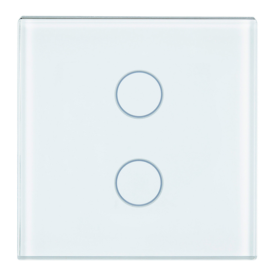
· Tastsensor 2-fach: bestehend aus Grundmodul 2-fach (Bild 4)
und einer Abdeckung 2-fach (Bild 3), jeweils in der Farbe weiß
oder schwarz. Die Abdeckung besitzt vier Tastflächen.
· Tastsensor 4-fach: bestehend aus Grundmodul 4-fach (Bild 6)
und einer Abdeckung 4-fach (Bild 5), jeweils in der Farbe weiß
oder schwarz. Die Abdeckung besitzt acht Tastflächen.
Die Tastsensoren sind mit einem Annäherungssensor ausgestat-
tet.
Die Tastsensoren, bestehend aus Tastsensor Abdeckung und Tast-
sensor Grundmodul, werden auf einen Busankoppler (BTM) auf-
gesteckt. Dabei wird die elektrische Verbindung zwischen dem
Tastsensor Grundmodul und dem Busankoppler (BTM) über das
Bus Transceiver Interface (BTI) hergestellt.
Die Tastsensor Abdeckung, das Tastsensor Grundmodul und der
Busankoppler (BTM) UP 117 werden jeweils einzeln bestellt (siehe
gültiger Katalog).
Tastsensor Grundmodul 1-
fach
5WG1 211-2DB01
Tastsensor Abdeckung 1-
fach
5WG1 211-8DB11
5WG1 211-8DB21
Touch Sensor Unit
single
5WG1 211-2DB01
Touch Sensor Cover
sin-
gle
5WG1 211-8DB11
5WG1 211-8DB21
D
Seite 1 von 4
Tastsensor Grundmodul 2-
fach
5WG1 212-2DB01
Tastsensor Abdeckung 2-
fach
5WG1 212-8DB11
5WG1 212-8DB21
Touch Sensor Unit
doub-
le
5WG1 212-2DB01
Touch Sensor Cover doub-
le
5WG1 212-8DB11
5WG1 212-8DB21
Product and Applications Description
The Touch Sensor Cover offers one, two, or four vertically ar-
ranged touch button pairs. They are each surrounded by transpa-
rent rings which are backlit by a status LED. The backlighting can
be set to seven different colors and also be used as orientation
lighting.
Each Touch Sensor consists of a sensor unit and a square sensor
cover.
The sensor unit includes the electronics with a programming but-
ton, a programmer LED and the Bus Transceiver Interface (BTI).
The cover is made of white or black glass. It contains the
respective buttons with the illuminated rings.
The touch sensors are available in the following designs:
· Touch sensor single: consisting of a single unit (Fig. 2) and a
single cover (Fig. 1), each in the color white or black. The cover
includes two buttons.
· Touch sensor double: consisting of a double unit (Fig. 4) and a
double cover (Fig. 3), each in the color white or black. The
cover includes four buttons.
· Touch sensor quadruple: consisting of a quadruple unit (Fig. 6)
and a quadruple cover (Fig. 5), each in the color white or
black. The cover includes eight buttons.
The touch sensors are equipped with a proximity sensor.
The touch sensors, consisting of a touch sensor cover and a touch
sensor unit, are attached to a bus coupling unit (BTM). In this
process, the electrical connection between the touch sensor unit
and the bus coupling unit (BTM) is made by the Bus Transceiver
Interface (BTI).
The touch sensor cover, the touch sensor unit and the bus
coupling unit (BTM) UP 117 are each ordered separately (see valid
catalog).
Tastsensor Grundmodul 4-
fach
5WG1 213-2DB01
Tastsensor Abdeckung 4-
fach
5WG1 213-8DB11
5WG1 213-8DB21
Touch Sensor Unit
quadruple
5WG1 213-2DB01
Touch Sensor Cover
quadruple
5WG1 213-8DB11
5WG1 213-8DB21
GB
page 1 of 4
Advertisement

Related Manuals for Siemens GAMMA instabus 5WG1 211-2DB01


Summary of Contents for Siemens GAMMA instabus 5WG1 211-2DB01
- Page 1 GAMMA instabus Tastsensor Glas Touch Sensor Glass Bedien- und Montageanleitung Operating and Mounting Instructions Stand: März 2015 Issued: March 2015 Produkt Tastsensor Grundmodul 1- Tastsensor Grundmodul 2- Tastsensor Grundmodul 4- fach fach fach 5WG1 211-2DB01 5WG1 212-2DB01 5WG1 213-2DB01 Produkt Tastsensor Abdeckung 1- Tastsensor Abdeckung 2- Tastsensor Abdeckung 4-...
- Page 2 Produkt- und Funktionsbeschreibung Product and Applications Description Gemeinsame Funktionen Common functions Tastflächen Touch Buttons Je nach Ausführung bietet der Tastsensor zwei bis acht Tastflä- Depending on the design, the touch sensor offers two to eight chen (Bild 7/8/9: A1, A2, B1, B2, C1, C2, D1, D2), die vertikal je- touch buttons (Fig.
- Page 3 All of the touch button pairs are pre-configured for the building Alle Tastflächenpaare sind mit der Baustellenfunktion für Schal- site function for switching (left on, right off). ten (oben Ein, unten Aus) vorbelegt. Additional Information Weitere Informationen http://www.siemens.com/gamma http://www.siemens.de/gamma Technical Specifications Technische Daten Power supply Spannungsversorgung ·...
- Page 4 · Any defective device must be sent back together with a return digen Vertriebsniederlassung zurückzusenden. http://support.automation.siemens.com delivery note from the local Siemens office. · Bei zusätzlichen Fragen zum Produkt wenden Sie sich bitte an · Please contact our Technical Support with any additional unseren Technical Support.
Need help?
Do you have a question about the GAMMA instabus 5WG1 211-2DB01 and is the answer not in the manual?
Questions and answers