Table of Contents
Advertisement
Quick Links
Advertisement
Table of Contents

Related Manuals for TDK-Lambda RWS-B Series


Summary of Contents for TDK-Lambda RWS-B Series
- Page 1 (217) 352-9330 | Click HERE Find the TDK-Lambda RWS600B-48 at our website:...
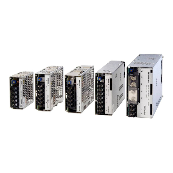
- Page 2 RWS-B SERIES Single output 50W - 600W ・ UNIT PC Board UL60950-1/ UL508/CSA C22.2 EN60950-1 CSA C22.2 No.107.1-01 No.60950-1 warranty ■ Features ■ Model naming method ● It is the simple function model who this product RWS 100 B - 24 / □ maintains basic performance, and planned the optimization of the addition function.
- Page 3 RWS50B Specifications (Read instruction manual carefully, before using the power supply unit.) ・ UNIT PC Board MODEL RWS50B-5 RWS50B-12 RWS50B-24 RWS50B-48 ITEM S/UNITS Input Voltage Range (*2)(*12) AC85 - 265 (47 - 63Hz) or DC120 - 370 Efficiency(100VAC) (typ) (*1) Efficiency(200VAC) (typ) (*1) Input...
-
Page 4: Outline Drawing
Outline Drawing ・ UNIT PC Board 【RWS50B】 2-M3 TAPPED HOLES (BACK SIDE) VOLTAGE ADJUSTMENT SCREW PENETRATION DEPTH MAX. 6mm 71±0.5 (11.7) 5-M3.5 NAME PLATE(1) NAME PLATE(2) (15.6) 81.5±1 34±1 2-M3 TAPPED HOLES SCREW PENETRATION DEPTH MAX. 6mm 20 MAX 48±0.5 [unit: mm] Output Derating ●... - Page 5 100B RWS100B Specifications (Read instruction manual carefully, before using the power supply unit.) ・ UNIT PC Board MODEL RWS100B-5 RWS100B-12 RWS100B-24 RWS100B-48 ITEM S/UNITS AC85 - 265 (47 - 63Hz) or DC120 - 370 Input Voltage Range (*2)(*11) Power factor (100/200VAC) (typ) (*1)(*11) 0.95/0.90 Efficiency(100VAC) (typ)
- Page 6 100B Outline Drawing ・ UNIT PC Board 【RWS100B】 95±0.5 VOLTAGE ADJUSTMENT ( 11.7 ) 5-M3.5 NAME PLATE(1) NAME PLATE(2) 2-M3 TAPPED HOLES (BACK SIDE) (15.6) 108±1 SCREW PENETRATION 39±1 DEPTH MAX. 6mm 2-M3 TAPPED HOLES SCREW PENETRATION DEPTH MAX. 6mm 20MAX 6.5 95±0.5 [unit: mm]...
- Page 7 150B RWS150B Specifications (Read instruction manual carefully, before using the power supply unit.) ・ UNIT PC Board MODEL RWS150B-5 RWS150B-12 RWS150B-24 RWS150B-48 ITEMS/UNITS AC85 - 265 (47 - 63Hz) or DC120 - 370 Input Voltage Range (*2)(*11) Power factor (100/200VAC) (typ) (*1)(*11) 0.95/0.90 Efficiency(100VAC) (typ)
- Page 8 150B Outline Drawing ・ UNIT PC Board 【RWS150B】 VOLTAGE 11.7 ) 118±0.5 ADJUSTMENT 5-M3.5 NAME PLATE(1) NAME PLATE(2) (15.6) 2-M3 TAPPED HOLES (BACK SIDE) 128±1 SCREW PENETRATION 41±1 DEPTH MAX. 6mm 2-M3 TAPPED HOLES SCREW PENETRATION DEPTH MAX. 6mm 20MAX 109±0.5 [unit: mm] Output Derating...
- Page 9 300B RWS300B Specifications (Read instruction manual carefully, before using the power supply unit.) ・ UNIT PC Board MODEL RWS300B-5 RWS300B-12 RWS300B-15 RWS300B-24 RWS300B-36 RWS300B-48 ITEM S/UNITS AC85 - 265 (47 - 63Hz) or DC120 - 370 Input Voltage Range (*2)(*11) Power factor (100/200VAC) (typ) (*1)(*11) 0.95/0.90...
- Page 10 300B Outline Drawing ・ UNIT PC Board 【RWS300B】 Air flow VOLTAGE ADJUSTMENT 157.5±0.5 (11.2) NAME PLATE(1) 7-M3.5 NAME PLATE(2) (15.1) 2-M3 TAPPED HOLES (BACK SIDE) 170±1 SCREW PENETRATION 41±1 DEPTH MAX. 6mm 2-M3 TAPPED HOLES SCREW PENETRATION DEPTH MAX. 6mm 20MAX 116±0.5 5MAX...
- Page 11 600B RWS600B Specifications (Read instruction manual carefully, before using the power supply unit.) ・ UNIT PC Board MODEL RWS600B-5 RWS600B-12 RWS600B-15 RWS600B-24 RWS600B-36 RWS600B-48 ITEM S/UNITS AC85 - 265 (47 - 63Hz) or DC120 - 330 Input Voltage Range (*2)(*11) Power factor (100/200VAC) (typ) (*1)(*11) 0.95/0.90...
- Page 12 600B Outline Drawing ・ UNIT PC Board 【RWS600B】 VOLTAGE Air flow ADJUSTMENT (18.6) 147±0.5 (11.2) 4-M5 NAME PLATE(1) NAME PLATE(2) 3-M3.5 2-M3 TAPPED HOLES (BACK SIDE) 140±0.5 (15.1) 5MAX SCREW PENETRATION DEPTH MAX. 6mm 190±1 2-M3 TAPPED HOLES SCREW PENETRATION DEPTH MAX.
-
Page 13: Block Diagram
Block Diagram ・ UNIT PC Board 【RWS50B】 Input Output 85 265VAC Inrush Current Limit Circuit Circuit Photo- Circuit Coupler Sensing Photo- Output Coupler Sensing Fuse rating 3.15A Circuit topology Switching frequency Flyback topology 100kHz 【RWS100B】 Input Output 85 265VAC Circuit Photo- Circuit Coupler... - Page 14 Block Diagram ・ UNIT PC Board 【RWS150B】 Input Output 85 265VAC Circuit Photo- Circuit Coupler Sensing Photo- Output Coupler Sensing Fuse rating 5A Circuit topology Switching frequency Single-ended forward topology 120kHz PFHC circuit : Active filter 65kHz (fixed) 【RWS300B, RWS300B/R】 Input Output 85 265VAC...
- Page 15 Block Diagram ・ UNIT PC Board 【RWS600B, RWS600B/R】 Input Output 85 265VAC Circuit Photo- Circuit Coupler Sensing Photo- Output Coupler Sensing Photo- Remote ON/OFF Coupler Control *Optional ”/R” 【RWS600B/FO, RWS600B/RFO】 Input Output 85 265VAC Circuit Photo- RWS-B Circuit Coupler Sensing Photo- Output Coupler...
-
Page 16: Sequence Time Chart
Sequence Time Chart ・ UNIT PC Board 【RWS50B-RWS150B】 Input Voltage OVP Point( 1) Vout ( 1) OVP Point 5V – 24V : 120% - 140% Output Voltage 48V : 115% - 135% 【RWS300B】 Input Voltage OVP Point( 1) Vout ( 1) OVP Point Output Voltage 5V –... - Page 17 TDK-Lambda. ● D o n o t o p e r a t e t h e s e p r o d u c t s i n t h e p r e s e n c e o f condensation.
- Page 18 RWS-B 1. Model name identification method ・ UNIT PC Board RWS 100 B - 24 / □ Output Power Rated Output type Voltage Option Series Name Blank: Standard With remote ON/OFF control model. (Option of RWS300B, RWS600B) /FO: With remote sensing Low output voltage (LV) signal Parallel Operation (Option of RWS600B)
- Page 19 RWS-B RWS600B ・ UNIT ⑥ PC Board ①N : Input terminal Neutral line (M3.5 screw) ⑦ ②L : Input terminal Live line (Fuse in line) (M3.5 screw) ⑧ ③ : Earth terminal ⑤ ④–V : –Output terminal (50A max. / terminal, M5 screw) ⑤+V : +Output terminal ④...
-
Page 20: Connecting Method
RWS-B 3. Connecting method ・ UNIT PC Board Pay attention to the input wiring. If it is connected to wrong terminal, the power supply will be damaged. ●Input must be off when making connections. ●Connect terminal to earth (frame ground of the equipment etc.) by thick wire for safety and improvement of noise sensitivity. RWS50B, RWS100B, RWS150B RWS300B RWS600B... - Page 21 RWS-B RWS600B/FO ・ UNIT PC Board ・ Basic connection (Local sensing) ・ Remote sensing connection Connect "+S" terminal (Pin No.2) to "+Vm" 1) Connect "+S" terminal (Pin No.2) to "+" output terminal (Pin No.1), and "-S" terminal (Pin No.10) to "-Vm" terminal of load with wires.
- Page 22 110VAC. adjustable. Never apply higher voltage externally to the output Note : RWS-B series is able to withstand input of 300VAC for 5 terminal to avoid unit failure. In case of inductive load, put seconds (No damage). Please note that to satisfy the electrical protective diode in se-ries to the output power line.
-
Page 23: Series Operation
RWS-B RWS600B/FO, RWS600B/RFO 4-7. Series Operation Operation to increase the Output Current is provided on option ・ UNIT PC Board model /FO and /RFO. For series operation, either method ( A ) or ( B ) is possible. By connecting +P terminal (Pin No.7) and -P terminal (Pin No.8), parallel operation is possible. -
Page 24: Withstand Voltage
RWS-B 4-9. Isolation Test 4-10. Withstand Voltage ・ UNIT PC Board This series is designed to withstand 3.0kVAC between input Isolation resistance between Output- terminal is more than 100MΩ at 500VDC. For safety operation, voltage setting of DC and output, 2.0kVAC between input and terminal and 500VAC isolation tester must be done before the test. - Page 25 RWS-B ■ Output- terminal : 500VAC, 1min (100mA) 4-11. Remote Sensing (+S, -S terminal) (RWS600B Option) ・ UNIT (A)RWS50B, RWS100B, RWS150B PC Board Remote Sensing function is provided on option model /FO and / AC(L) RFO. AC(N) This function compensates voltage drop of wiring from output –V terminals to load terminals.
- Page 26 4-13. Remote ON/OFF Control 4-15. Unadjustable trimmer (RWS300B, RWS600B Option) ・ UNIT PC Board Absolutely never adjust the trimmer shown below. It might cause power supply damage, if the trimmer is turned. Remote ON/OFF control function is provided on option model /R and /RFO.
-
Page 27: Mounting Method
RWS-B 5. Mounting Method ・ UNIT PC Board 5-2. Output Derating according to the 5-1. Mounting Method Mounting Directions RWS50B, RWS100B, RWS150B The standard mounting is direction ( A ). Direction ( B ), ( C ) (1) These models are convection cooling type power supply. and ( D ) are also possible. - Page 28 RWS-B ・ UNIT PC Board ・ RWS100B ・ RWS300B MOUNTING (A) MOUNTING (B), (C), (D) MOUNTING (A)-(D) –20 –10 –20 –10 Ta (°C) Ta (°C) Load (%) Load (%) Ta (℃ ) Ta (℃ ) Mounting (A) Mounting (B),(C),(D) Mounting (A)-(D) –20 –20 –10 to +35...
-
Page 29: Wiring Method
RWS-B 6. Wiring Method ・ UNIT PC Board (1) The output load line and input line shall be separated, and use all lines as thick and short as possible to make lower impedance. The output load line and input line shall be twisted or use shielded wire to improve noise (2) Remote sensing lines and remote ON/OFF control lines shall be twisted and separated from (3) Noise can be eliminated by attaching a capacitor to the load terminals. - Page 30 RWS-B 7. The life expectancy ・ UNIT PC Board The life expectancy of the power supply is as follows. ◇ RWS300B The life expectancy is dependent on the lifetime of electrolytic capacitor or the fan. Mounting(A),(B),(C),(D) The life expectancy is not a guaranteed value, please consider as a reference.
-
Page 31: Warranty Period
RWS-B 8. External Fuse Rating ・ UNIT PC Board Refer to the following fuse rating when selecting the external RWS50B, RWS100B: 3.15A input fuse. RWS150B: 5A Surge current flows when input turn on. Use slow-blow fuse or RWS300B: 10A time-lug fuse. Fast-blow fuse can not be used. RWS600B: 15A Fuse rating is specified by inrush current value at input turn on. - Page 32 RWS-B̲1403J a_RWS-B_31 Artisan Technology Group - Quality Instrumentation ... Guaranteed | (888) 88-SOURCE | www.artisantg.com...
- Page 33 *2. All included company names, products names and service marks, etc., are the trademarks or registered trademarks of TDK, TDK-Lambda or their subsidiaries in Japan and other countries. Note that the registered mark ® or TM are not used in this material, excluding one section.
Need help?
Do you have a question about the RWS-B Series and is the answer not in the manual?
Questions and answers