
Related Manuals for S&P REB 1


Summary of Contents for S&P REB 1
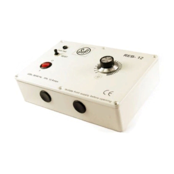
- Page 1 REB 1 REB 3 REB 5 REB 6 REB 8 REB 10 REB 12 REB 16 Manually Operated Electronic Speed Controller – Single Phase For all applications using suitably specified single-phase induction motor fans...
-
Page 2: Specification
4. The controller is housed in an enclosure that is suitable for the current rating and is IP42 rated. Table 1 Model Rated Current Fuse Size Number (Amps) REB 1 1 Amp 20mm ceramic 3.5 Amp “F” Type REB 3 3 Amps 20mm ceramic 5.0 Amp “F” Type REB 5 5 Amps 32mm ceramic 10.0 Amp “F”... -
Page 3: Installation
INSTALLATION 1. Check that the number, size and the speed of the fans can be safely controlled by this controller. 2. Install in a dry sheltered position. Leave an air space of not less than 150mm around the controller to allow cooling air to flow freely. Do not install in close proximity to other heat sources. - Page 4 Table 2 Electronic Wiring Speed Fan Model Diagram Controller REB 1 HCBB/4-250/H HCBB/4-315/H HCBB/6-355/H HCBB/6-400/H HCBB/4-355/H HCBB/4-400/H HCBB/4-450/H HCBB/6-450/H HCBB/6-500/H HCBB/6-560/H HXBR/4-400 HXBR/4-450 HXBR/6-400 HXBR/6-450 REB 3 HXBR/6-500 HXBR/6-560 HXBR/4-250 HXBR/4-315 HXBR/4-355 TXBR/4-315 TXBR/4-355 REB 5 HCBB/4-500/H HCBB/6-630/H HXBR/4-500 HXBR/6-630...
-
Page 5: Wiring Diagram
WIRING DIAGRAMS FOR ELECTRONIC SPEED CONTROLLERS (SINGLE PHASE 230V ~ 50Hz) L – Supply Live 230V 50Hz N – Supply Neutral U1 – Motor Control Variable Neutral U2 – Motor Live 230V ~ 50Hz A – Auxiliary Permanent Neutral E – Motor Supply Earth (E) WIRING DIAGRAM 1 WIRING DIAGRAM 2 WIRING DIAGRAM 3... - Page 6 WIRING DIAGRAM 6 – WIRING DIAGRAM 7a IMPORTANT NOTE FAN MOTOR HAS AN EMBEDDED THERMAL PROTECTION TRIP AND CASED-AXIAL AND IN-LINE FANS MUST BE WIRED VIA A MANUAL RESET THERMAL OVERLOAD FACILITY. WIRING DIAGRAM 8 – For use with “Other” S&P Fans where 3-wire control is NOT possible, the controller must be used as a 2-wire regulator.
-
Page 7: Troubleshooting
To reset push the reset button positioned near to the trip light. 16. IMPORTANT NOTE – REB 1, REB 3 and REB 5 only:- The controller does NOT have a thermal overload relay and as a consequence the common (U2 – motor live 230V) conductor is shown on the wiring diagrams routed via the thermal protector(s) in the fan(s) (terminals in the fan are designated TP). -
Page 8: Warranty Validation
24 (TWENTY FOUR) MONTH PRODUCT WARRANTY Soler and Palau Limited warrants that the REB 1, REB 3, REB 5, REB 6, REB 8, REB 10, REB 12 and REB 16 fan speed controllers will be free from defective materials and workmanship for the period of 24 (twenty four) months from the date of original purchase.