Table of Contents

Related Manuals for EDMI Atlas Series


Summary of Contents for EDMI Atlas Series
- Page 1 Atlas Series Energy Meters Mk10 / Mk7 Hardware Reference Manual Revision M Release Date: 2 September 2009 1910-E-02 EDMI Pty Ltd EDMI Limited 162 South Pine Rd Level 3 Brendale, Qld, 4500 No.47 Yishun Industrial Park A Australia Singapore 768724...
- Page 2 © Copyright 1999-2009, EDMI Pty Ltd. All rights reserved. Product names are trademarks or registered trademarks of their respective owners.
-
Page 3: Table Of Contents
TABLE OF CONTENTS Chapter 1 Introduction................1-1 Using this Manual ..........................1-1 Conventions Used in this Manual ...................... 1-1 For more information.......................... 1-2 Chapter 2 The Mk10 Meter................ 2-1 Dimensions and Mounting ......................... 2-1 External Features..........................2-4 Under the Terminal Cover........................2-5 Special I/O Variant ........................ - Page 4 RS-485 Passive........................... 5-14 RS-485 Active..........................5-14 FLAG Port..........................5-15 ANSI Port ........................... 5-15 Inputs ............................5-15 Outputs............................5-16 Battery............................5-16 LCD/Select Button..........................5-16 Connect / Boost Button........................5-17 Fitting a Modem ..........................5-18 Servicing ............................5-20 ii EDMI Atlas Hardware Reference Manual...
- Page 5 Chapter 6 The Mk10E Meter ..............6-1 Dimensions and Mounting ......................... 6-1 External Features..........................6-3 Under the Terminal Cover........................6-4 Terminal Block Variations ......................6-6 Terminal Cover Tamper Detect ....................6-6 Meter Lid Tamper Detect ......................6-6 Under the Meter Lid..........................6-7 CT to VT Links..........................
- Page 6 A-4 N ......................A-4 ABLE AMING CONVENTIONS LIST OF FIGURES • 2-1 O ..................2-1 IGURE VERALL DIMENSIONS OF THE METER • 2-2 M ..............2-2 IGURE OUNTING POINTS STANDARD TERMINAL COVER iv EDMI Atlas Hardware Reference Manual...
- Page 7 • 2-3 M ..............2-3 IGURE OUNTING POINTS EXTENDED TERMINAL COVER • 2-4 F ..........2-4 IGURE RONT VIEW OF THE METER WITH TERMINAL COVER FITTED • 2-5 U ............... 2-5 IGURE NDER THE TERMINAL COVER OF THE METER •...
- Page 8 • 7-6 E A LCD ..............7-4 IGURE XAMPLE OF FIRST PAGE OF DISPLAY • A-1 E ......................A-3 IGURE NERGY IRECTIONS • A-2 N ....................A-4 IGURE ONVENTION SETTINGS AMING vi EDMI Atlas Hardware Reference Manual...
-
Page 9: Chapter 1 Introduction
C h a p t e r Introduction C h a p t e r 1 This reference manual is for the EDMI Atlas series of Energy Meters. • Mk10 Three Phase Energy Meter (includes Mk10A) • Mk10D Three Phase Energy Meter with Disconnect •... -
Page 10: For More Information
EziView such as the scheduler, script files, and reading files. When contacting EDMI for support you may be asked for the meter serial number, firmware version and EziView version. The serial number is printed on the label, and is the serial number used in EziView to identify the meter. -
Page 11: Chapter 2 The Mk10 Meter
C h a p t e r The Mk10 Meter C h a p t e r 2 This chapter covers the basic installation and physical features of the Mk10 meter, including the UPS (Uninterruptable Power Supply), Special I/O and MK10A variants. Dimensions and Mounting Figure 2-1 shows the overall dimensions of the meter with a standard terminal cover. -
Page 12: Figure 2-2 Mounting Points, Standard Terminal Cover
Note that the dimension R4.75 is of the standoff, not of the hole. The lower mounting holes are oblong rather than round, to allow some adjustment in the meter position. The 76.18 mm dimension is to the centre of this hole. All dimensions are in mm. 2-2 EDMI Atlas Hardware Reference Manual... - Page 13 Dimensions and Mounting 76,18 76,18 5.70(2X) • Figure 2-3 Mounting points, extended terminal cover For mounting use three screws with a threaded section no larger than 5mm in diameter with a screw head no smaller than 8mm in diameter. In general: 1.
-
Page 14: External Features
The special I/O variant has 2 LED’s (PO1, PO2), the UPS variant has 1 LED (PO1) – in these variants the LED’s are independent of the outputs. • A FLAG or ANSI port for local connection. 2-4 EDMI Atlas Hardware Reference Manual... -
Page 15: Under The Terminal Cover
Under the Terminal Cover Beneath the terminal cover (accessible by removing the sealable screw on the top middle of terminal cover) is the terminal block for voltage and current, connectors for the pulsing inputs and outputs (optional), the optional RS-232 or RS-485 interface, and the optional external battery The sealable screws have 2.15mm diameter holes to accommodate standard sealing wire. -
Page 16: Special I/O Variant
This variant separates the LED’s from the I/O, and provides more I/O type options. Figure 2-7 shows the terminal layout, and Table 2-2 lists the terminal block connections. Battery Connector TB4 TB5 • Figure 2-7 Special I/O variant terminal block diagram 2-6 EDMI Atlas Hardware Reference Manual... -
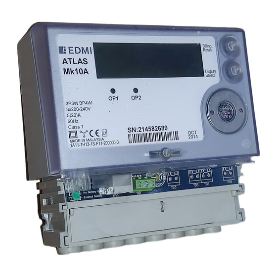
Page 17: Mk10A Variant
Under the Terminal Cover Terminal Description RJ45 connector which is hardware configured to either RS485 or RS232, or a 5 way terminal block for RS485. Voltage and current inputs. I/O - PI3 or PO3. I/O - PI4 or PO4. I/O - PI5 or PO5. I/O - PI6 or PO6. -
Page 18: Ups Variant
B a t t e r y C o n n e c t o r TB3 TB4 TB5 T B 6 J P 3 T B 2 • Figure 2-9 UPS variant terminal block diagram 2-8 EDMI Atlas Hardware Reference Manual... -
Page 19: Terminal Spacing
Under the Terminal Cover Terminal Description RJ45 connector which is hardware configured to either RS485 or RS232, or a 5 way terminal block for RS485. Voltage and current inputs. Active Input - PI3. Active Input - PI4. Active Input - PI5. UPS Battery connector. -
Page 20: New Terminal Block
Terminal Cover Tamper Detect The Mk10A meter has an optional switch that can detect the opening of the terminal cover. It is located above the battery connector. The meter can generate an EFA alarm 2-10 EDMI Atlas Hardware Reference Manual... -
Page 21: Meter Lid Tamper Detect
2-11 Under the Meter Lid and an event in the log when the switch is released by someone opening the terminal cover. Meter Lid Tamper Detect The Mk10A meter has an optional switch that can detect the opening of the meter lid. The meter can generate an EFA alarm and an event in the log when the switch is released by someone opening the meter lid. - Page 22 • Figure 2-15 Location of the CT to VT links To break the link the screws should be removed, leaving just the metal tab (Figure 2-16). 2-12 EDMI Atlas Hardware Reference Manual...
-
Page 23: Config Jumper
2-13 Under the Meter Lid • Figure 2-16 The removed screw and disconnected link Config Jumper The Config jumper offers a level of hardware security to the meter – the jumper needs to be fitted to allow calibration and recovery of lost passwords. The jumper is located under the meter lid, half way up the far left side of the circuit board (Figure 2-17). -
Page 24: Connections In Detail
TB2 terminals 1 to 2, 4 to 5, 8 to 9, and 12 to 13 to 14. The links are fitted under the main meter cover, discussed earlier in this chapter. The same maximum voltage restrictions apply as for CT meters. 2-14 EDMI Atlas Hardware Reference Manual... -
Page 25: Mk10 Serial Port Configurations
2-15 Connections in Detail Mk10 Serial Port Configurations The Mk10 meter has a number of single serial port options, listed in Table 2-6. Type Modem Communications None RS232 with RJ45 RS485 (4-wire) with RJ45 RS485 (4-wire) with Screw Terminals RS232 with RJ45 and GSM/GPRS Power Supply A-Band PLC C-Band PLC •... -
Page 26: Table 2-8 Rs-485 Connections
3 and 4 of PL8. PL8 is a 9 way jumper block located under the meter lid just behind TB1. Pin 1 is on the right hand side, near the PL8 label. Note that the 5-pin terminal block has a different pinout to the EDMI mk6 and mk3 meter RS485 ports. -
Page 27: Mk10A Serial Port Configurations
2-17 Connections in Detail Mk10A Serial Port Configurations The Mk10A meter has an option of one or two RS-232 ports, which can be arranged in a number of configurations with an RS485 port. The two ports are called Modem and SCADA. -
Page 28: Table 2-10 Mk10A Tb1 Connections
1 rather than pin 5 for RS485 options, which is different to many of the other EDMI meters – this allows better integration of the multiple ports. The connection on the label is indicated using a range of symbols that explain what the connections are. -
Page 29: Flag Port
The meter can have either Flag Port of ANSI Port. Standard Flag and ANSI read heads should work with the meter. Please note that older EDMI ANSI read heads will not work with the meter. To use a smart read head that can automatically switch polarity, set the DTR line to be low –... -
Page 30: Inputs
If an internal battery is used, a jumper will be connected to JP3 pin 1 and pin 2. To use an external battery, remove the jumper and plug the battery connector to pin 2 and 3 (polarized) of JP3. The external battery is clipped into the compartment to the right of 2-20 EDMI Atlas Hardware Reference Manual... -
Page 31: Ups Battery
LCD to be woken up. The UPS battery is a rechargeable 500mAh Ni-MH battery. It is a custom battery, replacements are available from EDMI. It connects to PL11, a small connector towards the right of the meter. -
Page 32: Lcd/Select Button
Servicing The meter is not designed for field servicing and has no user serviceable parts. The meter has no internal fuses. In the event of failure of the meter, contact EDMI or your local agent for servicing. 2-22 EDMI Atlas Hardware Reference Manual... -
Page 33: Chapter 3 The Mk10D Meter
C h a p t e r The Mk10D Meter C h a p t e r 3 This chapter covers the basic installation and physical features of the Mk10D meter. Dimensions and Mounting Figure 3-1 shows the overall dimensions of the meter with a standard terminal cover. The height excludes the buttons and the ANSI fitting if present. - Page 34 2. Hang the meter on the screw using the keyhole in the back of the meter. 3. Insert the remaining two screws (meter base, under the terminal cover) to hold the meter securely. 3-2 EDMI Atlas Hardware Reference Manual...
-
Page 35: External Features
External Features External Features Figure 3-3 shows a view of the front of the meter (the specifics of your label will vary). • Figure 3-3 Front view of the meter with terminal cover fitted The major parts visible in Figure 3-3 include: •... -
Page 36: Under The Terminal Cover
Most of the connections to the meter occur under the terminal cover. Figure 3-4 shows the terminals available on a 4 I/O / RS-232 meter. • Figure 3-4 Under the terminal cover of the meter Diagrammatically, this is shown in Figure 3-5 with the terminal block numbering. 3-4 EDMI Atlas Hardware Reference Manual... -
Page 37: Table 3-1 Terminal Block Connections
Under the Terminal Cover TB10 • Figure 3-5 Terminal block diagram Table 3-1 lists the terminal block connections. Terminal Description Voltage and current inputs. Input PI3 or Output PO3. Input PI4 or Output PO4. Input PI5 or Output PO5. Input PI6 or Output PO6. Second RJ45 connector for some communication options. -
Page 38: Terminal Block Variations
(See Figure 3-7). The meter can generate an EFA alarm and an event in the log when the switch is released by someone opening the terminal cover. • Figure 3-7 The terminal cover tamper detect button 3-6 EDMI Atlas Hardware Reference Manual... -
Page 39: Under The Meter Lid
Under the Meter Lid Under the Meter Lid Removing the sealable screw allows the meter lid to be removed. Generally connections to the I/O connectors do not need to be detached to allow the cover to be removed. Removal of the meter lid is required to access the Config Jumper, and to add or remove the CT to VT links on meters with old style terminal blocks. -
Page 40: Config Jumper
LCD (Figure 3-13). A jumper is fitted across the set of pins marked Config. The other set of pins marked FTest are for factory use only. • Figure 3-13 Location of the Config jumper 3-8 EDMI Atlas Hardware Reference Manual... -
Page 41: Connections In Detail
Connections in Detail Connections in Detail Current and Voltage • Figure 3-14 Connections for 3 element whole current Figure 3-14 shows the normal connections for a whole current meter (the meter is only available in a whole current configuration). The neutral connection must be made, even if it is not connected to both 12 and 14. -
Page 42: Serial Port Configurations
Type 7 port. There is only one RJ45 (TB10), it is a dual connector (2 serial ports on the one connector), power is supplied ( ), and both ports are RS232 (the top port is the Modem port, the bottom is the SCADA port). 3-10 EDMI Atlas Hardware Reference Manual... -
Page 43: Table 3-3 Rs-232 Connections
• Table 3-3 RS-232 connections * TB10-1 is connected to a +7V power source from the meter, which is designed to power an external GSM modem. Other options are also available, contact EDMI for more details. See Figure 3-4 and Figure 3-5 for the location of the RJ45 connector. It is designated as TB10. -
Page 44: Plc
To operate the meter in two wire mode, simply wire TX- to RX- and TX+ to RX+. These may be wired together as a factory fitted option. Note that the 5-pin terminal block has a different pinout to the EDMI mk6 and mk3 meter RS485 ports. -
Page 45: Ansi Port
The meter can have either Flag Port of ANSI Port. Standard Flag and ANSI read heads should work with the meter. Please note that older EDMI ANSI read heads will not work with the meter. To use a smart read head that can automatically switch polarity, set the DTR line to be low –... -
Page 46: Lcd/Select Button
The display may also be setup to automatically cycle the display through the pages, pausing if the Select button is pressed. For more detailed information on the LCD and Select button see Chapter 7: “LCD Display”. 3-14 EDMI Atlas Hardware Reference Manual... -
Page 47: Reconnect/Boost/Billing Reset Button
Servicing The meter is not designed for field servicing and has no user serviceable parts. The meter has no internal fuses. In the event of failure of the meter, contact EDMI or your local agent for servicing. The Mk10D Meter 3-15... - Page 48 3-16 Intentionally Left Blank 3-16 EDMI Atlas Hardware Reference Manual...
-
Page 49: Chapter 4 The Mk7A Meter
C h a p t e r The Mk7A Meter C h a p t e r 4 This chapter covers the basic installation and physical features of the Mk7A meter. Dimensions and Mounting Figure 4-1 shows the overall dimensions of the meter with a standard terminal cover. Height Depth Width... - Page 50 Figure 4-2 below gives more detailed dimensions for the meter. • Figure 4-2 Dimensions 4-2 EDMI Atlas Hardware Reference Manual...
- Page 51 Dimensions and Mounting For mounting use 3 screws with a threaded section no larger than 5mm in diameter with a screw head no smaller than 8mm in diameter. • Figure 4-3 Mounting points The meter is mounted using three screws as shown in Figure 4-3. In general: 1.
-
Page 52: External Features
• Two pulsing LEDs for energy indication (PO3 and PO4). • A FLAG or ANSI port for local connection. There is space for an optional Connect, Boost or Billing Reset button above the select button (See page 4-14). 4-4 EDMI Atlas Hardware Reference Manual... -
Page 53: Under The Terminal Cover
Under the Terminal Cover Beneath the terminal cover (accessible by removing the sealable screw on the top middle of the terminal cover) is the terminal block for the supply and loads, connectors for the pulsing inputs and outputs (optional), the optional RS-232 or RS-485 interface, and the optional external battery The sealable screws have 2.15mm diameter holes to accommodate standard sealing wire. -
Page 54: Table 4-1 Terminal Block Connections
Input PI6 & PI6 SØ Output or 240V/110V/48V/12V/5V Input or Active Input or 2A,240V Relay or BOSFET output TB6-1 Input /Output PI6 or PO6 TB6-2 Common for Input/Output #6 • Table 4-1 Terminal block connections 4-6 EDMI Atlas Hardware Reference Manual... -
Page 55: Finger Guard
Under the Terminal Cover The isolation between TB1 and TB2 is minimal. There is also minimal isolation between TB3 and TB6. The isolation between these groups and line (neutral) and TB4 is 4kV. Figure 4-7 gives the terminal spacing of TB5. •... -
Page 56: Terminal Cover Tamper Detect
(Figure 4-10). A jumper is fitted across the bottom set of pins marked JP1 Config. The top set of pins marked JP2 FTest are for factory use only. 4-8 EDMI Atlas Hardware Reference Manual... -
Page 57: Connections In Detail
Connections in Detail • Figure 4-10 Location of the Config jumper Connections in Detail Current and Voltage • Figure 4-11 TB5 Connections including a switched/metered load Figure 2-18 shows the connection method with an extra load circuit L2. The nominal voltage input range is 220 - 240 VAC. -
Page 58: Table 4-3 Configuration Options
Main. The secondary element I is referred to as Load. The third element measures the Neutral Current, and is referred to as Neutral. Total is the sum of Main and Load. 4-10 EDMI Atlas Hardware Reference Manual... -
Page 59: Flag Port
• Table 4-4 RS-232 connections * TB4-1 is connected to a +15V power source from the meter, which is designed to power an external GSM modem. Other options are also available, contact EDMI for more details. It may vary up to 20V with loading. -
Page 60: Ansi Port
The meter can have either Flag Port of ANSI Port. Standard Flag and ANSI read heads should work with the meter. Please note that older EDMI ANSI read heads will not work with the meter. For smart read heads that can automatically switch polarity, set the DTR line to be low –... -
Page 61: Lcd/Select Button
The external battery is clipped into the compartment above PL3. Replacement batteries may be ordered from EDMI separately. A low battery indicator is displayed on the LCD if the battery is not present or is depleted – the level this occurs at can be configured. -
Page 62: Reconnect/Boost Or Billing Reset Button
Pushing both the Select button and the Reconnect button at the same time will cause the contactor to be disconnected. The message “Disconnect” will be displayed on the LCD. The Reconnect button can also cause a boost operation for load control outputs, depending on configuration. 4-14 EDMI Atlas Hardware Reference Manual... -
Page 63: Servicing
Servicing The meter is not designed for field servicing and has no user serviceable parts. The meter has no internal fuses. In the event of failure of the meter, contact EDMI or your local agent for servicing. The Mk7A Meter 4-15... - Page 64 4-16 Intentionally Left Blank 4-16 EDMI Atlas Hardware Reference Manual...
-
Page 65: Chapter 5 The Mk7C Meter
C h a p t e r The Mk7C Meter C h a p t e r 5 This chapter covers the basic installation and physical features of the Mk7C meter. Dimensions and Mounting Figure 5-1 shows the overall dimensions of the meter with a standard terminal cover. Width Depth Height... - Page 66 Figure 5-2 below gives more detailed dimensions for the meter. Figure 5-3 gives the dimensions of the meter with a modem terminal cover fitted, which can house a GSM modem. • Figure 5-2 Dimensions with standard terminal cover • Figure 5-3 Dimensions with modem terminal cover 5-2 EDMI Atlas Hardware Reference Manual...
- Page 67 Dimensions and Mounting For mounting use 3 screws with a threaded section no larger than 5mm in diameter with a screw head no smaller than 8mm in diameter. • Figure 5-4 Mounting points The meter is mounted using three screws as shown in Figure 5-4. In general: 4.
-
Page 68: Hanging Extension
The clip can be easily removed with access to the back of the meter by pushing the centre part in and sliding the clip out. • Figure 5-5 The hanger extension clip • Figure 5-6 Hanging keyhole with the clip fitted 5-4 EDMI Atlas Hardware Reference Manual... -
Page 69: External Features
External Features External Features Figure 5-7 shows a view of the front of the meter (the specifics of your label will vary). • Figure 5-7 Front view of the meter with terminal cover fitted The major parts visible in Figure 5-7 include: •... -
Page 70: Under The Terminal Cover
PLC. This has an internal PLC communications interface, but no RS232 or RS485 port. • Table 5-1 Meter options Figure 5-9 illustrates the terminal layout diagrammatically, and Figure 5-10 gives the details of the terminal itself. 5-6 EDMI Atlas Hardware Reference Manual... - Page 71 Under the Terminal Cover • Figure 5-9 Terminal block diagram • Figure 5-10 TB1 terminal details Table 5-2 to Table 5-7 list the terminal block connections for the various configurations. All terminals numbered left to right. Terminal Description Voltage and current inputs. TB1-1 Incoming Active TB1-2...
-
Page 72: Table 5-3 Terminal Block Connections - Passive
RS485 – RJ45 4 wire RS485 – 2 way terminal block TB3-1 TX+/RX+ TB3-2 TX-/RX- TB4-1 240V, 2A Relay output TB4-2 Common for PO6 • Table 5-5 Terminal block connections - Active with relay 5-8 EDMI Atlas Hardware Reference Manual... -
Page 73: Finger Guard
Under the Terminal Cover Terminal Description TB2-1 PI1/PO1 SØ Output or 240V/110V/48V/12V/5V Input TB2-2 PI1/PO1 SØ Output or 240V/110V/48V/12V/5V Input TB2-3 Common for PI1/PO1 and PI2/PO2 TB3-1 PI5/PO5 SØ Output or 240V/110V/48V/12V/5V Input TB3-2 PI6/PO6 SØ Output or 240V/110V/48V/12V/5V Input TB3-3 Common for PI5/PO5 and PI6/PO6 Nothing Fitted... -
Page 74: Terminal Cover Tamper Detect
The Config jumper offers a level of hardware security to the meter – the jumper needs to be fitted to allow calibration and recovery of lost passwords. In the Mk7C the jumper is not permanently fitted. A connection must be made on the circuit board to enable the 5-10 EDMI Atlas Hardware Reference Manual... -
Page 75: Connections In Detail
5-11 Connections in Detail Config mode. The connection location is under the meter lid, in the middle near the top of the meter (Figure 5-13). A connection must be made between the two indicated circuit board pads for at least 1 second. This can be done while the meter is on, but is not recommended due to the difficulty in accessing it safely. -
Page 76: Passive
The meter draws power from the CD and/or CTS lines, so a least one of these lines should be always driven high by the modem. The meter does not sense the state of the CD line. 5-12 EDMI Atlas Hardware Reference Manual... -
Page 77: Active
5-13 Connections in Detail A minimal modem connection is thus GND, RX, TX, and either CD, or RTS and CTS. Connecting RTS/CTS can help with modems that have hardware flow control turned on by default. Preferably both CD and RTS/CTS should be connected. See Figure 5-8 and Figure 5-9 for the location of the RJ45 connector. -
Page 78: Passive
TB3-3 TB3-1 TX+ (A) Transmit + TB3-4 Ground TB3-5* +12V,200mA output TB3-6 TB3-2 TX- (B) Transmit Data TB3-7 TB3-2 RX- (B) Receive - TB3-8 TB3-1 RX+ (A) Receive + • Table 5-11 RS-485 connections 5-14 EDMI Atlas Hardware Reference Manual... -
Page 79: Flag Port
The meter can have either Flag Port of ANSI Port. Standard Flag and ANSI read heads should work with the meter. Please note that older EDMI ANSI read heads will not work with the meter. To use smart read heads that can automatically switch polarity, set the DTR line to be low –... -
Page 80: Outputs
A and B, battery indicator, currency indicator, connection type indicator for connection through local or remote port and units and multipliers. The LCD does not have a backlight • Figure 5-16 LCD with all segments turned on 5-16 EDMI Atlas Hardware Reference Manual... -
Page 81: Connect / Boost Button
5-17 Connect / Boost Button To progress to the next page, press the Select button. Each time the button is pressed the display moves to the next page. The display may also be setup to automatically cycle the display through the pages, pausing if the Select button is pressed. For more detailed information on the LCD and Select button see Chapter 7: “LCD Display”. -
Page 82: Fitting A Modem
The modem shown in Figure 5-19 is an ETM9300 GSM/GPRS modem from ETM Pacific. • Figure 5-19 An ETM9300 modem fitted to the meter 5-18 EDMI Atlas Hardware Reference Manual... - Page 83 5-19 Fitting a Modem The SAM2 GSM/GPRS modem from InterCEL is also supported, as shown in Figure 5-20. The modem is connected to the meter via a short cable, which plugs directly into the meters RJ45 modem port, and also supplies power to the modem. •...
-
Page 84: Servicing
Servicing The meter is not designed for field servicing and has no user serviceable parts. The meter has no internal fuses. In the event of failure of the meter, contact EDMI or your local agent for servicing. 5-20 EDMI Atlas Hardware Reference Manual... -
Page 85: Chapter 6 The Mk10E Meter
C h a p t e r The Mk10E Meter C h a p t e r 6 This chapter covers the basic installation and physical features of the Mk10E meter. Dimensions and Mounting Figure 6-1 shows the overall dimensions of the meter with a standard terminal cover. The height excludes the buttons and the ANSI fitting if present. - Page 86 4. Screw the first (top) screw into the wall. Leave enough space between the head and the wall for the plastic around the keyhole. 5. Hang the meter on the screw using the keyhole in the back of the meter. 6-2 EDMI Atlas Hardware Reference Manual...
-
Page 87: External Features
External Features 6. Insert the remaining two screws (meter base, under the terminal cover) to hold the meter securely. External Features Figure 6-3 shows a view of the front of the meter (the specifics of your label will vary). • Figure 6-3 Front view of the meter with terminal cover fitted The major parts visible in Figure 3-3 include: •... -
Page 88: Under The Terminal Cover
Most of the connections to the meter occur under the terminal cover. Figure 6-4 shows the terminals available on a 4 I/O / RS-232 meter. • Figure 6-4 Under the terminal cover of the meter Diagrammatically, this is shown in Figure 6-5 with the terminal block numbering. 6-4 EDMI Atlas Hardware Reference Manual... -
Page 89: Table 6-1 Terminal Block Connections
Under the Terminal Cover TB10 • Figure 6-5 Terminal block diagram Table 6-1 lists the terminal block connections. Terminal Description Voltage and current inputs. Input PI3 or Output PO3. Input PI4 or Output PO4. Input PI5 or Output PO5. Input PI6 or Output PO6. Second RJ45 connector for some communication options. -
Page 90: Terminal Block Variations
The meter has an optional switch that can detect the opening of the meter lid. The meter can generate an EFA alarm and an event in the log when the switch is released by someone opening the meter lid. 6-6 EDMI Atlas Hardware Reference Manual... -
Page 91: Under The Meter Lid
Under the Meter Lid Under the Meter Lid Removing the sealable screw allows the meter lid to be removed. Generally connections to the I/O connectors do not need to be detached to allow the cover to be removed. Removal of the meter lid is required to access the Config Jumper, and to add or remove the CT to VT links on meters with old style terminal blocks. -
Page 92: Config Jumper
LCD (Figure 6-13). A jumper is fitted across the set of pins marked Config. The other set of pins marked FTest are for factory use only. • Figure 6-13 Location of the Config jumper 6-8 EDMI Atlas Hardware Reference Manual... -
Page 93: Connections In Detail
Connections in Detail Connections in Detail Current and Voltage • Figure 6-14 TB1 CT and VT connections for 3 element (top) and 2 element (bottom). Figure 6-14 shows the two possible connection methods in either 2 (3 wire) or 3 (4 wire) element mode. - Page 94 • Figure 6-16 TB1 CT and VT connections for 3 element testing Figure 6-16 shows the connection methods in 3 element (4 wire) mode when VT/CT links are not fitted. 6-10 EDMI Atlas Hardware Reference Manual...
-
Page 95: Serial Port Configurations
6-11 Connections in Detail Serial Port Configurations The meter has an option of one or two RS-232 ports, which can be arranged in a number of configurations with an RS485 port. The two ports are called Modem and SCADA. The possible options are listed in Table 6-2, which lines up with the order code options. Type Modem Communications None... -
Page 96: Table 6-3 Rs-232 Connections
* TB10-1 is connected to a +14V power source from the meter, which is designed to power an external GSM modem. Other options are also available, contact EDMI for more details. Some early meters may have been built with a 2W limit – check with EDMI if you have a concern. -
Page 97: Flag Port
To operate the meter in two wire mode, simply wire TX- to RX- and TX+ to RX+. These may be wired together as a factory fitted option. Note that the 5-pin terminal block has a different pinout to the EDMI mk6 and mk3 meter RS485 ports. -
Page 98: Inputs
– the level this occurs at can be configured. The battery usage life is longer than 10 years on continuous backup with either of the 700mAh batteries at 25°C. In normal operation the battery should last for more than 10 years. 6-14 EDMI Atlas Hardware Reference Manual... -
Page 99: Super Cap
6-15 Super Cap To eliminate the possibility of data loss it is best to change the battery while the meter is running. Care must be taken as the battery is at the potential of the neutral terminal. The battery is at the potential of the neutral terminal. If conditions (such as wiring configuration) make this a dangerous operation then steps should be taken to ensure that it is safe to do so. -
Page 100: Reconnect/Boost/Billing Reset Button
Servicing The meter is not designed for field servicing and has no user serviceable parts. The meter has no internal fuses. In the event of failure of the meter, contact EDMI or your local agent for servicing. 6-16 EDMI Atlas Hardware Reference Manual... -
Page 101: Chapter 7 Lcd Display
C h a p t e r LCD Display C h a p t e r 7 The LCD is primarily for displaying information from the meter’s registers for meter readers. It is also useful during installation, configuration, and diagnosing problems. It has 8 seven-segment digits to display values and up to 7 seven-segment digits to display description. - Page 102 It adds a currency symbol and a SCADA port symbol, but drops the G and M multipliers, and limits the decimal places to 4. • Figure 7-4 Mk10A LCD with all segments turned on 7-2 EDMI Atlas Hardware Reference Manual...
-
Page 103: Lcd/Select Button Usage
LCD/Select Button Usage The Mk7 LCD is very similar to the Mk10, but has fewer features and is physically smaller (Figure 7-5). There are 4 label digits, and 5 enunciators. • Figure 7-5 Mk7 LCD with all segments turned on LCD/Select Button Usage The data is displayed on the LCD as a series of pages, up to a maximum of 90. -
Page 104: Display Sets
In general, the organisation of the display from the top left is as follows (Table 7-1): The four arrows with characters and plus/minus sign at the top left display the direction of Watts and vars respectively. A plus sign indicates positive/export/delivered energy, while a minus sign indicates negative/import/received 7-4 EDMI Atlas Hardware Reference Manual... -
Page 105: Table 7-1 Sections Of The Lcd
Display Organisation energy The three characters show presence of phase voltage. L1 represents phase A voltage, L2 represents phase B voltage and L3 represents phase C voltage. Not present on Mk7. Low Battery indicator. Please refer to the section on the battery earlier this chapter. - Page 106 As the LCD is a numeric type, alphabetic characters are difficult to display. The meter will attempt to display them as best it can, but readability will vary depending on the letter. 7-6 EDMI Atlas Hardware Reference Manual...
-
Page 107: Appendix A System Specifications
A p p e n d i x S ystem Specifications A p p e n d i x A This appendix covers the basic specifications of the meter. Measured Quantities and Methods The meter can measure the quantities listed in Table A-1. Quantity Units Description... -
Page 108: Operating Conditions
Damp Heat Cyclic Test +60°C (IEC is 40°C) Indoor, Australian Outdoor. Mk7C Outdoor. Location Non-condensing: Annual mean <75%, 30 days 95% (in a natural Relative Humidity spread), occasionally 85% • Table A-2 Operating Conditions A-2 EDMI Atlas Hardware Reference Manual... -
Page 109: Energy Conventions
Energy Conventions Quantity Conditions Electromagnetic Environment E2, per the 2004/22/EC directive EMC Environment (Pending for Mk10E, Mk10A) Insulation Protective class II Surge Test 5kV (IEC is 4kV) Impulse Test 12kV (IEC is 6kV) Mk10, Mk10E 10kV (IEC is 6kV) Mk10D, Mk10A, Mk7A, Mk7C 12kV, Ri = 40Ω... -
Page 110: Table A-4 Naming Conventions
The naming conventions are as in Table A-4. Standard Positive Negative Abbreviated Energy Energy ANSI Export Import Exp/Imp Import Export Imp/Exp Rec/Del Delivered Received Del/Rec Fwd/Rev Forward Reverse Fwd/Rev • Table A-4 Naming conventions A-4 EDMI Atlas Hardware Reference Manual...
Need help?
Do you have a question about the Atlas Series and is the answer not in the manual?
Questions and answers
I have EDMI MK7A , PLEASE PROVIDE ME THE SYMBOLS NEEDED IN READING MY METER.
To read the EDMI MK7A meter, the following symbols and indicators are used:
- L: Indicates local communication or login on the local port.
- R: Indicates remote communication or login on the modem port. It flashes if connected to the GPRS network in persistent mode with no active login.
- Currency indicator: Present on Mk7 and Mk10A only.
- GMk: Multiplier symbols, where G = Giga, M = Mega, k = kilo. Only "k" is available on Mk7.
- Units: The display can show units such as W, var, VA, Wh, varh, VAh, V, and A.
- Label: Up to 4 seven-segment characters on Mk7 to describe the displayed value.
These symbols help identify the type of data shown on the LCD display.
This answer is automatically generated
What is the terminal size for 6 mmcopper core terminal
DO I NEED A SWITCH DIN DROPLET WITH MY SMART METER ACUMEN EDMI ATLAS MK7A S/N 216500355