
Related Manuals for PEKO SD-1700


Summary of Contents for PEKO SD-1700
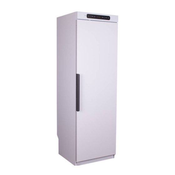
- Page 1 Drying Cabinet Drying Cabinet Installation and Operating Manual Installation and Operating Manual Model:- SD-1700 SD-1900 Electronic Sensor Drying...
-
Page 2: Table Of Contents
DIMENSION DRAWING START UP Peko Equipment Limited UK Distributor: PEKO Equipment Limited reserve the right to make improvements and/ or changes to the Unit 3, Bourne End Mills cabinet and to the contents of this manual. Upper Bourne End Lane... -
Page 3: This User Manual
NOTE. Keep this user The contents of this user manual describes the functions of manual so it is always the SD-1700 / 1900 drying cabinet and how it should be used. available for future use. It also includes instructions for installation and maintenance. -
Page 4: Description Of The Cabinet
DESCRIPTION OF THE CABINET Models SD-1700 / 1900: Supplied with an electronic controller with automatic senor drying and manual timer control options. Three hanging rail sections are fitted equivalent to 16m length of washing line space. Each section can slide outwards to assist the loading process. The middle and lower sections are hinged so that when pushed back into the cabinet they can be folded back to allow longer garments to hang freely from the upper set of rails. -
Page 5: Installation
INSTALLATION UNPACKING THE CABINET The cabinet must be handled After unpacking, check that the product is free of carefully at all times. faults. Damage, defects and any missing parts must be immediately reported to the dealer. RISK OF TIPPING OVER. Check that all transportation securing devices have been removed before connecting the dryer. -
Page 6: Door Adjustment
INSTALLATION DOOR ADJUSTMENT Minor adjustments to the door can be made by small alterations to the front levelling feet after the cabinet has been secured. RESTORING THE DOOR SEALING GASKET Initially the door gasket may be slightly squashed as a result of the packaging process. This will normally restore to full flexibility with the application of the heat generated by the drying cabinet. -
Page 7: Location And Fixing
INSTALLATION LOCATION AND FIXING The drying cabinet should not be installed in The drying cabinet should not be installed in a a location where high pressure water is used location where any doorways or safety exits are for cleaning. blocked when the door is open and the hanging rails extended. -
Page 8: Electrical Connection
INSTALLATION ELECTRICAL CONNECTION The cabinet is supplied ready for connection to the power supply with a UK style 3-pin plug complete with a 10 A fuse. Power supply rated at 230 V single-phase 50 Hz. The power cable is approx. 1.9 m in length. The plug (and socket outlet) should be in an accessible position for ease of removal. -
Page 9: Ventilation Connection
INSTALLATION VENTILATION / EXTRACTION SYSTEMS NOTE. The exhaust ducting should not be connected into an existing chimney, boiler flue or tumble dryer system. To prevent the build-up of heat and moisture within the room, it is recommended that a ventilation system is connected to the cabinet. -
Page 10: Additional Ventilation Notes
INSTALLATION ADDITIONAL GUIDANCE NOTES FOR VENTILATION DUCTING SYSTEMS Notes: · Standard tumble dryer back draught shutters are not suitable. Permanently open louvre or cowl fit- tings with insect mesh screen should be used. · The maximum effective length of ducting to outside is 3m. Keep the ducting length as short as pos- sible with the minimum number of bends for maximum efficiency. -
Page 11: Start Up
To avoid any potential transfer of colours, keep light and dark/ coloured materials separate. This figure shows The SD-1700 / 1900 cabinet contains three sets of how the air flows hanging rails. Each set has 11 bars on which to within the cabinet. -
Page 12: Control Panel
CONTROL PANEL The drying cabinet is equipped with both automatic and manual time controls. DRYING PROGRAMMES - AUTOMATIC TIME CONTROL To start up automatic time control: The cabinet is started by pressing the ON/OFF button. By default, the cabinet will be activated with the previous programme selection. If no programme has been selected previously, the cabinet has been without power or is completely new, the cabinet is started in AUTO HIGH by default. -
Page 13: Manual Time Control
DRYING PROGRAMMES - AUTOMATIC TIME CONTROL You can also select additional functions: EXTRA DRY can be used when either AUTO LOW or AUTO HIGH is selected. EXTRA DRY is for fabrics that are thicker and more difficult to dry such as overalls. ski suits, etc. -
Page 14: Adjusting The Drying Programmes
ADJUSTING THE DRYING PROGRAMMES The drying cabinet’s automatic programmes can be optimised in relation to the existing installation conditions. This is done by adjusting the parameter values for the automatic programme concerned on the control panel. This is only to be done if you find that: The washing is not dried sufficiently or, The washing is over-dried. -
Page 15: Service And Replacement Parts
CARE SERVICE AND REPLACEMENTS PARTS You MUST first disconnect the cabinet from If the connecting cable is damaged for any the power source, then open the door before reason, it must be replaced immediately. removing the five screws underneath the control All genuine parts can be obtained from the drying panel. -
Page 16: Troubleshooting
TROUBLESHOOTING Problem What you can do The fan does not operate and Check that the cabinet is connected to the power supply and that the cabinet is not heating up: the fuses are intact. When the cabinet is switched on, there should be a time displayed from the previous drying programme and two LEDs should be lit. -
Page 17: Technical Data
The electrical wiring diagram and dimension drawing can be obtained from the distributor (see contact details on page 2 of this manual). They can also be found under the ‘Downloads’ section of the Peko Drying Cabinet website; www.pekodryingcabinets.co.uk. Installation and Operating Manual Page 17... -
Page 18: Dimension Drawing
DIMENSION DRAWING Installation and Operating Manual Page 18... - Page 19 Installation and Operating Manual Page 19...
- Page 20 EQUIPMENT LIMITED Unit 3, Bourne End Mills Upper Bourne End Lane Hemel Hempstead Herts. HP1 2UJ Tel: 01442 872323 info@peko.co.uk www.pekodryingcabinets.co.uk...
Need help?
Do you have a question about the SD-1700 and is the answer not in the manual?
Questions and answers