Sign In
Upload
Manuals
Brands
Infineon Manuals
Microcontrollers
XC800 Series
Infineon XC800 Series Manuals
Manuals and User Guides for Infineon XC800 Series. We have
4
Infineon XC800 Series manuals available for free PDF download: User Manual, Using Manual, Manual, Application Note
Infineon XC800 Series User Manual (461 pages)
8-Bit Single Chip Microcontroller
Brand:
Infineon
| Category:
Microcontrollers
| Size: 5.37 MB
Table of Contents
Table of Contents
5
1 Introduction
13
Feature Summary
17
Pin Configuration
19
Pin Definitions and Functions
20
Textual Convention
26
Reserved, Undefined and Unimplemented Terminology
27
Acronyms
28
2 Processor Architecture
29
Functional Description
30
CPU Register Description
32
Stack Pointer (SP)
32
Data Pointer (DPTR)
32
Accumulator (ACC)
32
B Register
32
Program Status Word
33
Extended Operation Register (EO)
34
Power Control Register (PCON)
35
Instruction Timing
36
3 Memory Organization
43
Program Memory
45
Data Memory
45
Internal Data Memory
45
External Data Memory
45
Memory Protection Strategy
47
Memory Protection
47
Flash Protection Enable
49
Special Function Registers
51
Address Extension by Mapping
51
Address Extension by Paging
54
Bit-Addressing
57
System Control Registers
58
Bit Protection Scheme
60
XC866 Register Overview
61
CPU Registers
61
System Control Registers
62
WDT Registers
64
Port Registers
64
ADC Registers
65
Timer 2 Registers
68
CCU6 Registers
68
SSC Registers
72
OCDS Registers
73
Boot ROM Operating Mode
74
User Mode
74
Bootstrap Loader Mode
74
OCDS Mode
74
User JTAG Mode
74
4 Flash Memory
75
Flash Memory Map
76
Flash Bank Sectorization
77
Wordline Address
79
Operating Modes
81
Error Detection and Correction
83
In-System Programming
84
In-Application Programming
85
Flash Programming
85
Flash Erasing
88
Aborting Flash Erase
91
Flash Bank Read Status
92
5 Interrupt System
93
Interrupt Structure 1
99
Interrupt Structure 2
100
Interrupt Source and Vector
102
Interrupt Register Description
104
Interrupt Node Enable Registers
104
External Interrupt Control Registers
107
Interrupt Flag Registers
111
Interrupt Priority Registers
116
Interrupt Flag Overview
119
Interrupt Handling
120
Interrupt Response Time
121
6 Parallel Ports
124
General Port Operation
125
General Register Description
128
Data Register
129
Direction Register
130
Open Drain Control Register
131
Pull-Up/Pull-Down Device Register
132
Register Map
135
Port 0
138
Functions
138
Register Description
141
Port 1
144
Functions
144
Register Description
146
Port 2
149
Functions
149
Register Description
152
Port 3
154
Functions
154
Register Description
157
7 Power Supply, Reset and Clock Management
160
Power Supply System with Embedded Voltage Regulator
160
Reset Control
162
Types of Resets
162
Power-On Reset
162
Hardware Reset
164
Watchdog Timer Reset
164
Power-Down Wake-Up Reset
164
Brownout Reset
165
Module Reset Behavior
166
Booting Scheme
166
Register Description
167
Clock System
169
Clock Generation Unit
169
Functional Description
170
Clock Source Control
172
Clock Management
173
Register Description
175
8 Power Saving Modes
181
Functional Description
182
Idle Mode
182
Slow-Down Mode
182
Power-Down Mode
183
Peripheral Clock Management
184
Register Description
186
9 Watchdog Timer
191
Functional Description
192
Register Map
195
Register Description
195
10 Serial Interfaces
199
Uart
200
UART Modes
200
Mode 0, 8-Bit Shift Register, Fixed Baud Rate
200
Mode 1, 8-Bit UART, Variable Baud Rate
201
Mode 2, 9-Bit UART, Fixed Baud Rate
203
Mode 3, 9-Bit UART, Variable Baud Rate
203
Multiprocessor Communication
205
Register Description
205
Baud Rate Generation
208
Fixed Clock
208
Dedicated Baud-Rate Generator
209
Timer 1
219
Interfaces of UART
220
Lin
221
LIN Protocol
221
LIN Header Transmission
223
Automatic Synchronization to the Host
223
Baud Rate Detection of LIN
223
High-Speed Synchronous Serial Interface
226
General Operation
227
Operating Mode Selection
227
Full-Duplex Operation
228
Half-Duplex Operation
231
Continuous Transfers
232
Port Control
232
Baud Rate Generation
233
Error Detection Mechanisms
234
Interrupts
237
Low Power Mode
237
Register Mapping
239
Register Description
240
Port Input Select Register
240
Configuration Register
241
Baud Rate Timer Reload Register
245
Transmit and Receive Buffer Register
246
11 Timers
247
Timer 0 and Timer 1
247
Basic Timer Operations
247
Timer Modes
248
Mode 0
249
Mode 1
250
Mode 2
251
Mode 3
252
Register Description
254
Timer 2
259
Auto-Reload Mode
259
Up/Down Count Disabled
259
Up/Down Count Enabled
260
Capture Mode
262
External Interrupt Function
264
Low Power Mode
264
Register Map
265
Register Description
265
12 Capture/Compare Unit 6
270
Functional Description
272
Timer T12
272
Timer Configuration
273
Counting Rules
273
Switching Rules
273
Compare Mode of T12
275
Duty Cycle of 0% and 100
277
Dead-Time Generation
277
Capture Mode
278
Single-Shot Mode
279
Hysteresis-Like Control Mode
279
Timer T13
281
Timer Configuration
281
Compare Mode
282
Single-Shot Mode
282
Synchronization of T13 to T12
283
Modulation Control
283
Trap Handling
286
Multi-Channel Mode
287
Hall Sensor Mode
289
Sampling of the Hall Pattern
289
Brushless-DC Control
290
Interrupt Generation
293
Low Power Mode
293
Port Connection
294
Register Map
297
Register Description
300
System Registers
302
Port Input Selection
302
Timer T12 - Related Registers
306
Timer T13 - Related Registers
312
Capture/Compare Control Registers
316
Modulation Control Registers
328
Global Module Control
328
Multi-Channel Control
336
Interrupt Control Registers
348
13 Analog-To-Digital Converter
362
Structure Overview
363
Clocking Scheme
364
Conversion Timing
365
Low Power Mode
368
Functional Description
369
Request Source Arbiter
370
Conversion Start Modes
371
Channel Control
371
Sequential Request Source
372
Overview
372
Request Source Control
373
Parallel Request Source
374
Overview
374
Request Source Control
374
External Trigger
375
Software Control
375
Autoscan
376
Wait-For-Read Mode
376
Result Generation
377
Overview
377
Limit Checking
378
Data Reduction Filter
379
Result Register View
380
Interrupts
382
Event Interrupts
383
Channel Interrupts
384
External Trigger Inputs
386
ADC Module Initialization Sequence
387
Register Map
389
Register Description
392
General Function Registers
392
Priority and Arbitration Register
394
External Trigger Control Register
396
Channel Control Registers
397
Input Class Register
398
Sequential Source Registers
399
Parallel Source Registers
405
Result Registers
409
Interrupt Registers
413
14 On-Chip Debug Support
419
Functional Description
420
Debugging
421
Debug Events
421
Hardware Breakpoints
422
Software Breakpoints
423
External Breaks
424
NMI-Mode Priority over Debug-Mode
424
Debug Actions
424
Call the Monitor Program
424
Activate the MBC Pin
425
Register Description
425
JTAG ID Register
427
Input Select Register
428
15 Bootstrap Loader
429
Communication Protocol
430
UART Transfer Block Structure
430
LIN Transfer Block Structure
431
Response Code to the Host
432
Bootstrap Loader Via UART
433
Communication Structure
433
The Selection of Modes
434
The Activation of Modes 0 and 2
435
The Activation of Modes 1, 3 and F
436
The Activation of Mode 4
437
Bootstrap Loader Via LIN
440
Communication Structure
441
The Selection of Modes
444
LIN Response Protocol to the Host
447
Fast LIN BSL
448
After-Reset Conditions
449
User Defined Parameters for LIN BSL
451
16 Index
453
Keyword Index
453
Register Index
458
Advertisement
Infineon XC800 Series Using Manual (31 pages)
Brand:
Infineon
| Category:
Microcontrollers
| Size: 3 MB
Table of Contents
Table of Contents
4
1 Overview
5
2 Getting Started
7
AP08104 Software Package
7
Lightnet Installation
8
DALI Control Device Software
13
DALI Control Gear Software
13
Hardware Setup
13
Setting up the Control Device for Lightnet
13
Setting up the Control Gear
15
Connecting DALI Master and Slave to the DALI Bus
17
3 Lightnet Tool
19
Connecting the Lightnet Tool
19
Address Selection
19
General Control & Status Tab
20
Detailed Configuration Command Tab
21
Memory Access Control Tab
23
4 Summary
24
5 References
24
APPENDIX - DALI PHY Board
25
APPENDIX - DALI Control Gear Board
28
Infineon XC800 Series Application Note (22 pages)
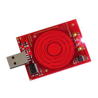
Capacitive-Touch Color Wheel Implementation
Brand:
Infineon
| Category:
Microcontrollers
| Size: 2.1 MB
Table of Contents
Table of Contents
4
1 Introduction
5
Overview
5
2 Color Wheel Features
6
3 Implementation of Color Wheel Software
7
Touch Detection Methodology (Using Touch-Wheel and LEDTS ROM Library)
7
Touch Detection Methodology for the Centre Button
7
Touch Detection Methodology for the Touch-Wheel
8
Touch-Wheel Library
9
Calc_Touchwheel() Function
9
Calc_Compensation() Function
9
Rgb Led
10
Overview Flow Chart of Color Wheel Software Code
11
4 Modifying Color Wheel Software Code
12
User-Defined Parameters
12
Dave-Bench Tool
12
5 Downloading Modified Color Wheel Software Code
15
Access Code to UART BSL Mode
15
6 Implementation of Color Wheel with XC822T
17
Real-Time Clock (RTC) Module
17
Power Saving Control Module
17
CCU6 Module
17
Interrupt System Module
17
UART Module
17
LED and Touch-Sense Controller Unit Module
17
7 Schematics and Layout of the Color Wheel Board
18
8 Summary
21
Advertisement
Infineon XC800 Series Manual (28 pages)
Brand:
Infineon
| Category:
Microcontrollers
| Size: 1.05 MB
Advertisement
Related Products
Infineon XC886
Infineon XC822T
Infineon XC886CLM
Infineon XC888CLM
Infineon XC866
Infineon XC800 AP08113
Infineon XC866-1FR
Infineon XC866-4FR
Infineon XC888
Infineon XC2236N
Infineon Categories
Motherboard
Microcontrollers
Computer Hardware
Control Unit
Controller
More Infineon Manuals
Login
Sign In
OR
Sign in with Facebook
Sign in with Google
Upload manual
Upload from disk
Upload from URL