Table of Contents
Advertisement
Quick Links
Installation and Maintenance Instructions
CONTENTS
SAFETY CONSIDERATIONS . . . . . . . . . . . . . . . . . . . 1
GENERAL . . . . . . . . . . . . . . . . . . . . . . . . . . . . . . . . . . . 2
INSTALLATION . . . . . . . . . . . . . . . . . . . . . . . . . . . . . . . 6
Step 1 - Unpack and Inspect Units . . . . . . . . . . . . 6
Step 2 - Position the Unit . . . . . . . . . . . . . . . . . . . . 6
Step 3 - Mount the Unit . . . . . . . . . . . . . . . . . . . . . . 6
Step 4 - Connect Piping . . . . . . . . . . . . . . . . . . . . . . 8
ELECTRICAL REQUIREMENTS . . . . . . . . . . . . . . . 16
Opening the Electrical Control Box . . . . . . . . . . . . 17
Complete Electrical Connections. . . . . . . . . . . . . 17
MDC UNIT ADDRESSING . . . . . . . . . . . . . . . . . . . 21
Setting the Unit Address . . . . . . . . . . . . . . . . . . . . 21
Merged Port Setting. . . . . . . . . . . . . . . . . . . . . . . . 21
TROUBLESHOOTING . . . . . . . . . . . . . . . . . . . . . . 21
LED Indication Lamp Instructions . . . . . . . . . . . . 21
Error Code . . . . . . . . . . . . . . . . . . . . . . . . . . . . . . . 21
SW8/SW9 Query Instruction . . . . . . . . . . . . . . . . . 21
TEST RUN . . . . . . . . . . . . . . . . . . . . . . . . . . . . . . . . 21
APPENDIX A - DIP SWITCH SETTINGS. . . . . . . . 22
SAFETY CONSIDERATIONS
Improper installation, adjustment, alteration, service,
maintenance, or use can cause explosion, fire, electrical shock,
or other conditions that may cause death, personal injury, or
property damage. The qualified installer or agency must use
factory authorized kits or accessories when modifying this
product.
Follow all safety codes. Wear safety glasses, protective
clothing, and work gloves. Use quenching cloth for brazing
operations. Have fire extinguisher available. Read these
instructions thoroughly, and follow all warnings or cautions
included in literature and attached to the unit. Consult local
building codes and the current editions of the National
Electrical Code (NEC) ANSI/NFPA (American National
Standards Institute/National Fire Protection Association) 70.
For Canada, refer to the current editions of the Canadian
Electrical Code CSA (Canadian Standards Association) C22.1.
Understand the signal words -
.
identifies the most serious hazards,
CAUTION
DANGER
which will result in severe personal injury or death.
signifies hazards that could result in personal injury
WARNING
Manufacturer reserves the right to discontinue, or change at any time, specifications or designs without notice and without incurring obligations.
Catalog No. 19-40VMD001-01
Page
,
, and
DANGER
WARNING
Printed in U.S.A.
Form 40VMD-4SI
Multiport Distribution Controller for
Variable Refrigerant Flow (VRF) Systems
or death.
CAUTION
could result in minor personal injury or product and property
damage.
Recognize safety information. This is the safety-alert
symbol (
). When this symbol is displayed on the unit and in
instructions or manuals, be alert for the potential of personal
injury. Installing, starting up, and servicing the equipment can
be hazardous due to system pressure, electrical components,
and equipment location.
Electrical shock can cause personal injury and death. Shut
off all power to this equipment during installation. There
may be more than one disconnect switch. Tag all
disconnect locations to alert others not to restore power
until work is completed.
When installing the equipment in a small space, provide
adequate measures to avoid refrigerant concentration
exceeding safety limits due to refrigerant leak. In case of
refrigerant leak during installation, ventilate the space
immediately. Failure to follow this procedure may lead to
personal injury.
DO NOT USE TORCH to remove any component. System
contains oil and refrigerant under pressure.
To remove a component, wear protective gloves and
goggles and proceed as follows:
a. Shut off electrical power to unit.
b. Recover refrigerant to relieve all pressure from
system using both high-pressure and low-pressure
ports.
c. Traces of vapor should be displaced with nitrogen
and the work area should be well ventilated.
Refrigerant in contact with an open flame produces
toxic gases.
d. Cut component connection tubing with tubing cutter
and remove component from unit. Use a pan to catch
any oil that may come out of the lines and as a gage
for how much oil to add to the system.
e. Carefully unsweat remaining tubing stubs when
necessary. Oil can ignite when exposed to torch
flame.
Failure to follow these procedures may result in personal
injury or death.
Pg 1
40VMD006-016
is used to identify unsafe practices, which
WARNING
WARNING
WARNING
3-19
Replaces: 40VMD-3SI
Advertisement
Table of Contents

Related Manuals for Carrier 40VMD006-016


Summary of Contents for Carrier 40VMD006-016
-
Page 1: Table Of Contents
40VMD006-016 Multiport Distribution Controller for Variable Refrigerant Flow (VRF) Systems Installation and Maintenance Instructions CONTENTS or death. is used to identify unsafe practices, which CAUTION could result in minor personal injury or product and property Page damage. SAFETY CONSIDERATIONS ....1 Recognize safety information. -
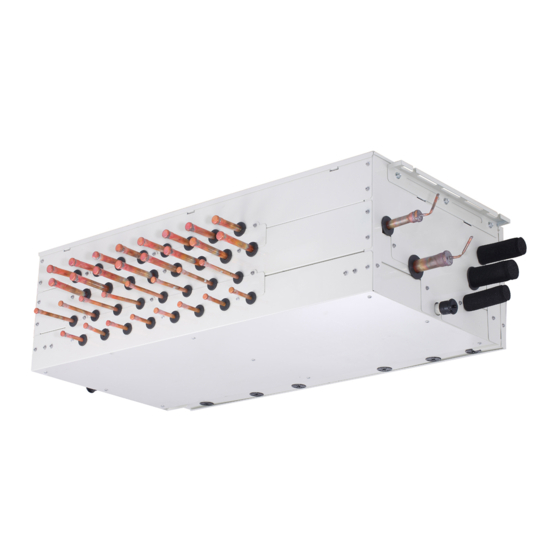
Page 2: General
GENERAL CAUTION The 40VMD multiport distribution controller (MDC) is a distribution box for refrigerant to multiple indoor fan coil units DO NOT re-use compressor oil or any oil that has been installed in a given heat recovery system. exposed to the atmosphere. Dispose of oil per local codes equipment initially protected... - Page 3 Table 1 — 40VMD Physical Data (Sub) UNIT 40VMD 006S 008S 010S 016S POWER SUPPLY (V-Ph-Hz) 208/230-1-60 NUMBER OF PORTS UNIT 46-1/2 x 12-3/4 x 22-5/8 Unit Dimensions, W x H x D (in.) 37 x 12-3/4 x 22-5/8 53-7/8 x 18 x 33-1/8 Packing Dimensions, W x H x D (in.) 44-1/2 x 18 x 33-1/8 137/209...
- Page 4 1 -5/8 DIMENSIONS (in.) 40VMD MODEL SIZE 27-1/2 33-7/9 22-5/8 12-7/8 NOTE: All dimensions shown in inches. Fig. 3 —40VMD Dimensional Drawing (Sub MDC)
- Page 5 Table 2 — Components Shipped With Unit NAME SHAPE QUANTITY FUNCTION Same as MDC Adapter pipe for liquid line ports Use for indoor unit (capacity 05~15Btu/h). Same as MDC Adapter pipe for gas line ports Adapter pipe for liquid line Use for the connecting between the main MDC and 1 sub Adapter pipe for low pressure line MDC unit (available only with the sub MDC).
-
Page 6: Installation
INSTALLATION • Allow adequate space for installation, service clearance, piping, and electrical connections. For specific unit Step 1 — Unpack and Inspect Units — Units are dimensions, refer to Table 1 and Fig. 2. Allow clearance packaged for shipment to avoid damage during normal transit according to local and national codes. - Page 7 Nitrogen Purge for MDC Brazing — • Expansion Valves (EXVA~C) in MDC units are shipped from factory and opened to 120 pulses • Expansion valves for indoor units also have an initial opening from the factory • During brazing, purge with high-purity nitrogen from ODU high and low pressure service valves. Recommended nitrogen flow rate is approximately 1.76 ft /h*.
-
Page 8: Step 4 - Connect Piping
When connecting refrigerant piping follow these guidelines: • The refrigerant piping should be dry and free of dust and other impurities. • The number of bends in the refrigeration piping must be less than 15. • The bending angle of the refrigerant pipe should not ... - Page 9 • Before connecting piping between the indoor units and Table 5 — Connecting Gas Pipes to the Indoor Unit the MDC, remove the brazed cap as shown in Fig. 8. INDOOR Depending on the size of the connecting pipe, the brazed UNIT cap may be left on or removed.
-
Page 10: Twinning Mdc Ports
TWINNING MDC PORTS PIPING BETWEEN MDC AND SUB MDC — Three pipes are used to connect the main MDC and the sub MDC. Selection of the Sub MDC should follow the requirements of CAUTION Table 9. For connecting the sub MDC to main MDC, use the high pressure, low pressure, and liquid pipes as shown in Figs. - Page 11 Gas pipe Gas pipe High pressure High pressure pipe pipe Liquid pipe Liquid pipe Low pressure Main MDC Low pressure Sub MDC pipe pipe Indoor unit Liquid pipe Liquid pipe Drain pipe Drain pipe Low pressure High pressure Indoor Outdoor unit unit Fig.
- Page 12 Table 12 — Connecting Low Pressure Pipes Table 13 — Connecting High Pressure Pipes Between Main MDC and Sub MDC Between Main MDC and Sub MDC INDOOR INDOOR UNIT UNIT CONNECTION DIAGRAM CONNECTION DIAGRAM CAPACITY CAPACITY (kBtu/h) (kbtu/h) 73~126 73~108 127~168 109~168 LEGEND...
- Page 13 Check valves ODU Side SV1B-1 IDU Side Gas/Liquid separator SV1A-1 HEX1 HEX2 SVmB-n EXVA SVME SVmA-n Check valves SV1B-1 SV1A-1 HEX2 SVmB-n EXVA SVmA-n LEGEND EXV* — Expansion Valve — Heat Exchanger — Pressure Sensor SV*A-*, SV*B-*, SVM*, SVP — Solenoid Valve —...
- Page 14 Outdoor Unit NO.2 Sub MDC Unit MDC-Indoor MDC-Main MDC or Sub MDC Indoor Indoor Indoor Indoor Indoor NO.2 Sub MDC Unit Main MDC Sub MDC NO.1 NO.2 NO.3 NO.4 NO.5 5 4 3 NO.1 Sub MDC Unit NO.1 Sub MDC Unit MDC-Indoor MDC-Main MDC or Sub MDC Indoor...
-
Page 15: Piping Between Mdc And Outdoor Unit
PIPING BETWEEN MDC AND OUTDOOR UNIT Table 15 — Connecting High Pressure Pipes with the Outdoor Unit CAUTION OUTDOOR UNIT When connecting from an indoor unit to an outdoor unit, CONNECTION DIAGRAM CAPACITY the isolation valve at the outdoor unit should be in the (kBtu/h) closed position throughout the refrigerant piping process. -
Page 16: Electrical Requirements
Table 16 — Connecting Low Pressure Pipes with the Outdoor Unit WARNING OUTDOOR UNIT All units must be wired strictly in accordance with the CAPACITY CONNECTION DIAGRAM wiring diagram furnished with the unit. Any wiring (kBtu/h) different from the wiring diagram could result in personal injury and property damage. -
Page 17: Opening The Electrical Control Box
Opening the Electrical Control Box Cover — 4. Push the cover about 1/2 inches and then lift up the cover as shown in Fig. 19. Follow the steps below when removing the top cover. 1. Remove the screws as shown in Fig. 16. Fig. - Page 18 Note:24v AC Power z i l l l o Touch Screen Outdoor Unit Wired Controller HA HB Indoor unit 1# Indoor unit 2# To No.1 indoor Main MDC unit To outdoor To No.2 Indoor unit 3# indoor To No.3 indoor To Sub MDC Indoor unit 4# wired controller...
- Page 19 CN45 CN1 CN41 T1 T2 EXVA CN20 CN25 CN27 CN53 CN52 CN51 T1 T2 WATER EXVA EXVB EXVC Fig. 23 —006, 008, 010 Typical Wiring Diagram...
- Page 20 CN20 CN25 CN27 CN53 CN52 CN51 T1 T2 WATER EXVA EXVB EXVC CN20 CN25 CN27 CN53 CN52 CN51 T1 T2 WATER EXVA EXVB EXVC Fig. 24 — Size 016/016L Typical Wiring Diagram...
-
Page 21: Mdc Unit Addressing
MDC UNIT ADDRESSING Table 21 — MDC Query Codes Setting the Unit Address — The address switch [S8] DESCRIPTION of each MDC unit is set to “00” when the unit is shipped from DISPLAYED COMMENT First and Third and the factory. Second Digit Fourth Digit •... -
Page 22: Appendix A - Dip Switch Settings
— 2 Ports Twinned Together Fig. A — S1, S3, S5, and S7 Settings © Carrier Corporation 2019 Manufacturer reserves the right to discontinue, or change at any time, specifications or designs without notice and without incurring obligations. Catalog No. 19-40VMD001-01 Printed in U.S.A.
Need help?
Do you have a question about the 40VMD006-016 and is the answer not in the manual?
Questions and answers