Table of Contents
Advertisement
economical
leading design
clean air approved
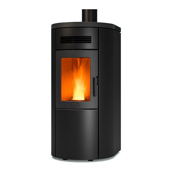
Dual 7 Wood Pellet Fire
Owners & Installation Manual
PLEASE READ THIS ENTIRE MANUAL BEFORE INSTALLATION, AND USE OF THIS WOOD PELLET FIRE.
FAILURE TO FOLLOW THESE INSTRUCTIONS COULD RESULT IN PROPERTY DAMAGE, BODILY INJURY,
OR EVEN DEATH.
Contact your local building or fire official about restrictions and installation requirement in your area.
Advertisement
Chapters
Table of Contents

Related Manuals for Ravelli Dual 7


Summary of Contents for Ravelli Dual 7
- Page 1 Dual 7 Wood Pellet Fire Owners & Installation Manual PLEASE READ THIS ENTIRE MANUAL BEFORE INSTALLATION, AND USE OF THIS WOOD PELLET FIRE. FAILURE TO FOLLOW THESE INSTRUCTIONS COULD RESULT IN PROPERTY DAMAGE, BODILY INJURY, OR EVEN DEATH.
- Page 2 If you are a not a registered pellet re installer, and do not have legitimate access to the necessary passwords to install and program the Dual 7 Wood Pellet Fire, you MUST NOT install or attempt to install this fire.
-
Page 3: Table Of Contents
Owner’s section - Table of Contents Introduction................5 1.1 Specifications................ 5 Safety Warnings & Recommendations....... 6 Installation................... 6 2.2 Deciding where to locate your wood pellet burning fire.. 7 2.3 Ash.................... 7 2.4 Clinkering.................. 7 2.5 Filling Fuel Hopper.............. 7 Flammable Liquids..............8 2.7 Operating Instructions............... 8 Safety Devices................Responsibilty................2.10 Spare Parts................. What are Wood Pellets?............ - Page 4 Operating your Pellet Fire............. 15 Preliminary Operation..............15 Description of Handheld Set............15 Handheld Touch Radio Initialization........... 16 Description of the Display............16 6.5 Time and Date Settings............... 17 Loading the Auger............... 18 6.7 Setting Operating Temperature and Power....... 19 Turning the Device on..............19 Operating Phases of the Stove..........6.9.1 Alarms ..................
-
Page 5: Introduction
Introduction This manual is designed for both the technician and the home owner. Please read this entire manual before installing or operating your Ravelli Dual 7 Freestanding Wood Pellet Burning Stove. Failure to follow these instructions may result in property damage, bodily injury or even death. -
Page 6: Safety Warnings & Recommendations
Safety Warnings & Recommendations Pellet quality is important, please read the following: Your pellet heater has been designed to burn ¼” (6mm) diameter wood pellets, manufactured to the AS/NZS 4014.6 only. DO NOT use this appliance as an incinerator. DO NOT use unsuitable and non recommended fuels, including liquid fuels, as this will void any warranties stated in the manual. -
Page 7: Deciding Where To Locate Your Wood Pellet Burning Fire
This will assist the appliance to perform to the level required. As the Dual 7 heats space by convecting air through the top of the unit, the heater should face the majority of the area to be heated. -
Page 8: Flammable Liquids
Flammable Liquids Never use gasoline, gasoline – type lantern fuel, kerosene, charcoal lighter fluid or similar liquids to start or “freshen” up a fire in the stove. Keep all such liquids well away from the stove while it is use. Operating Instructions The stove is completely automated and will self-regulate the ignition phase, five levels of power and... -
Page 9: What Are Wood Pellets
The pellets must be transported and stored in a dry place. They swell on contact with any moisture and cannot be used. They must always be protected from moisutre, both during transport and in storage. Ravelli recommends using a pellet with a diameter of 6 mm for the stove. The Components of the Stove... -
Page 10: Pellet Combustion
Pellet Combustion Combustion is simply a chemical reaction between combustible and carburant. The result of this reaction is the heat. The three elements that are required for combustion are: -Combustible (pellet) -Carburant (oxygen available in the air) -Ignition (electrical resistance for ignition) PELLET To achieve combustion, the combustible and the carburant must be available in the correct proportions. -
Page 11: Maintenance And Cleaning
Maintenance and Cleaning Before carrying out any maintenance, take the following precautions: Maintenance and Cleaning Make sure that the stove has been turned off, and that the general power supply has been disconnected • (Ensure that the plug is disconnected from the socket, thus avoiding accidental electric shocks). Before carrying out any maintenance, take the following precautions: •... -
Page 12: Cleaning The Ash Drawer
Rengøring af askeskuffen: Cleaning the ashes drawer: Reinigung des Aschekastens: Askeskuffen skal rengøres hver 30. dag. The ashes drawer must be cleaned every days, depending on the length of time the stove is used, Det afhænger i alle tilfælde af hvor længe The ashes drawer must be cleaned every 30 Der Aschekasten muss alle 30 Tage gereinigt and the type of pellet used. -
Page 13: Acess To The Inspection Hatches For Cleaning The Smoke
Dual 7 Dual 7 di pulizia. Ravelli pour effectuer ce genre de N.B.: Utilizzare solo un aspiratore di nettoyage. N.B. : Utiliser uniquement un Remove the side panels and release the two screws that secure the hatches to the body of the pellet tipo aspiracenere. -
Page 14: How To Load Pellets
Lid of pellet tank Iron slide Folleto dedicado al modelo Brochure til model Opuscolo dedicato modello Dual 7 Dual 7 Dual 7 How to remove Firex Remove and clean the flame trap regularly Fase A / Phase A... -
Page 15: Operating Your Pellet Fire
Vers. 01 del 07/04/15 Manuale utente PALMARE IDRO TOUCH RADIO Operating your Pellet Fire Pag.22 Vers. 01 del 07/04/15 Manuale utente PALMARE IDRO TOUCH RADIO Preliminary Operations Pag.22 Preliminary Operations Wiring Preliminary Operations Wiring power cord of the stove. What to check befor turning on the stove power cord of the stove. -
Page 16: Handheld Touch Radio Initialization
Vers. 01 del 07/04/15 Manuale utente PALMARE IDRO TOUCH RADIO Pag.23 Handheld touch radio initialization Handheld touch radio initialization In order to operate correctly, the handheld set should be interfaced with the electronic board installed inside the stove. For this FIRST INSTALLATION? PRESS THE KEY RADIO ADJ ON THE STOVE... -
Page 17: Time And Date Settings
When you replace the batteries, you do not have to run the initialization procedure of the handheld set. In this case, when on display appears the message “FIRST INSTALLATION ?”, select NO Description of the display Description of the display The display of the handheld set is described below (in stand-by mode): After 5 minutes of inactivity, the display of the handheld set turns dark, switching to “SLEEP”... - Page 18 Time and date setting Time and date setting Below are given the steps for accessing the relative menu. MENU USER USER SCREW FEEDING COMFORT CLIMA USER CHRONOTHERMOSTAT SETTINGS MANUFACTURER AIR-PELLET SET ENGINEER STOVE STATE Press the key Press the key “access menu” to Press the key “selection”...
-
Page 19: Loading The Auger
Vers. 01 of:07.04.14 User’s manual HANDHELD TOUCH RADIO Loading the Auger Pag.22 Loading the auger Carry out this operation to facilitate stove’s first start operations; You should also check that you have introduced pellets into the hopper and wait until the stove is in “SHUTDOWN” or “FINAL CLEANING” mode. The number expressed in sec- onds indicates the rotation time of the infeed screw during the first loading cycle. -
Page 20: Operating Phases Of The Stove
Vers. 01 of:07.04.14 User’s manual HANDHELD TOUCH RADIO Pag.23 Operating Phases of the Stove Operating phases of the appliance Modulation During the work phase, the appliance should reach the room temperature set; when this condition is met, the stove switches to MODULATION mode in which fuel consumption and ventilation are minimum. - Page 21 Vers. 01 of:07.04.14 User’s manual HANDHELD TOUCH RADIO Pag.24 The first setting allows the activation of the CLIMATE COMFORT function. This function is intended to ensure that the room tem -perature set is maintained steady upon setting the maximum period of “X” minutes (SWITCH-OFF DELA Y: 5 MIN) before switch-ing to ECO STOP phase.
- Page 22 Vers. 01 of:07.04.14 User’s manual HANDHELD TOUCH RADIO Pag.25 Settable switch-on program Settable switch-off program Day of the week with active program Number of "chrono" program (1-2-3-4) Setting the power upon programming Setting ambient temperature By pressing the Increment key you can change each value and, at step 3, enable the days of the week; By pressing the Increment key you can change each value and, at step 3, enable the days of the week;...
- Page 23 Vers. 01 of:07.04.14 User’s manual HANDHELD TOUCH RADIO Pag.26 Stove State Below are given the steps for accessing the relative menu starting from Stand-By mode. MENU USER USER SCREW FEEDING SCREW FEEDING USER CHRONOTHERMOSTAT CHRONOTHERMOSTAT MANUFACTURER AIR-PELLET SET AIR-PELLET SET ENGINEER STOVE STATE STOVE STATE...
- Page 24 Vers. 01 of:07.04.14 User’s manual HANDHELD TOUCH RADIO Pag.27 Settings Below are given the steps for accessing the relative menu starting from Stand-By mode. MENU USER USER SCREW FEEDING COMFORT CLIMA USER CHRONOTHERMOSTAT SETTINGS MANUFACTURER AIR-PELLET SET ENGINEER STOVE STATE Press the key Press the key “confirm”...
- Page 25 Vers. 01 of:07.04.14 User’s manual HANDHELD TOUCH RADIO Pag.28 Single ducting (function present only in models equipped with single ducting system) The stoves with optional fan employ the natural convection system that ensures a considerable heat output in the environment with the total absence of noise generated by room ventilation.
- Page 26 % of ventilation (see the MAN and AUT control table) Cubic capacity priority among rooms Stove phase synthetical layout PHASE DESCRIPTION The stove is in the switch off phase and the cooling phase has not been completed yet. FINAL CLEANING SWITCH ON The heater pre-heating phase has started and the pellets start to fall into the grate.
- Page 27 Vers. 01 of:07.04.14 User’s manual HANDHELD TOUCH RADIO Pag.36 PHASE DESCRIPTION Switch-on is requested but with the stove in cooling phase; once this condition is met, it START/RESTART WAIT restarts automatically. The HOT restart phase is activated. SWITCH ON RESTART Functioning is similar to the SWITCH ON phase The maximum fume temperature threshold has been reached.
-
Page 28: 6.9.1 Alarms
6.9.1 Alarms Vers. 01 of:07.04.14 User’s manual HANDHELD TOUCH RADIO Pag.37 Alarms (table with reference codes) TITLE REASON SOLUTION TRIAL - No voltage during work phase - Press the switch off key and switch on boiler switch-on. AL 01 BLACK OUT - If the problem persists, contact the Support Service - The fume probe is malfunctioning... - Page 29 Vers. 01 of:07.04.14 User’s manual HANDHELD TOUCH RADIO Pag.38 In the case of alarm 07 THERMAL BREAKER below shows the location where to operate to reset the thermal switch with manual reset. Manual reset thermal breaker Unscrew the protective cap and press the button to reset the thermal breaker Unscrew the protective cap and press the button to reset the thermal breaker...
-
Page 30: Maintenance Record
7. Maitenace record Maintenance Record DATE WORK CARRIED OUT SIGNATURE... -
Page 31: Warranty Information
Auger Motor manufacture. After installation, if any covered components Circuit Board, manufactured by Ravelli are found to be defective in decal & mounting materials or workmanship during the applicable warranty bracket period, Pellet... -
Page 32: Warranty Exclusions
EXCEPT TO THE operation, abuse, misuse, continued operation with EXTENT PROVIDED BY LAW, Pellet Solution damaged, corroded or failed components, accident, Ravelli MAKES NO EXPRESS WARRANTIES OTHER or improperly/incorrectly performed repairs; (5) THAN THE WARRANTY SPECIFIED HEREIN. environmental conditions, inadequate ventilation,... -
Page 33: Proof Of Purchase/Warranty
9. Proof of Purchase/Warranty Use this page to note down the details of your wood pellet fi re purchase, and attach the receipt and any other documents/ business cards from the retailer that sold you the fi re. Name of Store where Pellet fi re was purchased: ....................... Date of Purchase: ....................... - Page 34 Table of Contents Dimensions R avelli Dual 7............... Deciding where to locate your wood pellet burning stove: ........36 Clearances to Combustibles – Ravelli Dual 7 Freestanding .........36 Exhaust and Fresh Air Intake Locations ..............36 Installation ....................37 Dimensions – Dual 7 F reestanding ...............37...
- Page 35 V - Hz 220 – 50 Tank capacity Space Heating The data shown above are indicative and not binding. Ravelli reserves the right to make any for the purpose of improving the performances of the product. FLOW 3/4 DUAL 7...
-
Page 36: Deciding Where To Locate Your Wood Pellet Burning Stove
This will optimize heat circulation. Check clearances to combustibles. Clearances to Combustibles – Ravelli Dual 7 Freestanding This pellet heater requires floor protection which must be non-combustible, extending beneath the stove the full width and depth of the unit including (150mm) in front for ember protection. -
Page 37: Installation
Minimum clearances shown are in millimetres. All Ravelli fires tested AS/NZS 2918:2001. a guide only. Refer to the Installation and Operation Manual supplied with every Ravelli Pellet Fire or if in doubt, consult your Pellet Retailer. Dual Pellet Fire Clearance to Combustibles... -
Page 38: Minimum Clearance To Combustibles
Location of a power source • Dual 7 has a convection fan which blows air through tubes in the direction that the fire faces, for optimum performance this location should be in a large room, facing the area to be heated •... -
Page 39: Internal Standard Flue Kit (50Sbd/N)
50S D/N Internal Standard Flue Kit Dual/Natural This flue kit may be used in new and replacement applications in rooms with stud height of 2.4m. The overall height of the flue is 3.6m. The visible flue is finished in black and the ceiling plate is white. The support angles for securing the liner to the ceiling are not shown. -
Page 40: External Standard Flue Kit (51Ita)
51ita 51ita External Standard Flue Kit This flue kit may be used in new and replacement applications with the flue penetrating the wall behind the fire, running vertically up an outside wall and penetrating the soffit. The overall height of the flue is 3.6m. -
Page 41: Seismic Restraint
Seismic Restraint All installation scenario for Dual 7 require the use of hold-down anchors Fixing to Concrete Floor: • Minimum M8 expansion anchors (M10 recommended) or min M8 epoxy- set anchors. • Approved Anchors: Expansion Anchors-Ramset Dynabolt and Trubolt, Hilti HAS. -
Page 42: How To Mount The Side Panels
Brochure for Broschüre für Modell Opuscule dédié au modèle Dual 7 model Dual 7 Dual 7 2.12 How to mount the side panels... -
Page 43: Installation Data Sheet
Installation Data Sheet Name of Owner: Name of Dealer: ________________________________ ________________________________ Address: Address: ________________________________ ________________________________ ________________________________ ________________________________ ________________________________ ________________________________ ________________________________ ________________________________ Phone: Phone: ________________________________ ________________________________ Model: __________________________ Name of Installer: ________________________________ Serial Number: ____________________ Address: Date of Purchase: __________ (dd/mm/yy) ________________________________ Date of Installation: _________ ________________________________... -
Page 44: Maintenance Record
Maintenance Record DATE WORK CARRIED OUT SIGNATURE... -
Page 45: Producer Statement And Warranty Registration Form
PRODUCER REGISTRATION FORM This form must be completed and returned for every installation to qualify for warranty. Post to: P O Box 11-245, Sockburn, Christchurch Email to: info@pelletfiresolutions.co.nz Customer Details: Customer Name: Postal Address: Installation Address: Phone Number Cell Phone Email Address Declaration by Owner: I hereby certify the above particulars are true and correct.
Need help?
Do you have a question about the Dual 7 and is the answer not in the manual?
Questions and answers