Table of Contents
Advertisement
Advertisement
Table of Contents

Related Manuals for Sutter Instrument MPC-325 Series


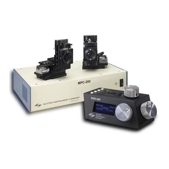
Summary of Contents for Sutter Instrument MPC-325 Series
- Page 1 MPC-325 Series Multi Motorized-Micromanipulator Control System Operation Manual Rev. 3.20f (20200303) One Digital Drive Novato, CA 94949 Voice: 415-883-0128 Web: www.sutter.com Fax: 415-883-0572 Email: info@sutter.com MPC-325 SERIES OPERATION MANUAL – REV. 3.20F (20200303)
- Page 2 Copyright © 2020 Sutter Instrument Company. All Rights Reserved. MPC-325 SERIES OPERATION MANUAL – REV. 3.20F (20200303)
-
Page 5: Disclaimer
Do not allow unauthorized and/or untrained operative to use this device. Any misuse will be the sole responsibility of the user/owner and Sutter Instrument Company assumes no implied or inferred liability for direct or consequential damages from this instrument if it is operated or used in any way other than for which it is designed. -
Page 6: Operational
Always wear safety glasses when using sharp glass micropipettes with pressure microinjectors. Do not handle the manipulator mechanical while the power is on, and take care to ensure no cables pass close to the mechanical manipulator. MPC-325 SERIES OPERATION MANUAL – REV. 3.20F (20200303) -
Page 7: Other
Some applications, such as piezo-impact microinjection call for the use of mercury in the micropipette tip. The use of any hazardous materials with any Sutter Instrument’s instrument is not recommended and if undertaken is done so at the users’ own risk. - Page 8 (This page intentionally left blank.) MPC-325 SERIES OPERATION MANUAL – REV. 3.20F (20200303)
-
Page 9: Table Of Contents
Handling Micropipettes .......................... 5 1. INTRODUCTION ........................... 11 1.1 Structure of the MPC-325 Documentation Package ..............11 1.2 Components of the MPC-325 Series ..................... 11 2. MPC-200 MULTI-MANIPULATOR CONTROLLER AND ROE-200 INPUT DEVICE OPERATIONS ............................ 13 2.1 Electrical Connections and Initial Operating Instructions ............13 2.2 Initial Operating Instructions ....................... - Page 10 Figure 2-2. Top view of ROE-200......................15 Figure 2-3. Side view of ROE-200......................17 Figure 2-4. Configuration switches on rear of MPC-200 controller cabinet........19 Figure 2-5. Configuration switches (rear of MPC-200 controller)............21 MPC-325 SERIES OPERATION MANUAL – REV. 3.20F (20200303)
- Page 11 Table 6-18 Command to disable current-position streaming data during an ‘S’-command-initiated move............................43 Table 6-19 Command to disable current-position streaming data during an ‘S’-command-initiated move............................43 Table 5-17 Set ROE MODE (‘L’) command..................43 MPC-325 SERIES OPERATION MANUAL – REV. 3.20F (20200303)
- Page 12 Table E-6. Microns/microsteps conversion factors (multipliers)............60 Table E-7. Travel distances and bounds....................60 Table E-8. Travel speeds.......................... 60 Table E-9. MPC-325 (MPC-200) external-control commands............. 61 Table E-10.Straight-line move ‘S’ command speeds................64 MPC-325 SERIES OPERATION MANUAL – REV. 3.20F (20200303)
-
Page 13: Introduction
Two DB-25 cables (connect adapter boxes to the controller). § Two X285210 mounting adapter plates and hardware to attach mechanicals to their mounting surfaces § Two X285204 four-inch dovetail extensions for mounting headstages § Two dovetail rod clamps MPC-325 SERIES OPERATION MANUAL – REV. 3.20F (20200303) - Page 14 Once these screws have been removed, handle the micromanipulator with care. The mechanism can be damaged if the axes are moved with the screws in place. MPC-325 SERIES OPERATION MANUAL – REV. 3.20F (20200303)
-
Page 15: Mpc-200 Multi-Manipulator Controller And Roe-200 Input Device Operations
As the power switch is the only control you will need to access on the MPC-200, the controller can ultimately be placed in an out of the way location (e.g., under your bench). MPC-325 SERIES OPERATION MANUAL – REV. 3.20F (20200303) - Page 16 Conversely, when you make prolonged, rapid turns of the ROE knob, the controller/ROE automatically accelerates to maximum speed to allow for prolonged, long distance movements. This would be most useful for manual pipette exchange. MPC-325 SERIES OPERATION MANUAL – REV. 3.20F (20200303)
-
Page 17: Main Controls On The Roe-200
Z-axis, maximal right on the X-axis (maximal left on a left- handed manipulator) and maximal front on the Y-axis. The stereotypic path of the movement MPC-325 SERIES OPERATION MANUAL – REV. 3.20F (20200303) -
Page 18: Black Selector Switches
MODE 5 or 6 will provide the necessary dexterity of movement for the final approach to a cell. The current MODE setting is displayed in the upper right of the ROE-200 display. MPC-325 SERIES OPERATION MANUAL – REV. 3.20F (20200303) -
Page 19: Other Controls On The Roe-200
(12500 (X), 12500 (Y), 12500 (Z)), the center of travel of each axis. If the unit is turned off or STOP/SET is pressed during the running of CENTER, the unit will MPC-325 SERIES OPERATION MANUAL – REV. 3.20F (20200303) -
Page 20: Controls On The Mpc-200
Switch 1. For any new switch settings to take effect, the controller must be powered off and on. The figure below shows the two banks of switches on the back of the MPC-200 controller. MPC-325 SERIES OPERATION MANUAL – REV. 3.20F (20200303) -
Page 21: Figure 2-4. Configuration Switches On Rear Of Mpc-200 Controller Cabinet
1, 2, 3 and 4. As indicated in the inset to the left of the table, the angles fall into two different quadrants according to whether the angles are more or less steep than 45 degrees. MPC-325 SERIES OPERATION MANUAL – REV. 3.20F (20200303) -
Page 22: Table 2-1. Configuration Switch Settings For Different Angles Of Steepness
1, a clockwise turn of the knob produces an increment in the display. An increment in the display coincides with movement downward in the Z axis, MPC-325 SERIES OPERATION MANUAL – REV. 3.20F (20200303) -
Page 23: Figure 2-5. Configuration Switches (Rear Of Mpc-200 Controller)
Figure 2-5. Configuration switches (rear of MPC-200 controller). MPC-325 SERIES OPERATION MANUAL – REV. 3.20F (20200303) - Page 24 (This page intentionally blank.) MPC-325 SERIES OPERATION MANUAL – REV. 3.20F (20200303)
-
Page 25: Mp-225/M Manipulator Mechanical Mounting Instructions
To remove the plate, first loosen the locking screws and then pull the mounting plate straight down. The figure above shows the plate removed from the X axis. Once removed, the mounting adapter plate can be secured to any flat surface carrying ¼-20 or 10-32 holes on MPC-325 SERIES OPERATION MANUAL – REV. 3.20F (20200303) -
Page 26: Setting Headstage/Pipette Angle And Pipette Exchange
Z-axis shipping screw holes. You may find it beneficial to move the gate up before you start using your MP-225/M. MPC-325 SERIES OPERATION MANUAL – REV. 3.20F (20200303) -
Page 27: Headstage Mounting
Rod mounted headstages and micro tools are accommodated by use of a rod clamp that fits into the dovetail (not shown). All the headstage adapters and mounting hardware are included with the manipulator and are shipped in a zip lock plastic bag. MPC-325 SERIES OPERATION MANUAL – REV. 3.20F (20200303) -
Page 28: Modular Construction
(middle panel). 4. Reinsert the pins into the holes in the bottom of the Y axis (right panel). 5. Retighten the hex set screws in the sides of the Y-axis. MPC-325 SERIES OPERATION MANUAL – REV. 3.20F (20200303) -
Page 29: Instructions Used In Special Installations Only
MP-225/M, two other minor changes must be made: First, as the X and Y-axes have interchanged with the 90-degree rotation, the wires controlling these two axes must be switched at the connector box. MPC-325 SERIES OPERATION MANUAL – REV. 3.20F (20200303) - Page 30 X (the holes with set screws). Finally, press the two axes firmly together and retighten the setscrews. Now the Y-axis will move forward during the home move and back during the work position move. MPC-325 SERIES OPERATION MANUAL – REV. 3.20F (20200303)
-
Page 31: Operations
4.2 Make It Go Turn on the power using the ON/OFF switch on the front panel of the MPC-200 controller cabinet. MPC-325 SERIES OPERATION MANUAL – REV. 3.20F (20200303) -
Page 32: Basic Operation
4.3.2 Standard Screen ROE-200 MODE:0 Z=00000 X=00000 Y=00000 4.3.3 No Manipulator Connected Screen NO MANIPULATOR DETECTED, PLEASE TURN OFF CONTROLLER ATTACH MANIPULATOR 4.3.4 Diagonal-Mode Screen (DIAGONAL) ROE-200 MODE:0 Z=00000 X=00000 Y=00000 D=00000 MPC-325 SERIES OPERATION MANUAL – REV. 3.20F (20200303) -
Page 33: Move In Progress Screen
4.3.5 Move in progress screen: PLEASE WAIT MOVE IN PROGRESS 4.3.6 Setting Work Position (WORK POS) ROE-200 DEVICE LOCKED (HOLD WORK POS. FOR 2s TO UNLOCK DEVICE) MPC-325 SERIES OPERATION MANUAL – REV. 3.20F (20200303) - Page 34 (This page intentionally blank.) MPC-325 SERIES OPERATION MANUAL – REV. 3.20F (20200303)
-
Page 35: External Control
MPC-200 controller over the USB interface between the computer and the USB connector on the rear of the ROE-200 that’s connected to the MPC-200 controller. The USB device driver for Windows is downloadable from Sutter Instrument’s web site (www.sutter.com). The MPC-325 (MPC-200) requires USB CDM (Combined Driver Model) Version 2.10.00 or higher. -
Page 36: Command Sequence Formatting
Little- Endian enforcement may be needed if running on a Big-Endian system. Some processors (e.g., ARM) can be configured for specific endianess. MPC-325 SERIES OPERATION MANUAL – REV. 3.20F (20200303) -
Page 37: Microsteps And Microns (Micrometers)
MOM objective mover (firmware v3.13 or 3.16, and device Port A only): 21.5mm in all three axes. 5.1 Travel Speed The following table shows the travel speeds for single-, double-, and triple-axis movements for supported devices using orthogonal move commands. MPC-325 SERIES OPERATION MANUAL – REV. 3.20F (20200303) -
Page 38: Commands
1 byte for the number of devices connected followed four bytes containing connected status for Port 1 through 4, and completion indicator (1 byte). MPC-325 SERIES OPERATION MANUAL – REV. 3.20F (20200303) -
Page 39: Get Active Device & Firmware Version ('K') Command
= 1; lower nibble = 0)) Major version number coded in BCD (e.g., if ver. = 3.10, then byte = 0x03 (upper nibble = 0; lower nibble = 3)) Completion indicator 0000 1101 <CR> MPC-325 SERIES OPERATION MANUAL – REV. 3.20F (20200303) -
Page 40: Get Current Position ('C') Command
This command is used to change which device (1- 4) is currently active. The command sequence consists of one byte as shown in the following table, and returns 1 (Ver. below 1.06) MPC-325 SERIES OPERATION MANUAL – REV. 3.20F (20200303) -
Page 41: Move To Controller-Defined Home Position ('H') Command
Move to Command 0101 1001 0089 Work Position Completion indicator 0000 1101 <CR> (‘Y’) The “Home Position” is defined manually on the ROE-200. The “Work Position” is defined manually on the ROE-200. MPC-325 SERIES OPERATION MANUAL – REV. 3.20F (20200303) -
Page 42: Move To Center Position ('N') Command (Fw =< 1.03)
The command sequence consists of thirteen bytes: Command byte followed by three sets of four bytes containing position information in microsteps for X, Y, and Z. MPC-325 SERIES OPERATION MANUAL – REV. 3.20F (20200303) -
Page 43: Move To Specified Position In A Straight Line At Specified Speed ('S') Command
Time of travel (see Note 30ms Error! Reference source not found.) Completion indicator 0000 1101 <CR> (streaming positional data is OFF – see ‘F’ command) once movement completes, or streaming current position data (see ‘O’ MPC-325 SERIES OPERATION MANUAL – REV. 3.20F (20200303) -
Page 44: Interrupt Move ('^C') Command
5.2.13 Turn OFF S-Move command streaming data (‘F’) Command This command is sent before the ‘S’ (straight-line move) command to disable the return of current position streaming while an ‘S’ command initiated move is in progress. Command MPC-325 SERIES OPERATION MANUAL – REV. 3.20F (20200303) -
Page 45: Turn On S-Move Command Streaming Data ('O') Command
0-9 0000 0000 0000 – to finest/slowest) 0000 1001 0009 Task-completion indicator 0000 1101 <CR> 5.2.16 Command Notes The following list of notes apply to all the external control commands described in this chapter. MPC-325 SERIES OPERATION MANUAL – REV. 3.20F (20200303) - Page 46 Little-Endian byte order so byte reordering is not necessary before converting to/from 32-bit “long” values. LabVIEW always handles “byte strings” in “Big Endian” byte order irrespective of operating system and CPU, requiring that the four bytes MPC-325 SERIES OPERATION MANUAL – REV. 3.20F (20200303)
- Page 47 Multi Axis Movement Speed Increase: Specified travel speeds are for single-axis movements. When travel traverses a 45° diagonal within a dual-axis square, speed is increased by 40% (x 1.4), and by 70% (x 1.7) within a triple-axis cube. MPC-325 SERIES OPERATION MANUAL – REV. 3.20F (20200303)
- Page 48 0, so that the resulting data (now 4 bytes) can be treated programmatically as an unsigned 32-bit “long” (C/C++) or “U32” (LabVIEW) data type. All positional data streamed is in Little-Endian bit/byte order MPC-325 SERIES OPERATION MANUAL – REV. 3.20F (20200303)
- Page 49 &pos[3], 1); // X memcpy(&cpxus[1], &pos[4], 1); memcpy(&cpxus[0], &pos[5], 1); memcpy(&cpyus[2], &pos[6], 1); // Y memcpy(&cpyus[1], &pos[7], 1); memcpy(&cpyus[0], &pos[8], 1); memcpy(&cpzus[2], &pos[9], 1); // Z memcpy(&cpzus[1], &pos[10], 1); memcpy(&cpzus[0], &pos[11], 1); MPC-325 SERIES OPERATION MANUAL – REV. 3.20F (20200303)
- Page 50 Endian bit/byte order, while MPC-200 multibyte values are always transcieved in Little-Endian bit/byte order. A single completion indicator byte (ASCII CR) is returned when streaming ends and target position has been reached. MPC-325 SERIES OPERATION MANUAL – REV. 3.20F (20200303)
-
Page 51: Maintenance
As such, it DOES NOT REQUIRE LUBRICATION. Attempting to lubricate any part of the electromechanical assembly will void the warranty and may harm one or more of the motors. MPC-325 SERIES OPERATION MANUAL – REV. 3.20F (20200303) - Page 52 (This page intentionally blank.) MPC-325 SERIES OPERATION MANUAL – REV. 3.20F (20200303)
-
Page 53: Appendix A. Limited Warranty
Warranty work will be performed only at the factory. § The cost of shipment both ways is paid for by Sutter Instrument during the first three months this warranty is in effect, after which the cost is the responsibility of the customer. - Page 54 (This page intentionally blank.) MPC-325 SERIES OPERATION MANUAL – REV. 3.20F (20200303)
-
Page 55: Appendix B. Accessories
X285310 Z-axis horizontal extension BR-AW Rod holding clamp for XenoWorks injectors MP-ROD Rod holder 285HEA Hinged headstage mount For use with MT- or MD-series stands/platforms, or any surface with 1-inch centered holes. MPC-325 SERIES OPERATION MANUAL – REV. 3.20F (20200303) - Page 56 (This page intentionally blank.) MPC-325 SERIES OPERATION MANUAL – REV. 3.20F (20200303)
-
Page 57: Appendix C. Fuse Replacement
(Examples: Bussmann GDC-2A. GMC-2A or S506-2-R (RoHS); or Littelfuse 218 200 or 218 200P (RoHS)) Figure C-1. Rear view of the MPC-200 controller cabinet showing the power entry module and fuse location. MPC-325 SERIES OPERATION MANUAL – REV. 3.20F (20200303) - Page 58 (This page intentionally blank.) MPC-325 SERIES OPERATION MANUAL – REV. 3.20F (20200303)
-
Page 59: Appendix D. Technical Specifications
Table 6-1. MPC-325 Controller cables and receptacles/connectors. Controller Rear Panel Cable Connector Connects to ... Cable Type Cable Port Max. Types Connector/Receptacle Length MPC-200: (Power entry) 3-pin male connector MPC-325 SERIES OPERATION MANUAL – REV. 3.20F (20200303) -
Page 60: Roe-200
“B” receptacle (full- (approx. circuits. Foil receptacle (full-sized) sized) 10 feet) shielding. D.3. ROE-200 Dimensions: 10 x 6 x 4 in (25.4 x 15.24 x 10.16 cm) Weight: 3.5 lbs (1.6 kg) MPC-325 SERIES OPERATION MANUAL – REV. 3.20F (20200303) -
Page 61: Appendix E. Quick Reference
(via the Device factors). Manager if in Windows) and/or programmatically in your application. Microsteps are stored as positive 32-bit values (“long” (or optionally, “signed long”), or “unsigned MPC-325 SERIES OPERATION MANUAL – REV. 3.20F (20200303) - Page 62 MP-x45[S]/M & MP-865/M µmanipulators and MPC-x8 series Command Reference: The following table lists all the stages: 1 µstep = 0.046875 µm; 1 µm = 21.333333333 µsteps. external-control commands for the MPC-325 (MPC- 200). MPC-325 SERIES OPERATION MANUAL – REV. 3.20F (20200303)
- Page 63 (upper nibble = 1; lower nibble = 0)) Major version number coded in BCD (e.g., if ver. = 3.10, then byte = 0x03 (upper nibble = 0; lower nibble = 3)) Completion indicator 0D 0000 1101 <CR> MPC-325 SERIES OPERATION MANUAL – REV. 3.20F (20200303)
- Page 64 9-12 => Time of travel (see Notes) 30ms Completion indicator 0D 0000 1101 <CR> The “Home Position” is defined manually on the ROE-200. The “Work Position” is defined manually on the ROE-200. MPC-325 SERIES OPERATION MANUAL – REV. 3.20F (20200303)
- Page 65 (after sending a command computer and controller (i.e., using exact number of bytes for sequence and before sending the next command). both command sequences and return data (as per the MPC-325 SERIES OPERATION MANUAL – REV. 3.20F (20200303)
- Page 66 The following code multibyte value between the two Endian formats (if Big shows how to extract and convert the 4 BCD digits into usable forms for later comparison without altering the original MPC-325 SERIES OPERATION MANUAL – REV. 3.20F (20200303)
- Page 67 A single completion indicator byte (ASCII CR) is returned cpxus xx xx xx 00 when streaming ends and target position has been reached. 0 1 2 3 cpyus yy yy yy 00 cpzus 0 1 2 3 MPC-325 SERIES OPERATION MANUAL – REV. 3.20F (20200303)
- Page 68 NOTES: MPC-325 SERIES OPERATION MANUAL – REV. 3.20F (20200303)
-
Page 69: Index
Installing and using right angle adapter .... 27 move interruption ........46, 64 multi axis movement speed increase ..45, 64 orthogonal move speed ....... 45, 64 line power (mains) ..........29 MPC-325 SERIES OPERATION MANUAL – REV. 3.20F (20200303) - Page 70 ..............51 operational ............4 weight .............. 57, 58 safety warnings & precautions ......3, 4 MPC-200 controller .......... 57 Setting Headstage/Pipette Angle ......24 ROE-200 ............58 Special installations ..........27 NOTES MPC-325 SERIES OPERATION MANUAL – REV. 3.20F (20200303)
- Page 71 Addendum All Operation Manuals of MPC-200/ROE-200-Based MPC-Series Systems Rev. 1.00 – November 28, 2007 As of Version 3.11 (November 12, 2007) of the firmware for the MPC-200 micromanipulator controller and ROE-200 input device, the CENTER routine associated with the white button on the rear of the ROE-200 has been replaced with a CALIBRATE routine that is less likely to break a pipette.
Need help?
Do you have a question about the MPC-325 Series and is the answer not in the manual?
Questions and answers