
Related Manuals for Sutter Instrument MPC-200


Summary of Contents for Sutter Instrument MPC-200
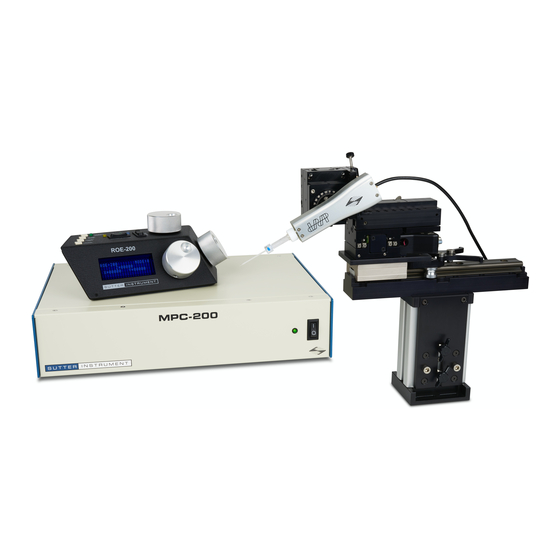
- Page 1 Operations Rev. 1.0b/012004 ( 20070426) MPC-200 ROE-200 Multi-manipulator Controller and Input Device...
- Page 2 Copyright © 2007 Sutter Instrument Company. All Rights Reserved. MP-225/M MOUNTING INSTRUCTIONS – REV. 1.0B/012004 (20070426)
- Page 3 As the power switch is the only control you will need to access on the MPC-200, the controller can ultimately be placed in an out of the way location (e.g. under your bench).
- Page 4 After centering, you can demonstrate that the manual knobs are now moving this manipulator. When the MPC-200 controller is first turned on, the speed of movement is at its fastest, coarsest Mode. Movement mode can be made finer and slower by changing the black “Mode” toggle switch. As MODE increases from 0, smaller movements are commanded by the same turn of the ROE knob.
- Page 5 (0). The only allowed change in this stereotyped move is that the Y-axis move can be eliminated. This is done via DIP switch 8 on the back of the MPC-200 controller. (See Controller DIP switch setting instructions on page 14).
- Page 6 A separate set of DIP switches is present on the back of the controller for controlling setup of the two different manipulator outputs. See “Controls on the MPC-200, page 12. You can also configure how the MANIPULATOR Selector operates. The selector can function as a two...
-
Page 7: Dip Switches
CENTER PUSH BUTTON SWITCHES Other Controls on the ROE-200 CENTER (round push button on the back of ROE-200): CENTER is an initialization function that is used when the unit is first set up and occasionally during normal operation. CENTER should only be done in the absence of a pipette as the manipulator makes large robotic movements to its extreme ranges of motion. - Page 8 200 may be connected to either controller. On power up, the MPC-200 with the ROE-200 connected checks to see if a second controller is connected. If it finds a second controller, it checks the second controller’s power status. If it is off, the unit displays a message ““PLEASE TURN ON ALL CONTROLLERS, THEN PRESS SET TO...
- Page 9 Controls on the MPC-200 Power Switch: The power switch for the MPC-200 is located on the front panel of the controller. At power up, the microprocessor in the ROE-200 scans the attached equipment and configures the system accordingly. Among the checks/configurations that are made: 1.
- Page 10 DIP switch Angle number 29 * Less steep than 45º DIP switch Angle number More steep than 45º *Factory default near 30 degrees MP-225/M MOUNTING INSTRUCTIONS – REV. 1.0B/012004 (20070426)
- Page 11 Switches 5, 6 and 7 set the direction of the movement produced by a clockwise turn (advancing right hand screw) of the ROE knob for each axis. With the switch set to 0, a clockwise turn of the knob produces a decrement in the display; when the switch is set to 1, a clockwise turn of the knob produces an increment in the display.
Need help?
Do you have a question about the MPC-200 and is the answer not in the manual?
Questions and answers