Sign In
Upload
Manuals
Brands
Sutter Instrument Manuals
Control Systems
MPC-325-3
User Manuals: Sutter Instrument MPC-325-3 Controller
Manuals and User Guides for Sutter Instrument MPC-325-3 Controller. We have
1
Sutter Instrument MPC-325-3 Controller manual available for free PDF download: Operation Manual
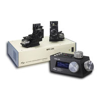
Sutter Instrument MPC-325-3 Operation Manual (71 pages)
Multi Motorized-Micromanipulator Control System
Brand:
Sutter Instrument
| Category:
Control Systems
| Size: 2 MB
Table of Contents
Disclaimer
5
Safety Warnings and Precautions
5
Electrical
5
Avoiding Electrical Shock and Fire-Related Injury
5
Electromagnetic Interference
5
Operational
6
Other
7
Handling Micropipettes
7
Table of Contents
9
1 Introduction
13
Structure of the MPC-325 Documentation Package
13
Components of the MPC-325 Series
13
2 Mpc-200 Multi-Manipulator Controller and Roe-200 Input Device Operations
15
Electrical Connections and Initial Operating Instructions
15
Initial Operating Instructions
15
Figure 2-1. Rear of MPC-200 Controller Cabinet
15
Main Controls on the ROE-200
17
White Buttons
17
Figure 2-2. Top View of ROE-200
17
Black Selector Switches
18
Other Controls on the ROE-200
19
Figure 2-3. Side View of ROE-200
19
Controls on the MPC-200
20
Figure 2-4. Configuration Switches on Rear of MPC-200 Controller Cabinet
21
Table 2-1. Configuration Switch Settings for Different Angles of Steepness
22
Figure 2-5. Configuration Switches (Rear of MPC-200 Controller)
23
3 Mp-225/M Manipulator Mechanical Mounting Instructions
25
Mounting MP-225/M to a Stand or Platform
25
Figure 3-1. Angled Side View of MP-225/M Showing Swing Gate and Mounting Adapter Plate
25
Setting Headstage/Pipette Angle and Pipette Exchange
26
Figure 3-2. Locations of Screws Used to Open Swing Gate and Changing Pipette Angle
26
Headstage Mounting
27
Figure 3-3. Headstage Mounting
27
Figure 3-4. Using a Dovetail for Headstage Mounting
27
Modular Construction
28
Minimizing Electrical Noise
28
Instructions for Changing Handedness
28
Instructions Used in Special Installations Only
29
Figure 3-5. Rotating the MP-225/M for Right and Left Handedness
29
4 Operations
31
First Time Use
31
Line Power (Mains)
31
Make It Go
31
Figure 4-1. MPC-200 Controller Cabinet (Rear View) Showing Power Connection and Fuse
31
Figure 4-2. Power Switch (Front Panel)
31
Basic Operation
32
Initialization
32
Standard Screen
32
No Manipulator Connected Screen
32
Diagonal-Mode Screen (DIAGONAL)
32
Move in Progress Screen
33
Setting Work Position (WORK POS)
33
5 External Control
35
General
35
Virtual COM Port (VCP) Serial Port Settings
35
Protocol and Handshaking
35
Table 6-1. USB-VCP Interface Serial Port Settings
35
Command Sequence Formatting
36
Axis Position Command Parameters
36
Microsteps and Microns (Micrometers)
37
Travel Ranges & Bounds
37
Travel Speed
37
Table 5-2. Microns/Microsteps Conversion Factors (Multipliers)
37
Table 6-3. Travel Distances and Bounds
37
Commands
38
Get Connected-Devices Status ('A') Command (FW <V3)
38
Get Connected-Devices Status ('U') Command (FW V3+)
38
Table 6-4. Travel Speeds
38
Table 5-5. Get Connected Devices Status ('A' Command (FW <3)
38
Get Active Device & Firmware Version ('K') Command
39
Table 5-6. Get Connected Devices Status ('A' (FW <3) or 'U' (FW 3+)) Command
39
Table 5-7. Get Active Device & Firmware Version ('K') Command
39
Get Current Position ('C') Command
40
Change Active Device ('I') Command
40
Table 5-8. Get Current Position ('C') Command
40
Move to Controller-Defined HOME Position ('H') Command
41
Move to Controller-Defined WORK Position ('Y') Command
41
Table 5-9. Change Active Device ('I') Command
41
Table 5-10. Move to Controller-Defined HOME Position ('H') Command
41
Table 5-11. Move to Controller -Defined WORK Position ('Y') Command
41
Move to Center Position ('N') Command (FW =< 1.03)
42
Calibrate ('N') Command (FW > 1.03)
42
Move to Specified Position Orthogonally at Full Speed ('M') Command
42
Table 5-12. Move to Center Position ('N') Command (FW <= 1.03)
42
Table 5-13. Calibrate ('N') Command (FW > 1.03)
42
Move to Specified Position in a Straight Line at Specified Speed ('S') Command
43
Table 5-14. Move to Specified Position ('M') Command
43
Table 6-15. Move to Specified Position in a Straight Line at Specified Speed ('S') Command
43
Interrupt Move ('^C') Command
44
Turn off S-Move Command Streaming Data ('F') Command
44
Table 6-16. Straight-Line Move 'S' Command Speeds
44
Table 5-16. Interrupt Move in Progress ('^C') Command
44
Turn on S-Move Command Streaming Data ('O') Command
45
Set ROE MODE ('L') Command
45
Command Notes
45
Table 6-18 Command to Disable Current-Position Streaming Data During an 'S'-Command-Initiated Move
45
Table 6-19 Command to Disable Current-Position Streaming Data During an 'S'-Command-Initiated Move
45
Table 5-17 Set ROE MODE ('L') Command
45
6 Maintenance
51
Appendix A. Limited Warranty
53
Appendix B. Accessories
55
Appendix C. Fuse Replacement
57
Figure C-1. Rear View of the MPC-200 Controller Cabinet Showing the Power Entry Module and Fuse Location
57
Appendix D. Technical Specifications
59
MPC-200 Controller
59
Roe-200
60
Appendix E. Quick Reference
61
External Control
61
Index
69
Advertisement
Advertisement
Related Products
Sutter Instrument MPC-325 Series
Sutter Instrument MPC-200
Sutter Instrument MPC-325-2
Sutter Instrument MPC-325-4
Sutter Instrument MPC-365 Series
Sutter Instrument MPC-385 Series
Sutter Instrument MPC-78
Sutter Instrument TRIO MPC-145 Series
Sutter Instrument TRIO MPC-145-2
Sutter Instrument TRIO MPC-145S
Sutter Instrument Categories
Laboratory Equipment
Amplifier
Control Systems
Controller
Work Light
More Sutter Instrument Manuals
Login
Sign In
OR
Sign in with Facebook
Sign in with Google
Upload manual
Upload from disk
Upload from URL